Application of gapped (EGLAs) or non-gapped (NGLAs) transmission line surge arresters (TLSAs) offers perhaps the best opportunity for power engineers to improve system reliability. However, as important as this may be, the value of using them transcends this one objective alone. There are also many additional benefits.
This edited contribution to INMR by arrester specialist, Jonathan Woodworth, reviewed a range of situations where TLSAs contribute to improving power systems.
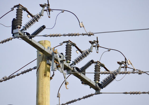
An NGLA is an arrester applied in parallel with transmission line insulators to prevent insulator flashover. An EGLA operates essentially the same way (see INMR Q2, 2015). If the phase to which these TLSAs are attached is struck by lightning or experiences a switching surge, the excess current and charge is conducted to ground. If the TLSA is applied to a shielded line, it quite often conducts current from the down ground onto the phase to avoid a back-flashover. While it is easy to visualize when a forward flash occurs, this is not so easy in the case of back-flashover.
line arrester (NGLA).
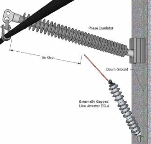
line arrester (EGLA).
Before going into various additional applications for TLSAs, it is important to deal with concerns some engineers express when using them for the first time – namely about long-term reliability and potential additional maintenance.
Indeed, there was a time when gapped silicon carbide arresters had questionable reliability. In the present MOV arrester era, however, reputable suppliers consistently achieve low failure rates that are close to those of insulators. In the case of manufacturers in the U.S., for example, recent experience with failure rates are in the 200 parts per million (ppm) range. This rate is most likely similar for reputable suppliers worldwide. Given this, there should be no hesitation on the part of new users toward line arresters based solely on reliability concerns.
In regard to possible additional maintenance needs, there are in fact typically none. If however users do wish to monitor their population of TLSAs, thermal imaging is the recommended route. At the same time, more versatile continuous condition monitoring of arresters is expected to soon become available.
Lowering Clearances on Systems > 345 kV
The National Electrical Safety Code (NESC, IEEE C2-2012) specifies horizontal and vertical clearances of unguarded parts and clearance to live parts of extra high voltage power systems of 345 kV and above. Basic clearances are specified, which can then be adjusted based on switching surge amplitudes. If line clearances are found inadequate to meet NESC criteria, TLSAs can economically control switching surge amplitudes with only a few installations along the line. For example, on a 500 kV system, maximum crest operating voltage (line-to-neutral) is 449 kV. If the switching surge (line-to-ground) voltage is 808 kV, switching surge factor is 808/449.1=1.8 pu.
In Table 124.1 Part B of the latest NESC (IEEE C2-2012), clearances are given for switching surge factors ranging from 1.8 to 2.7 pu for a 500 kV power system. The clearance for a 1.8 pu switching surge maximum is much less than for a 2.7 pu surge. This can make a significant difference in required width of a rightof- way, saving huge costs for a project. (An example was discussed in a paper presented by James Hunt of Salt River Project at the 2013 INMR WORLD CONGRESS in Vancouver).
Table 1 illustrates how much impact arresters can have on clearance requirements. If a 345 kV system, for example, is insulated with high creepage for contamination or other reasons, clearances can be reduced by as much as 57% using arresters. EGLA designs in such a case would need to be designed for switching and not only lightning surges. Note that other constraints on line clearances could also affect the minimum level attainable. ARC Flash requirements are known to be more stringent than standard clearances at certain voltages, while comfort level of workers under less clearance is another factor. Mechanical considerations, such as ice, wind and sag, also need to be considered when reducing clearances.
Substation & Transmission Line Voltage Uprating
Voltage uprating involves increasing the operating voltage while maintaining the original insulation level. Conversion of existing transmission lines and substations to higher voltages becomes much more practical with application of line arresters. For example, uprating 69 to 230 kV lines using such arresters has already been implemented with success.
Existing substations can be uprated to a higher voltage by replacing circuit breakers, transformers and other voltage-sensitive equipment without having to completely rebuild the facility. By installing line arresters in specific locations, such as line entrances, clearances at the lower voltage level will be acceptable at the uprated voltage. Voltage uprating has been accomplished on the following systems, according to IEEE Standard 1427:
• 115 kV, 550 kV BIL class substations converted to 230 kV;
• 69 kV, 350 kV BIL class substations converted to 138 kV;
• 69 kV, 350 kV BIL class substations converted to 115 kV.
Financial benefits with uprating are significant because associated costs are far less than rebuilding the entire substation. With line arresters and voltage uprating, substations can also use compact bus spacing, thereby offering economic benefits where land costs are high. Moreover, where the land necessary to build a substation with conventional clearances is not available, the compact bus substation is a viable alternative. Community acceptance of a substation can also be enhanced using a compact bus design that occupies a smaller footprint than an equivalent conventional substation.
Less clearance when uprating a system can also lead to lower bus heights, which can lead to lower costs for aesthetic treatments such as walls and other barriers, if required. Additions to existing substations are in some cases difficult to make due to lack of space for installing new equipment. Employing lower clearances through use of line arresters at a substation makes it possible to add new equipment with the assurance that proper electrical clearances are maintained. (See IEEE 1427 for more information).
Temporarily Reduce Minimum Approach Distance (MAD)
At times, maintenance needs to be completed with a system energized and workers must be aware of the minimum approach distance (MAD) to the line. MAD is defined as the closest a worker or conductive tool held by a worker is permitted to approach an exposed energized conductor. Since MAD is determined by maximum switching surge level of lines above 345 kV and lightning surges on lines below 345 kV, this level can be affected by temporary installation of arresters.
While this is still at the experimental stage at most utilities, it seems likely that arresters will be utilized more and more to temporarily change the MAD. A line arrester, due to its minimal weight, is a perfect candidate for this application and, here, an EGLA type may be more suited for the application since lightning and switching residual voltage can be as much as 25% lower. In both cases, however, the MAD can be reduced to a level that can even allow access to towers without an outage where otherwise one would be required. At the October IEEE Surge Protective Devices Meeting, for example, a task force was created to develop guidelines for using arresters to reduce MAD for workers. A recommendation is due next year.
Lower Lightning-Induced Momentary Outages
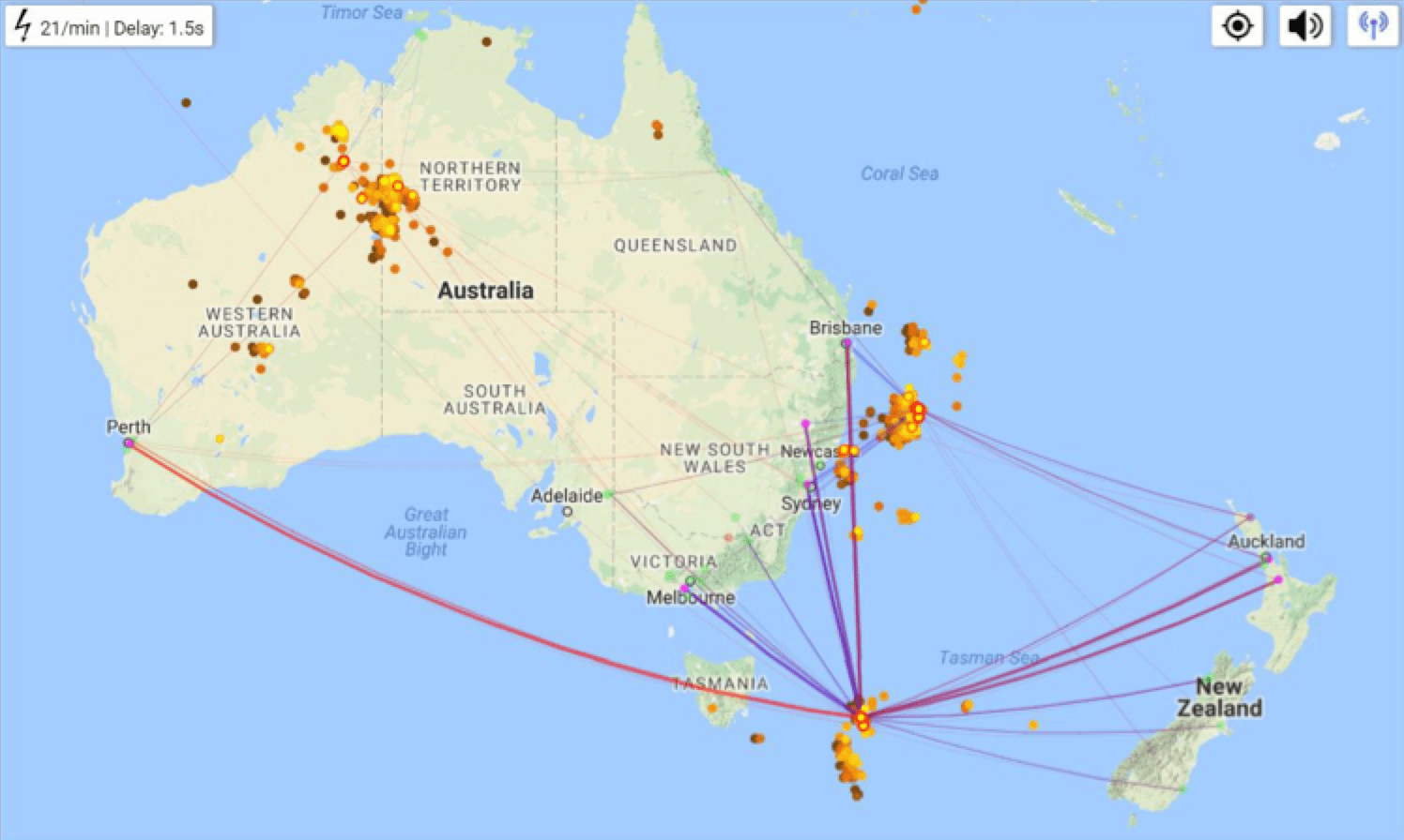
A transmission line might not need TLSA protection, especially if it has a lightning induced outage rate of zero. However, in other cases application of TLSAs can make a big difference in transmission line outage rates caused by back-flash. A map of the type shown in Fig. 3 offers a resource for engineers to become more acquainted with lightning hit rates in their areas of interest.
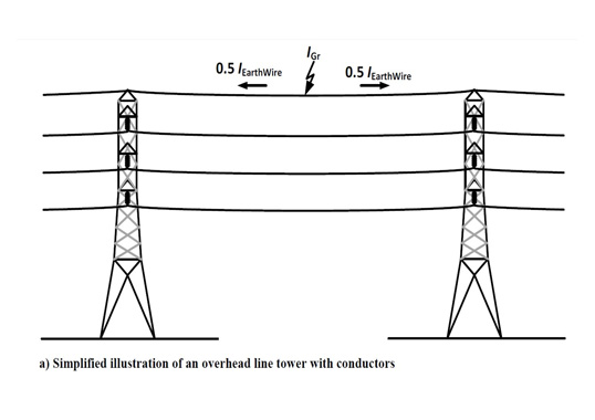
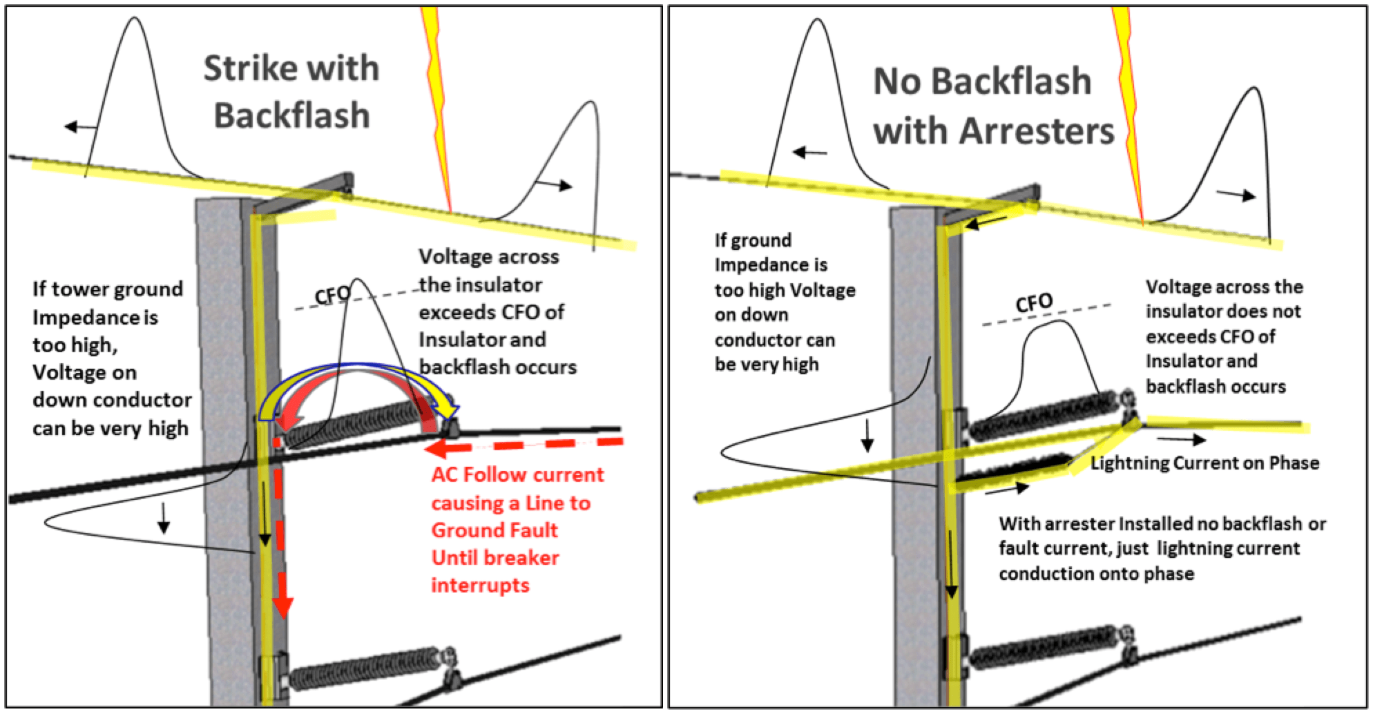
If a transmission line has a high rate of outages due to lightning, this is most likely due to back-flash and the most common cause is when there is a lightning strike to the overhead shield wire and tower ground impedance is too high. The reason for the term ‘backflashover’ is that it is in the opposite direction of flashovers produced during a direct strike to a phase. Back-flashover is usually followed by a standard forward flashover of the insulator, providing a path for power frequency current (fault) that requires breaker operation to terminate. Fig. 4 shows an overview of the back-flash process.
There are basically two ways to reduce back-flash rate of a transmission line: the first and more often used method is to improve tower ground resistance and, up until 20 years ago, this was the only option. Since then, however, installation of surge arresters has become another means to improve lightning performance.
There are several methods employed to mitigate lightning on shielded lines using arresters. The first is to run a study of the system and determine whether addition of a few arresters significantly reduces outage rate. This method uses fewer arresters and costs less than a full protection scheme. The second and less used method is to install surge arresters on every phase of every tower, which will essentially make the system ‘lightning proof’. A third method, referred to as sectionalized arrester protection, is when arresters are used to protect certain areas prone to outages due to lightning. Here, high outage rates can be reduced essentially to zero by installing arresters only in affected areas, which typically include mountaintops, dry planes and rocky soil.
Compact Lines
A compact transmission line is one that looks like common, acceptable distribution lines running through urban areas and usually features the following:
• Single-pole structures;
• Relatively short spans (30-150 m);
• Armless or single-arm construction;
• Reduced separation between phases;
• Suitable for narrow right-of-way or roadside installation.
According to W. A. Chisholm, et al., “These features make the compact line designs suitable for use in congested urban areas. There are other benefits compared to multiple distribution lines that could provide similar power transfer. Rebuilding an existing circuit at a higher voltage level on the same rightof- way may be the only feasible way to increase capacity. Compact designs may have lower capital and maintenance costs, lower line losses and may achieve important reductions in electric and magnetic fields. Compact design also tends to simplify some mechanical issues. When armless or single-arm construction with post insulators is selected, conductors are fixed at each pole. This simplifies tension stringing, thermal rating, wind loading and other design and construction issues. The short spans of a compact design reduce the magnitude of high-temperature sag, galloping and large-amplitude conductor motion. In many cases, line tension can be reduced, relaxing pole strength requirements and concerns about aeolian vibration damage.” A good example of such a line (shown in Fig. 5) is a 69 kV compact line used in Florida for over 20 years. The main reason for this particular design was to reduce visual impact and make the transmission line appear more like a distribution system.
Open Breaker Protection
Station class arresters are universally applied to transformers at substations however protection of open breakers is generally applied less than half the time. Here, application of arresters at the substation’s line entrance protects the bushings of open breakers.
During normal operation, the substation breaker is closed and both bushings are partially protected by the arresters installed at the transformer. But during a multi-strike event during which the breaker opens to clear a fault, the second or third stroke of the flash can enter the station while the beaker is still open to clear the fault. This second stroke can flashover the line side bushing of the breaker with high risk of long-term damage. Of course, this is a low probability scenario but, to assess real level of risk, a study should be conducted for the specific substation and surrounding lines.
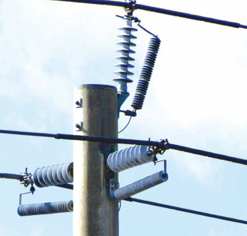
Line arresters are not generally used for this application but certainly can help overcome any such risk. Fig. 6, for example, shows a space-saving installation of line entrance arresters. Here, it is important that ground resistance of the pole where they are installed should be the same as at the substation. If the first tower out from the station is used instead, it should not be located too far away or it will not effectively protect an open breaker.
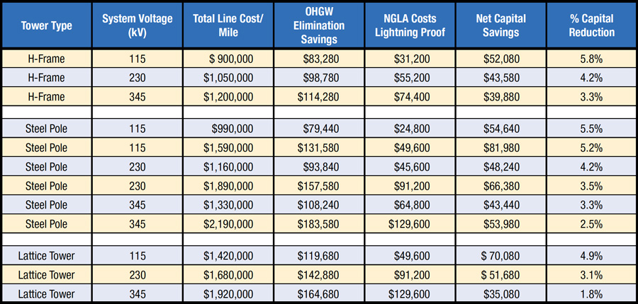
Lowering Cost of New Line Construction
A potentially significant benefit of using line arresters instead of an overhead ground wire is construction cost savings. For example, a 2014 research project on behalf of the New York State Energy Research and Development Authority (NYSERDA), evaluated the cost savings for several different systems. As shown in Table 2, in every case, transmission lines with arresters in the place of OHGW cost less initially and also going forward. The report found that construction savings were between 1.8% and 5.8% of the total cost of the line for various line-type studies. Moreover, installation of arresters on all phases of every tower make a line lightning proof. If only the top phase is equipped with arresters, then the top phase serves as the OHGW and cost savings can be even greater.
Extending Life of Breakers at Substations
Application of TLSAs along a transmission line reduces stress on breakers at substations and extends their service life. Even those transmission lines protected from lightning by shield wires still experience single line-to-ground faults when there is back-flashover of an insulator due to high ground resistance or an extra high current lightning stroke. When this happens, a breaker between the fault and power source will need to operate to interrupt current flow. However, should a line be equipped with TLSAs, such breaker operation would not be necessary. Breakers have a finite number of operations before maintenance is required and therefore any reduction in this number will extend their service life.
Reducing Cost of Emergency Standby Capacity
Some utilities must deal with significant risk of lightning outages during summer. For example, if a power source is far from the major demand center and transmission lines pass through high-lightning areas, risk of momentary outages can be high. One way to mitigate this risk is to run local generators and depend less on the lower-cost but distant source.
If arresters are used on the transmission line in addition to existing OHGW, the probability of any lightning induced outage is reduced to zero. Cost to install several hundred kilometers of arrester protection is likely much less than to run higher-cost local generation. This application of line arresters can generate great savings – both for customers and the affected power utility.
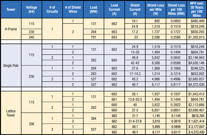
Lowering System Losses
This application applies mainly for new construction but could also work for older lines should the OHGW reach end-of-life. It is well known that OHGW can generate losses on a system if they are grounded at tower tops. Such losses are inductive in nature from load flowing in phase conductors and become higher the closer the OHGW is to the phase conductors. Losses depend on type of line, number of shield wires and current load on the system. As seen from Table 3 for the case of a single pole, two-circuit 115 kV line, lifetime savings for heavily loaded lines can amount to as much as US$ 4.6 million per 100 miles (160 km) of line.
Conclusions
Application of either NGLAs or EGLAs can improve the design and operation of power systems. These TLSAs not only render any line lightning proof but also lower construction costs, increase system reliability, and reduce the required width of a right-of-way. Engineers responsible for system reliability or planning should clearly consider the possibilities and benefits offered by this type of surge arrester.
[inline_ad_block]