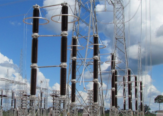
Two types of fault currents can appear on power systems: ground and phase-to-phase. More important with regard to arresters is the former, which is basically the current that flows through the circuit when there is a short to ground. Maximum available fault current during such an event will vary along the length of the circuit, with more current available when the short occurs closer to the source. As far as arresters are concerned, the fault current of real consequence is that which flows through a shorted or failed arrester. Ground fault current that flows past the terminals of a functioning arrester to a short somewhere down the line will have no effect on that arrester.
When ground fault current is triggered by a failing or failed arrester, available fault current will flow initially through and around its internal components. But if that current flow is not diverted to the outside in less than a full cycle, probability of an explosive event increases significantly. Rapidly providing an external path for the fault current around the arrester is the basic scheme used by manufacturers to achieve good short circuit withstand capability. Rapid arc transfer for those arrester designs that contain substantial internal air volume, such as porcelain-housed or polymeric tube type, is achieved using well-developed vents on the ends of the unit. Under a perfect arc transfer scenario, these vents open rapidly and expel the evolving hot ionized gas, forming a lower impedance path. For solid core arrester designs, such as the wrap type, gases generated from the event burst through the sides of the polymeric housing and form an external pathway. Both systems have been in use for many years.
In North America, for example, 65 kA of available fault current at a substation is presently not uncommon. However 80 kA is now becoming more common and 90 kA is ‘around the corner’. Not all arresters suppliers can offer 80 kA withstand capability and, only a few years ago, none offered 90 kA. For an arrester design to be certified at such higher short circuit withstand capabilities, it must pass a series of short circuit tests, as specified in IEC 60099-4 as well as IEEE C62.11. (Fortunately, these test specifications are identical through co-operation between the working groups that created them and which were unified between 2006 and 2009).
CLICK TO ENLARGE
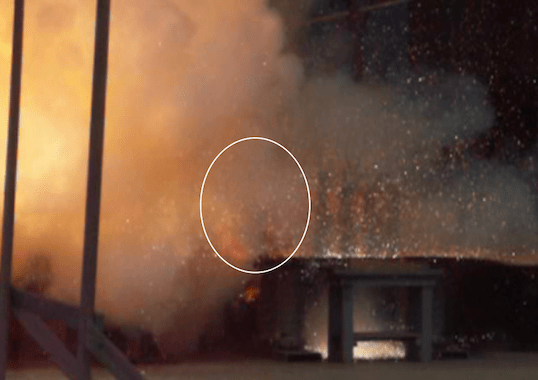
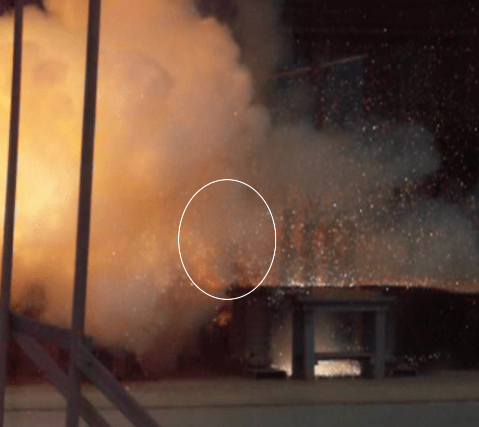
The short circuit test series is the most onerous of all tests to be performed. Basically, each arrester design must be tested at two or three current levels and the fault current must flow through the arrester from 0.2 to several seconds. At the end, no parts are permitted to fall outside a circle whose radius is the height of the arrester. Moreover, no fire can be sustained for more than a few minutes. Three aspects of this test make it challenging: first, the test currents are either hard to attain or hard to maintain; secondly, set-up is laborious; and thirdly, simulating an overloaded arrester is as much ‘art’ as science. Only the largest high power laboratories are able to perform this test and, when the test is applied to higher voltage rated samples, that number becomes more limited still.
When the short circuit tests were unified, there were two major improvements. One was that a third current level was added in the case of the test for porcelain-housed arresters. It was hoped that testing at this intermediate current level would reduce the number of reported violent failures of certified porcelain-housed arrester designs. The other improvement was that the first half-cycle fault-current asymmetry was no longer required in the case of polymeric housings with no appreciable internal gas volume. This improvement was predicated on results of tests reported in 2004 by then INMR columnist Dr. René Smeets of KEMA Laboratories. It was found at that time that the rate of energy input into the arc, still internal to the arrester just after short-circuit initiation, was much faster with symmetrical current than with asymmetric current. Testing with symmetrical current and higher rate of energy input was therefore felt to impose more severe duty on polymeric arresters with the solid core design than using asymmetric current. Fortunately, this test is easier to run than the standard asymmetric test still required for porcelain arresters.
Because fault current tests can only be run at voltages well below the rating of most arresters, special failure schemes had to be devised. The arrester failure sequence and the short circuit event are completed one after the other, sometimes in separate laboratories. While there are upper and lower limits on test parameters, these are quite broad and the final pass/fail results of the test can be modified significantly if the transition from one sequence to the other is not performed consistently or correctly. When these parameters are more constrained and the sequence more standardized, the result will be more consistent testing from laboratory to laboratory and from one design to another.
Jonathan Woodworth
Co-Convenor of IEC TC37 MT4 responsible for IEC 60099-4
[inline_ad_block]