Demand for testing at HVDC and UHV DC levels has been rising rapidly in recent years, with typical test objects that include valves, cables, line and station post insulators, cable accessories, wall and transformer bushings and optical instrument transformers. While some tests are purely dielectric, in many cases they also include pollution testing, which in DC is the main dimensioning factor for outdoor insulation. For porcelain and glass insulators, pollution test methods for HVDC applications are set out in the most recent version of IEC 61245. Similarly, CIGRE Guidelines for selecting and dimensioning polymeric insulators for pollution testing under DC have been published in Technical Brochure 518. Still, compared to AC, there have been relatively limited standards available for users to test polymeric insulators under DC.
Given this, customer specifications sometimes still refer to past standards that no longer adequately reflect current knowledge. In fact, lack of standardized DC test methods has forced some utilities to specify tests on items such as composite post insulators that are not relevant for the application since they are not representative of actual service conditions. Similarly, testing on cable systems has been performed in accordance with CIGRE TB 496 “Recommendations for testing DC extruded Cable Systems for power transmission at a rated voltage up to 500 kV”. Here too, there has been a comparative lack of standards. Dan Windmar and Göran Olsson of STRI in Sweden highlight the issues that must be considered whenever performing dielectric, pollution and other climatic testing on different high voltage equipment with particular emphasis on DC.
DC Testing of Equipment
Insulators
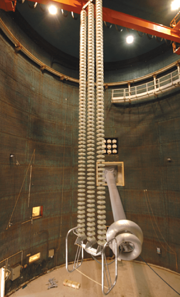
STRI has invested in unique facilities allowing full-scale dielectric and pollution testing of ±800 kV DC ceramic, glass and composite line insulators. The DC generator can supply up to 1250 kV for indoor laboratory testing and 1050 kV for the outdoor test station. The climate test hall for these tests has a diameter of 18 m and height of 25 m and temperature can be controlled from -12°C to +55°C. As such, dielectric and pollution as well as ice and snow tests can all be performed.
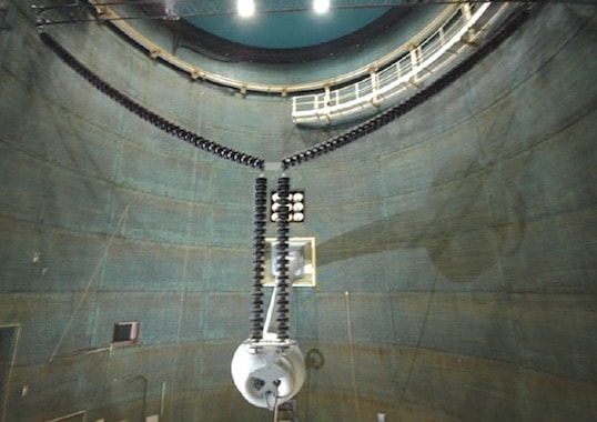
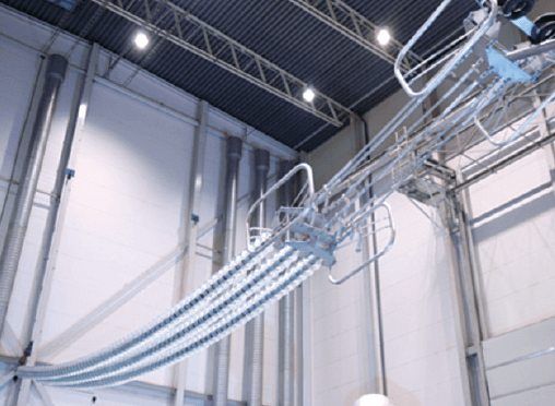
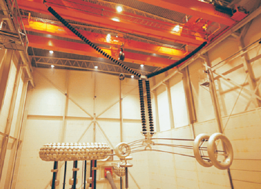
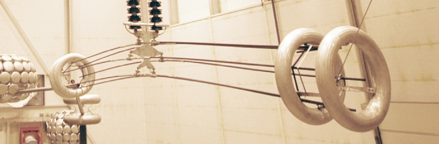
Dielectric testing of tension strings is done in a horizontal or working position in the high voltage hall (see Fig. 1) and this places demanding requirements on the building since it must support a high load at the centre of the structure. This challenge has been solved by releasing some of the load through an external wire attached to the ground. An alternative to test tension strings would be in the vertical position, as during pollution testing. While this would simplify test set-up, it would place greater demands on the insulation, particularly during rain tests, since the rain would accumulate at the bottom of the tension string. Dielectric testing of Y, I and V-string configurations is carried out by hanging the insulator string from the crane in the HV hall with a lattice structure, thus simulating the closest parts of the transmission tower (as in Fig. 2).
A number of DC dielectric tests have been performed for manufacturers of composite, porcelain and glass insulators. Typical tests include DC dry and wet withstand test, RIV and dry and wet switching impulse, where ‘wet’ means a rain test. It has been clear from such testing that the standards are not up-to-date, especially when it comes to wet withstand testing at UHV DC levels.
CLICK TO ENLARGE
CLICK TO ENLARGE
CLICK TO ENLARGE
CLICK TO ENLARGE
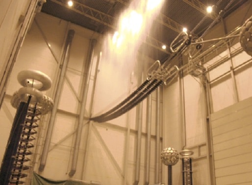
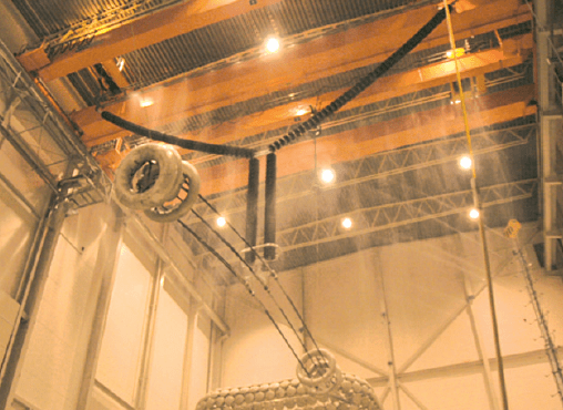
There are two main issues with wet testing: first, in order to create uniform rain on tension insulators, nozzles are installed on the roof of the high voltage hall (see Fig. 3). The standard requires rain to be calibrated without applied voltage but applying DC voltage at the live end of the string will charge water droplets. These will therefore be repelled from the electrodes. Thus, uniform water distribution calibrated without voltage is no longer uniform and this needs to be taken into account when updating relevant standards. Second, when testing suspension strings, rain is to be applied by a specially designed rain ramp. This needs to be installed quite high to have the rain uniformly distributed along the insulator while at the same time a safe distance from the insulator string to avoid flashover to the ramp. This puts special demands on the nozzles since they need to deliver the rain a long distance – typically from 10 to 11 m. In addition, STRI employs another rain system from the roof, in particular for testing Y and V-strings (see Fig. 4). This is necessary to fulfil requirements on both the horizontal and vertical components of the rain. Another factor adding complexity to fulfilling requirements on the vertical and horizontal components is that all the rain from insulators located above collects at the bottom of the Y-string. This practical experience needs to be considered in revision of the standards. Rain testing of large structures such as full-scale DC insulator strings has to be done in an indoor environment to assure correct distribution of the rain’s vertical and horizontal components.
Pollution Testing
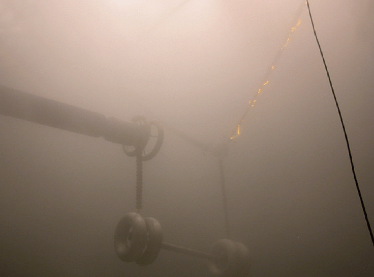
Using the climate hall described above, full-scale solid layer pollution tests were performed on three possible line insulation options for ±800 kV lines in China and India. These options included glass and porcelain cap & pin insulators as well as silicone composite insulators. One practical complication was verifying uniformity of distribution of steam fog during these full-scale tests. An example of pollution testing on a glass tension string is shown in Fig. 5. The tension string was tested vertically in contrast to its natural horizontal position because it is not feasible to test 13 m long 800 kV DC tension strings in horizontal position while maintaining a safe distance to the grounded side. This would have required the climate chamber to be the size of a high voltage laboratory. But testing in a vertical position is more demanding on withstand of the insulator string since condensation of fog on the insulator surface will create runnels (i.e. small water channels) along the insulator string. Another example of complexity in such testing is need for careful calibration of fog uniformity. In this case, it was achieved by installing two small, energized insulators at the level of the top and bottom electrodes of the 800 kV insulators. Results of monitoring leakage current on them for 100 minutes confirmed uniform such distribution.
CLICK TO ENLARGE

CLICK TO ENLARGE
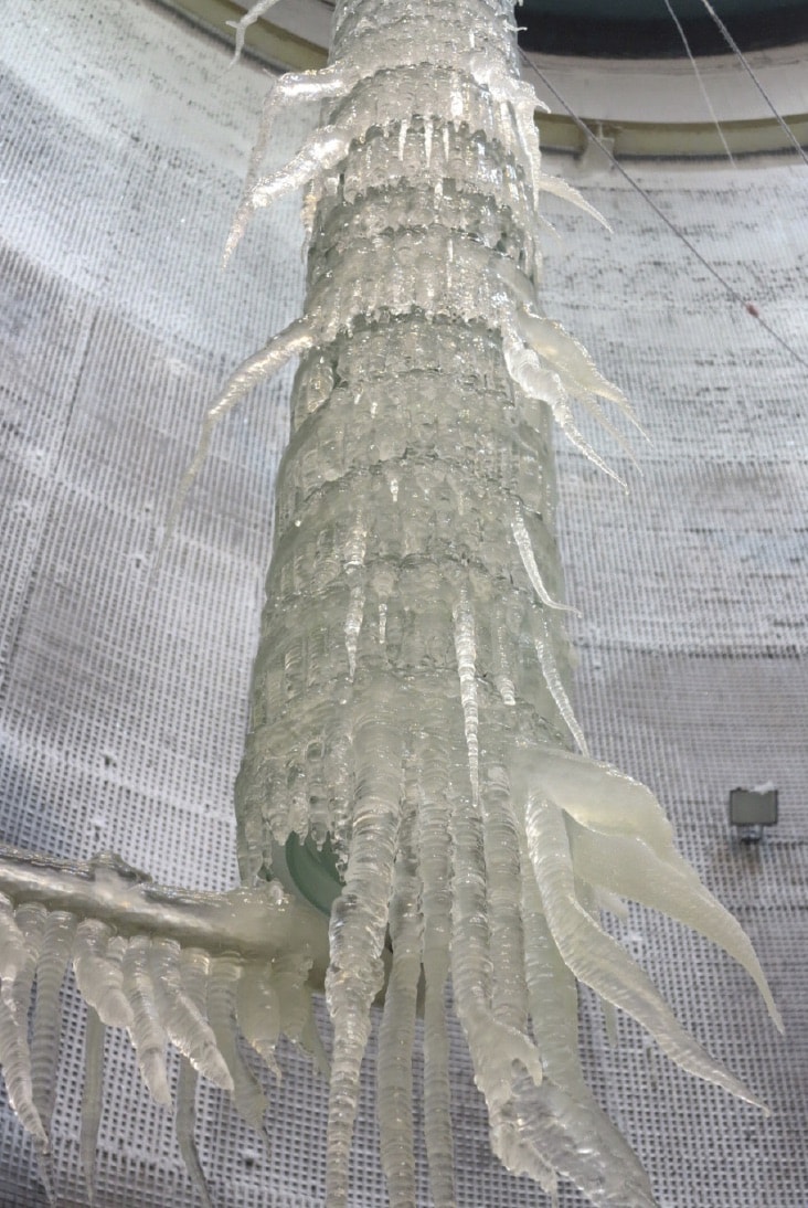
The climate chamber allows simulating ice and snow conditions and also makes it possible to have a combination of pollution and ice tests, e.g. when insulators are first contaminated and then accreted by ice made from water having a certain conductivity. For DC, this has so far been achieved only for full-scale ±350 kV tests, however a feasibility study confirmed that it is also possible for ±800 kV. The unique climate chamber also provides the possibility to produce different types of ice (e.g. glaze, rime) and snow with different densities and conductivities according to customer requirements. Fig. 8 shows an example of glazed ice in combination with pollution accreted under -350 kV.
CLICK TO ENLARGE
CLICK TO ENLARGE
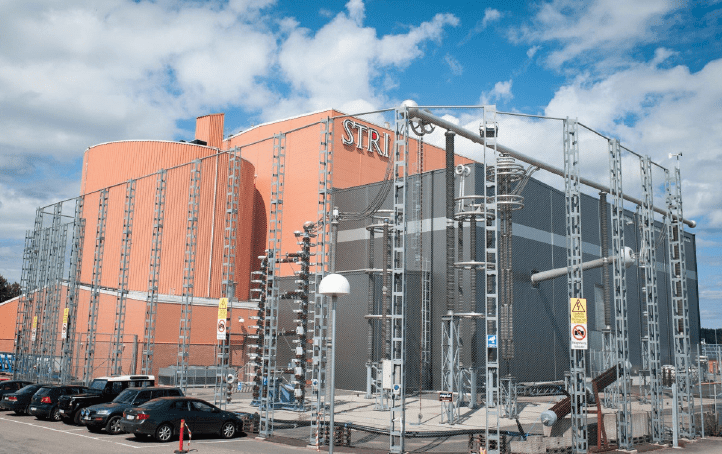
Another important issue for polymeric insulators is verifying long-term performance. In the case of STRI, this is done at an adjacent outdoor test facility where all types of station and apparatus insulation for ±800 kV projects have been tested. Equipment installed here includes a wall bushing, optical current transformer, voltage divider, pole arrester, smoothing reactor capacitor, RI capacitor, disconnector and by-pass breaker. All insulators and equipment have been tested fullscale at 850 kV, and also at elevated voltages, for over 2 years and then tested again for an additional 2 years. Several new insulator options for ±800 kV, including a hybrid insulator combining a porcelain cylinder and silicone rubber sheds, have also been verified at this test station.
Apparatus Insulators
There are similarities between apparatus insulators and line insulators when it comes to the challenges of dielectric and pollution testing. For example, in the case of rain testing, the same issues apply in regard to distance between nozzles and test object to ensure correct distribution of vertical as well as horizontal components of rain along an insulator that can be up to 11 m long. Also, due to lack of standards for pollution testing of composite apparatus insulators, utilities often apply the same requirements for composite insulators as for porcelain insulators. An example of this is the requirement for the pre-conditioning phase of the salt fog test, which is copied directly from the standard for porcelain and applied to composite insulators. This phase requires a number of forced flashovers and was historically implemented in the standards for porcelain to ensure that the surface is free from contaminants before the main test, i.e. initial surface conditions should not affect the test. However, for composite insulators such a phase can lead to reduction in hydrophobicity. The output could then be completely different, i.e. pre-conditioning has actually influenced results of the main test. Moreover, to obtain forced flashovers in some cases, the test objects have to be divided into smaller parts by short-circuiting and testing these sections one-by-one, which is time consuming.
CLICK TO ENLARGE
Insulator Accessories
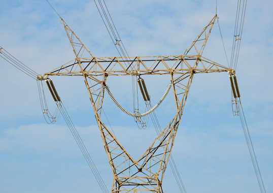
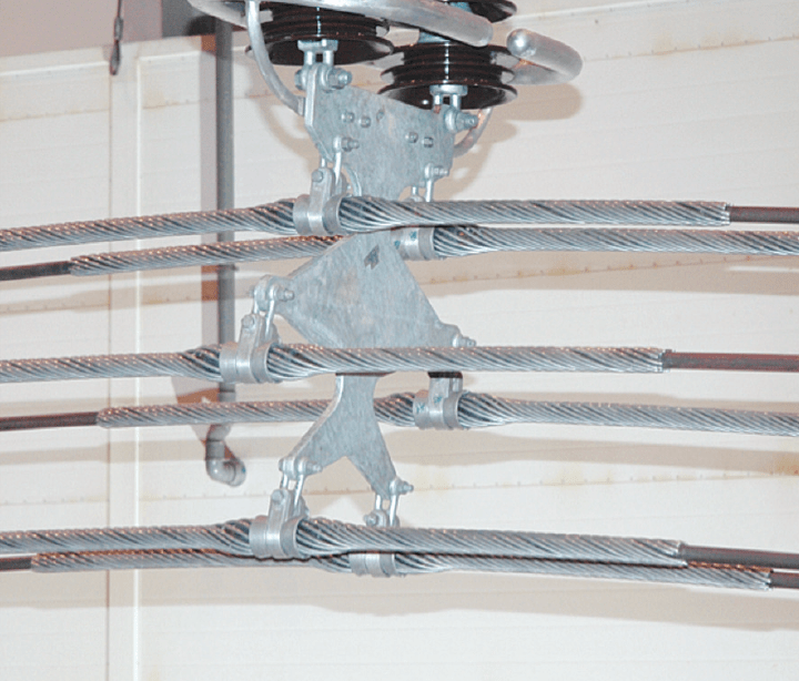
Metallic hardware is often tested at the same time as the insulator string. However, the main request from manufacturers of these accessories is often only to verify RIV and corona, in accordance with IEC 61284. Practically, this means that the test must be performed on a complete string with hardware attached (see Fig. 10). While the standard allows for some deviation, this has to be agreed upon between supplier and buyer. It would therefore seem worthwhile to revise the standard to allow mock-ups of the insulator string and also to perform the RIV/corona test in a vertical as well as horizontal position. With demand for increasing DC voltage and therefore number of sub-conductors in the bundle, this has direct influence on size of accessories. Increase in size is not a problem for service however creates problems during testing, the most important being that electric field on the surface of hardware becomes too high due to constraints in size of high voltage halls. Testing a 6-conductor bundle, for example, (as in Fig. 11) already provides a higher electric field on the surface compared to actual service conditions due to the walls and roof of the test hall. The standard allows two ways of testing: by voltage or by voltage gradient. Since the size limitations of a HV test hall create higher electric fields on the surface of accessories than encountered in service, the voltage gradient method would yield the more correct result. However, in this case there is need to specify voltage gradient, which is currently not given but could be added to future revisions of IEC 61284. Modern software for E-field calculation provide such verification, however has so far been verified only for AC. A similar comprehensive study for DC is recommended.
CLICK TO ENLARGE
Cable Systems
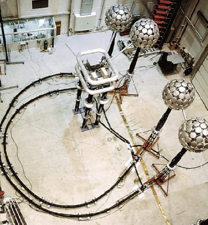
There are still no DC cables for UHV but XLPE cable is available for 525 kV DC. Testing cable systems intended for EHV DC applications is typically a challenge since several parameters can complicate interpretation of results. For this reason, it is important that testing be done in an accredited laboratory with experienced personnel and also HV equipment that has stable long-term performance. All measured parameters must be registered in a computer that allows post processing and inspection. HVDC cable systems are tested in similar ways to HVAC systems in regard to load cycling, except of course for polarity reversal. The major deviation comes during the final test where lightning and/or switching impulses should be applied superimposed on the DC voltage. The test circuit to achieve this must be carefully designed to avoid flashovers and also to protect the impulse generator for the DC voltage as well as the DC generator for the impulse voltage. Performing such a type test in a high voltage hall is difficult but manageable (see Fig. 12). However, after performing a 1-year pre-qualification test on a 100+ m cable, CIGRE guidelines allow for superimposed impulse testing on a 30 m section. Yet requirements from end users can be that the complete system, with all accessories, is to be tested. Applying superimposed impulses at DC voltage with a full-length cable system places extremely high requirements on the test circuit and also on the individual components, such as DC generator and impulse generator.
CLICK TO ENLARGE
CLICK TO ENLARGE
Conclusions
This report summarizes practical experience gathered from HVDC dielectric and pollution testing on different types of equipment. Based on this, there is still much work needed to adapt different standards to the level where testing can be performed in existing high voltage laboratories, even though system voltage levels are increasing.
[inline_ad_block]