This edited past contribution to INMR by Jesse Hoffman of Energy Systems Group in the United States, explained how design of large PV systems interconnected to medium voltage distribution lines can include a variety of strategies for placement of surge arresters. Proper evaluation of system and design decreases the quantity of distribution components, reduces required equipment insulation levels and lowers system costs.
Development of medium voltage distribution level interconnected photovoltaic (PV) generation systems has increased significantly and now is nearly as common as small-scale building level PV systems. These larger systems range in size from 2 MW to 30 MW and connect to utility distribution lines ranging from 12.47 kV to 34.5 kV in typical U.S. applications. While utility scale systems offer lower implementation costs per kW than small-scale PV systems, a significant capital investment is still required.
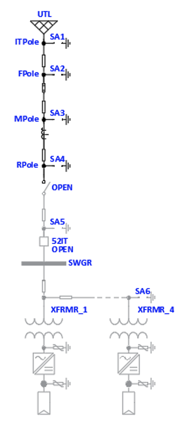
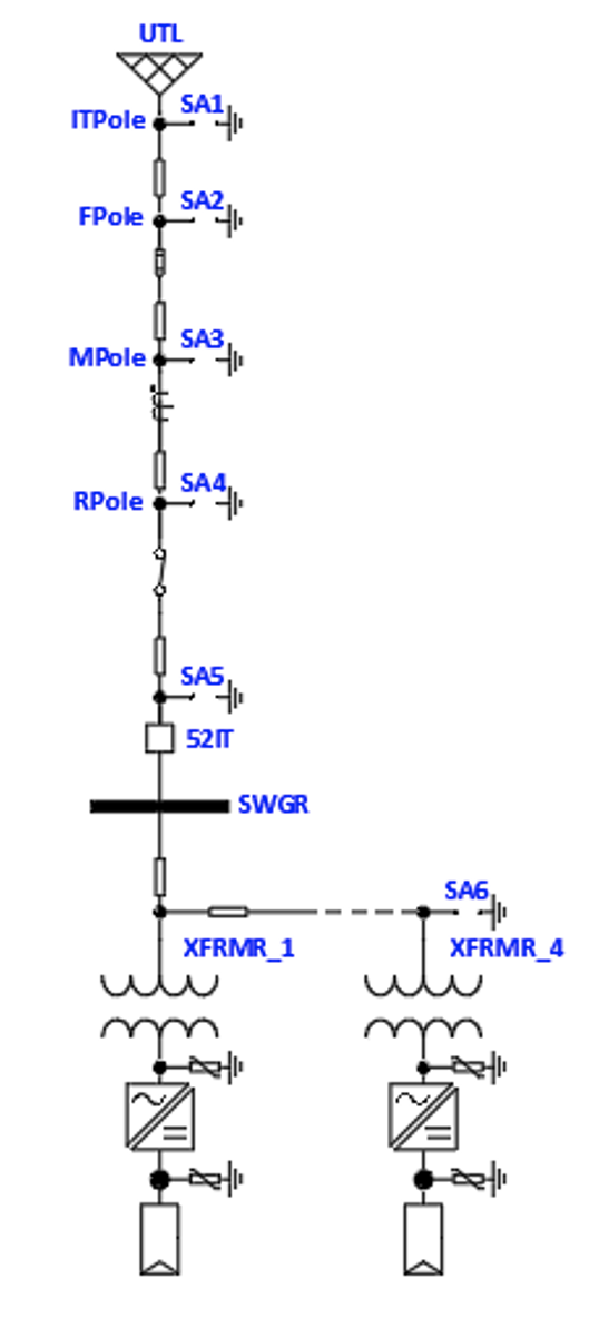
These systems typically include installation of new overhead distribution lines, disconnect switches as well as metering and protective devices. Common design practice sees these devices each mounted on their own pole prior to the underground service riser that connects to the PV system interconnecting switchgear. From the switchgear, a collector grid of underground cables is used to interconnect each PV step-up transformer. Each step-up transformer connects to one or more PV inverters, which convert DC PV power to AC power for injection into the utility grid. This typical design topology, shown in Fig. 1, includes several surge arresters within the power path (medium voltage, low voltage and DC).
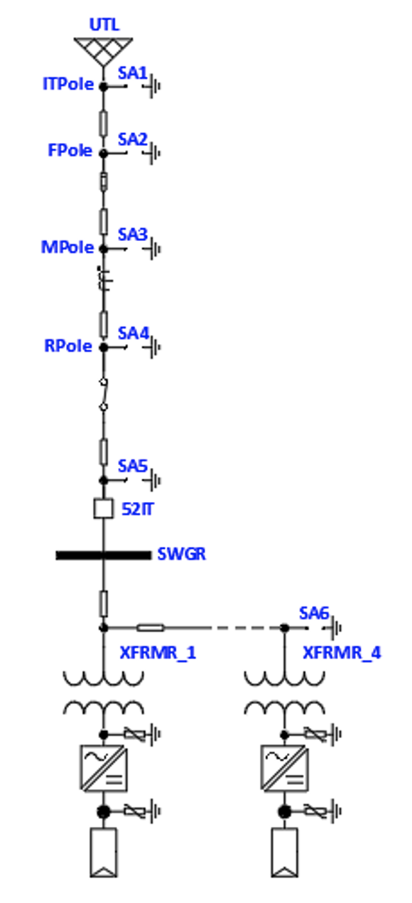
It is notable that on the overhead line sections, many surge arresters are used sequentially, one per power pole. The interconnecting switchgear includes surge arresters, and each collector grid cable has a single set of surge arresters on the last PV step-up transformer. All PV transformers between the interconnecting switchgear and the last transformer in the collector grid include no surge arresters since each transformer feed-through connection is occupied by an interconnecting cable. Using a case study of an actual system, the following sections review a typical design strategy by modeling the system in EMTP-RV and evaluating the protective ratios for alternate arrester placement, ratings and configurations.
System Parameters
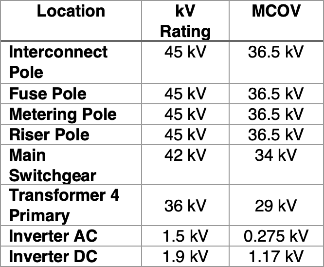
The 10 MW PV system is interconnected to an existing 34.5 kV overhead distribution line. As shown in Fig. 1, the interconnection includes several pole-mounted devices, each including a set of surge arresters. Two additional arrester sets are included, one at the switchgear and one on the last transformer. The following table summarizes the arrester ratings for the system.
The distribution system is solidly grounded, as per the utility standards, and is not designed for islanded microgrid operation. Each 2 MW PV inverter skid and step-up transformer is located remotely from the main switchgear, and power is supplied via a collector grid of 1/0 Copper 34.5 kV cable, with a total length of 1550 ft (472 m). Only Transformer 4 includes an elbow mounted lightning arrester. On the secondary side of the transformer, each inverter skid includes AC low voltage surge protection device (SPD) and at the inverter MPPT inputs DC SPDs. AC and DC SPDs were a selected option for purchase from the inverter manufacturer per standard practices. DC combiner boxes did not include DC SPDs.
In order to evaluate the effectiveness of the typical arrester design approach, a direct lightning stroke is modeled on the incoming overhead line at the interconnect pole. The surge current is 20 kA using the standard 8/20 µs wave shape in the following form:
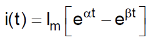
where; Im = 20kA, α = -72274/s and β = -98417/s. The surge is timed to start at the peak phase-a voltage.
Each equipment Basic Insulation Level (BIL) is indicated below, as are the required protective ratios (PR).
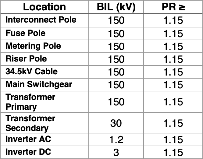
where the PR is calculated as:
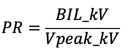
The equipment will be considered adequately protected if the PR ≥ 1.15.

Design Configuration
Considering that each utility pole includes its own arrester set, the analysis reviews the collective benefit of installing all four arresters, sequentially added, one-by-one, down to the final most distant transformer in the collector grid. The analysis first reviews the overhead line system, then includes the PV generation system using this sequential approach.
Pole Mounted Arresters
As shown in Fig. 2, each pole includes both pole-mounted equipment and identical arresters. Each pole is separated by 30 ft (circa 9 m) of overhead line and it is not possible to partially disconnect the overhead line segment or operate the system without the line sections with equipment in service.
This configuration is widely adopted in PV systems of this size range, however alternate configurations utilizing pad-mounted fault interrupters are used which combine the disconnect, metering and arresters in one package, or utilizing a single set of arresters only on the interconnecting pole. In this configuration, during periods of PV system maintenance or if the utility requires the system to be separated from the utility, the rise pole disconnect switch would be open.

To evaluate the relative effectiveness of the arrester system in this configuration, a direct lightning stroke on the incoming line at the interconnect pole is modeled with no arresters. The effect of the 20 kA stroke results in a 350 kV surge voltage at the main switchgear, which is significantly above the BIL rating of the 34.5 kV equipment and certainly justifies installation of arresters in the system.
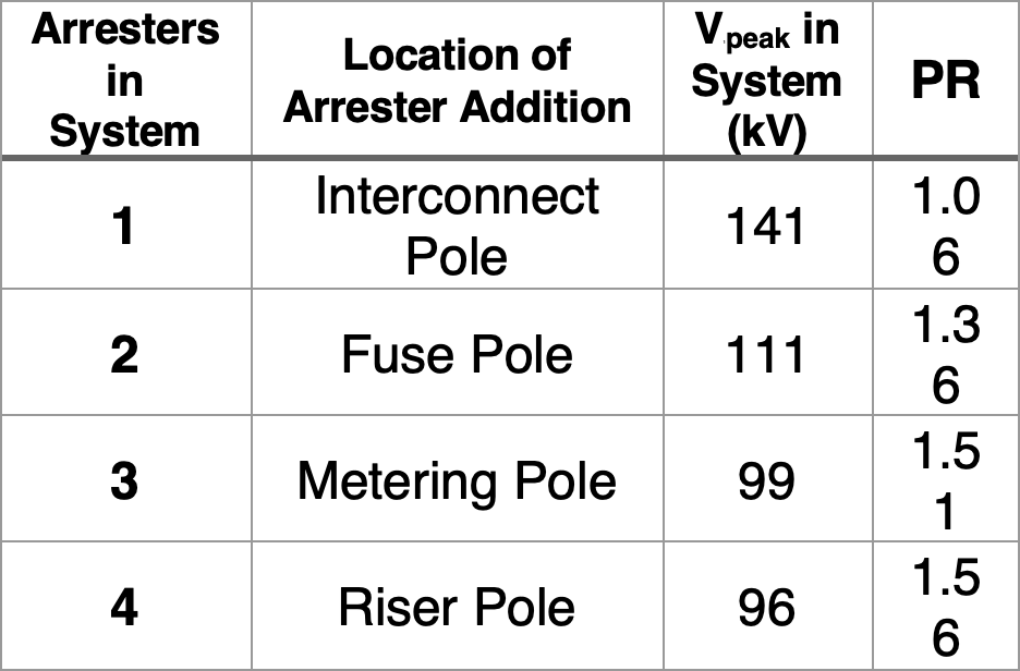
Considering the interconnect pole is nearest to the interconnecting overhead line system, the first analysis includes arresters at the interconnect pole, successive analysis runs, each adding an arrester on the next pole closer to the PV generation system, are presented. Initially, results are provided for the voltage surge assuming the PV generation system is disconnected. Vpeak is reported at the location within the system that experiences the highest surge voltage. In most cases, the protective ratio is adequate to provide protection for the distribution equipment. It should be noted that the lower ratings of arresters in this system could have been used, which would increase the protective ratios.
In this configuration, during periods of PV system maintenance or if the utility requires the system be separated from the utility, the rise pole disconnect switch would be open. During normal operation, the riser pole disconnect would be closed and additional arresters would be part of the electrical circuit.
PV Collector System Arresters
Once the riser pole disconnect switch is closed, the PV system main switchgear is energized and this adds a new set of lower kV rated arresters to the system. Moreover, when the PV system collector grid is energized, the transformer primary arresters also contribute to the system protection.
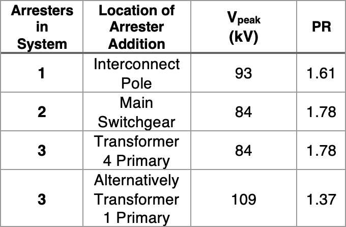
Sequentially adding the switchgear arrester, the final transformer arrester then results in the following protection ratios:
![]()
It is notable that the peak voltage at transformer 1 is 91 kV while the peak voltage at transformer 4 is 86 kV. The peak transformer secondary voltage at transformer 1 is 23 kV and 21 kV for transformer 4 without the SPD at the inverter input, which is well within the transformer’s capability.

PV Inverter SPDs
When the inverter is in service, the low voltage AC system is protected by the inverter’s Type II SPD located at the inverter’s incoming AC section. Since the voltage surge at this point in the system is approximately 20 kV, and the inverter is rated for 2.5 kV it is justified to select AC SPDs at each inverter’s output as recommended. The inverter also includes a Type II DC SPD located on each of the DC inputs. Lightning strikes on the PV field itself are modeled similar to that of the AC side.
The following table summarizes the results of the inverter voltage surges.
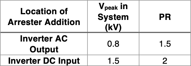
In this typical system, the DC collector grid includes a network of DC combiner boxes with average cable length of 400 ft (122 m) from combiner to inverter. While combiner level SPDs are recommended, they were not used in this application and the resulting voltage surge at the combiner boxes is 2.2 kV, which is within the system’s capability.
Results
It is apparent that a single arrester at the interconnect pole can protect the equipment but is insufficient to pass the protective ratio criteria. However two or more arresters in the system easily provide adequate protection, though there are diminishing returns by adding additional arresters. It is also apparent that AC SPDs are required at the inverter AC output since the power electronic equipment is not rated to withstand voltage surges that are similar to that of a transformer. Several common questions exist surrounding placement, rating and quantity of arresters in this design configuration. These are evaluated below.
Alternate Design Configurations
This section evaluates common alternate configurations of the same basic PV generation that employ fewer arresters, alternate ratings and alternate arrester locations.
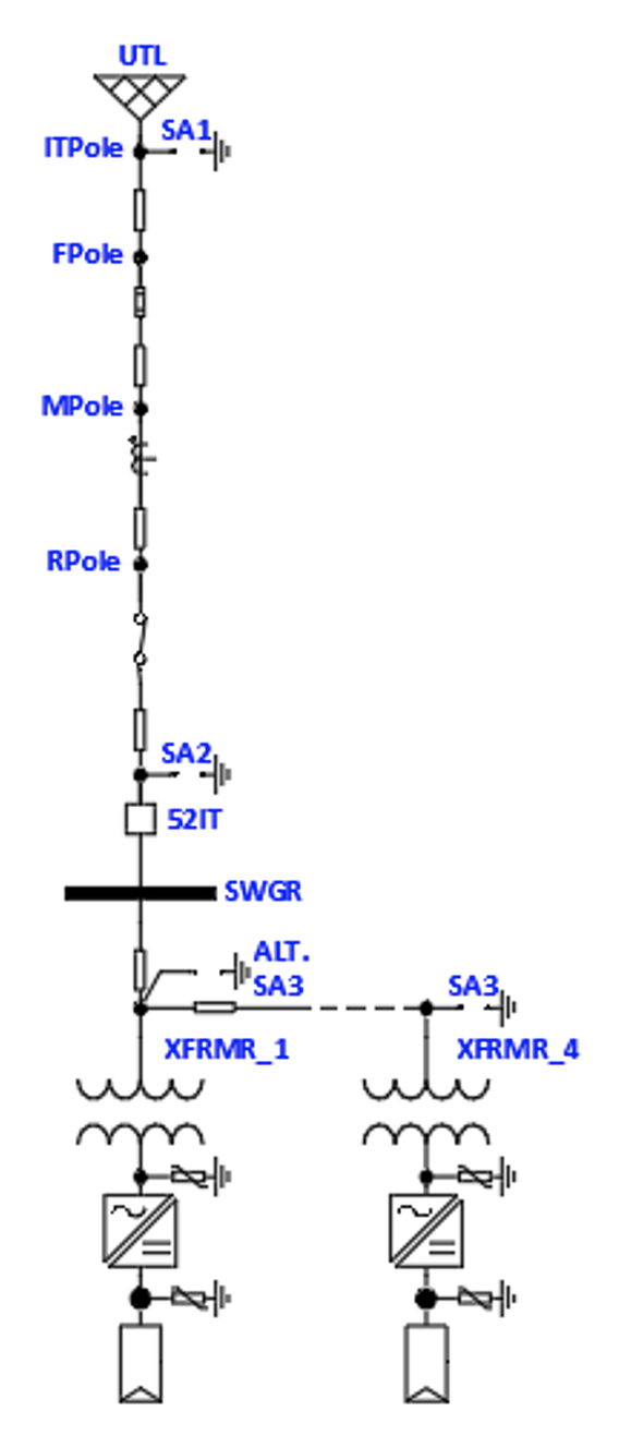

The most common alternate configuration is to remove the multiple pole- mounted arrester system and install a single set of arresters at the interconnect pole. Traditionally, the main switchgear includes a set of arresters and a single set of arresters is placed at either the first or the last transformer in the collector grid.
Transformer secondary arresters and DC arresters are recommended at the inverter skid and are commonly applied. It is apparent that utilizing an interconnect arrester with an MCOV rating greater than the system L-L voltage will not pass the protective criteria (as previously indicated). Therefore, to use a single arrester set at the interconnect pole an alternate arrester rating is required. In this case, with the utility system being solidly grounded, the traditional arrester rating would be 30 kV and 24.4 MCOV. Using this selection, the system is protected.
It is notable that placing the transformer arrester closest to the incoming overhead line adequately protects transformer 1 but transformer 4 experiences much higher voltages. In this case, transformer 4 is still protected, however if the incoming line arrester was increased to 45 kV 36.5 kV MCOV, transformer 4 would experience 133 kV and a PR of 1.13. This brings to light a key decision point. In order to economize the arrester design, the arresters must be sized according to the system grounding configuration and the projected operating modes. In cases where the utility system is solidly grounded, and the PV system is not required to island the collector system, the arresters can be sized for a solidly grounded system and less arresters can be used. However, if the system is intended to island, and the collector system during island mode is not effectively grounded, the arrester ratings must increase to avoid Temporary Overvoltage (TOV) damage. This would increase the arrester ratings, and may result in additional arresters being required to bring down the voltage surge and increase the PR. In the evaluated cases, the optimal location for the collector grid is at the end of the cable system on the last transformers primary. The transformer secondary voltages are within the transformer systems ratings in each case.
![]()
As previously noted, the inverter AC output requires a Type II SPD to protect the power electronics. In all cases, the transformer primary arrester is by itself insufficient to protect the inverter. The remaining design alternative is to add DC SPDs within the combiner boxes in addition to the DC SPDs required at the inverters. Utilizing SPDs at both inverters and combiner boxes results in a reduced voltage surge at both the inverter and the combiner yielding 1.2 kV and 1.5 kV surge voltages respectively. The addition of combiner SPDs may be required if metering equipment is located in the combiners and a lower surge voltage limit is justified.

Conclusions
As with most designs, many different solutions are available to address lightning protection concerns. Careful evaluation of the system and its grounding methodology must be undertaken to ensure proper insulation co-ordination.
Specifically, the following items should be considered:
1. Confirm system grounding and apply surge arresters and SPDs with ratings appropriate for the service voltage. This must include both island mode cases (if applicable) and normal mode.
2. Performing an insulation co-ordination study to determine the proper SPD and arrester locations utilizing standard design templates can result in overdesign and increased costs.
3. Locate the collector grid arrester at the last transformer in the collector.
4. Provide inverters with Type II SPDs on AC output and DC input.
5. Evaluate the DC system including combiner boxes and, if needed, apply SPDs specifically designed for PV systems at combiners.
References
[1] Littlefuse, “Surge Protection for Photovoltaic Systems,” 2019.
[2] J. Das, Transients in Electrical Systems, McGraw Hill, 2010.
[3] NFPA, Standard for the Installation of Lightning Protection, 2014.
[4] e. a. Nor Izzati Ahmad, “Analysis of Lightning-Induced Voltages Effect with SPD Placement for Sustainable Operation in Hybrid Solar PV-Battery Energy Storage System,” 2021.
[5] J. Woodworth, “Understanding Temporary Overvoltage Behavior of Arresters,” 2017.