Insulators for high voltage outdoor applications are often subject to rain, pollution and salt fog. One of the most effective ways to evaluate their performance under these conditions is by testing them under simulated such conditions in a laboratory. The behavior of porcelain and glass insulators has been well investigated for both AC and DC and there is now growing demand for pollution testing of composite type insulators.
However there is still no standardized pollution test procedure available for composite insulators. Since surface hydrophobicity is a key property of these insulators, the procedures used when testing glass and porcelain are not directly transferable. The solid layer method, in particular, seems a problem since applying a conductive layer to a composite insulator surface requires destroying its inherent hydrophobicity. In a typical salt fog test of ceramic insulators, surface properties do not need to be changed but can be left as in their original new condition from the factory.
This edited contribution to INMR by Heiko Jahn and Wolfgang Manzke of KEMA Labs in Mannheim, Germany describes experience with salt fog tests conducted in recent years on composite insulators. They also propose a procedure that provides reliable results without destroying the initial hydrophobicity of the composite insulator being tested.

Definitions
Sometimes, certain terms can have different meanings that are understood only given the correct context. One of these is ‘salt fog test’. While high voltage testing laboratories understand it as a test on insulators with salt fog and voltage applied, material test laboratories will understand this as a corrosion test according to IEC 60068. Moreover, when electrical test laboratories talk about salt fog testing, different products can be the subject of interest, e.g.:
• Salt fog pollution test on glass or porcelain insulators according to IEC 60507;
• Tracking and erosion test on composite insulators according to IEC 62217;
• Weather ageing test on surge arresters according to IEC 60099-4;
• Salt fog test on cable terminations according to IEC 61442/
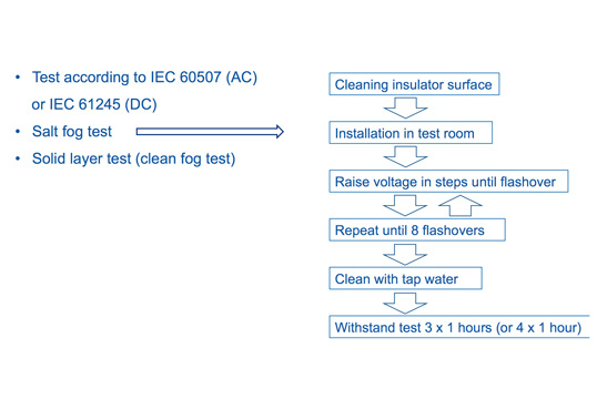
Here, the salt fog test is understood to be a pollution test with a general test layout according to IEC 60507 (2013-12) Ed. 3.0 for AC or according to IEC TS 61245 for DC.

Salt Fog Test Procedure for Glass & Porcelain Insulators
Besides applied voltage, the general procedure for AC and DC is the same. After careful cleaning, a pre-conditioning procedure is carried out. The insulator is then sprayed with salt fog and test voltage follows a defined increase and decrease method, creating pollution flashovers. These flashovers are intended to remove any grease or dirt from the surface, which be have left over after the first cleaning. After 8 flashovers, the pre-conditioning of the insulator is complete and the insulator surface is considered as clean and ‘wettable’.
After pre-conditioning, the insulator is in a defined initial state and reproducible results are expected in the salt fog withstand test that follows. The withstand test consists of a series of 3 individual tests each with 1 hour duration under salt fog and defined test voltage. The concentration of salt in the water spray is defined in steps. If a flashover occurs on the insulator during an hourly test, a fourth one-hour test is done to complete the test series. In the event of a second flashover, the insulator fails the test.
As stated, this standard test procedure refers specifically to glass and porcelain insulators and indeed was optimized to evaluate behavior of such insulators, mainly their shed profile. These procedures cannot be transferred to composite insulators where hydrophobicity is a key property of their housing material and provides advantages over glass and porcelain. Therefore, a relevant test procedure must ideally incorporate this property without degrading it using special pre-conditioning.
Over recent years, the test laboratory in Mannheim has received different client specifications. Some completely skip pre-conditioning and start directly with the hourly tests, i.e. 3 x 1 hour are tested with specified salt level and voltage applied. The result is predictable, namely a passed test. Other specifications request pre-conditioning by applying a kaolin layer on the surface to destroy hydrophobicity. Such a layer cannot easily be penetrated by low-molecular weight (LMW) components of the silicone housing material. Therefore, it remains hydrophilic for a long time.
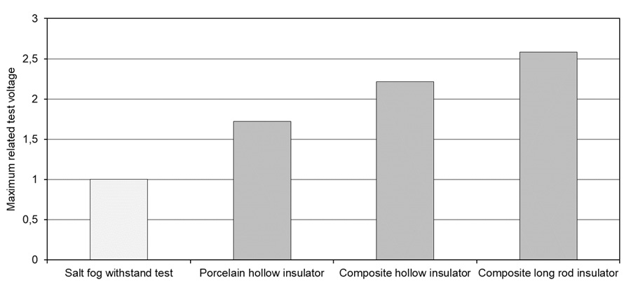
When a standard procedure (according IEC 60507 (2013-12) Ed. 3.0 or IEC TS 61245 (2015-03) Ed. 2.0) is applied, the flashover procedure during pre-conditioning requires a voltage source with a high range of variation if the insulator being tested is not as hydrophilic as glass or porcelain. This means that, in the case of composite insulators, flashover voltage is clearly higher than for ceramic insulators because of surface hydrophobicity, which largely prevents leakage current. Fig. 1 compares AC flashover voltage for different types of insulators during a salt fog test according to IEC 60507 (2013-12) Ed. 3.0 for the first flashover during the pre-conditioning procedure at maximum salinity of 224 kg/m³.

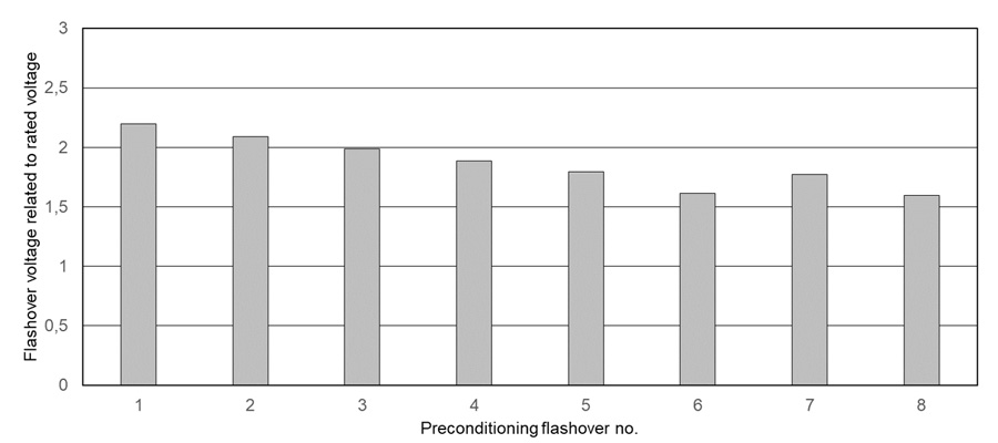
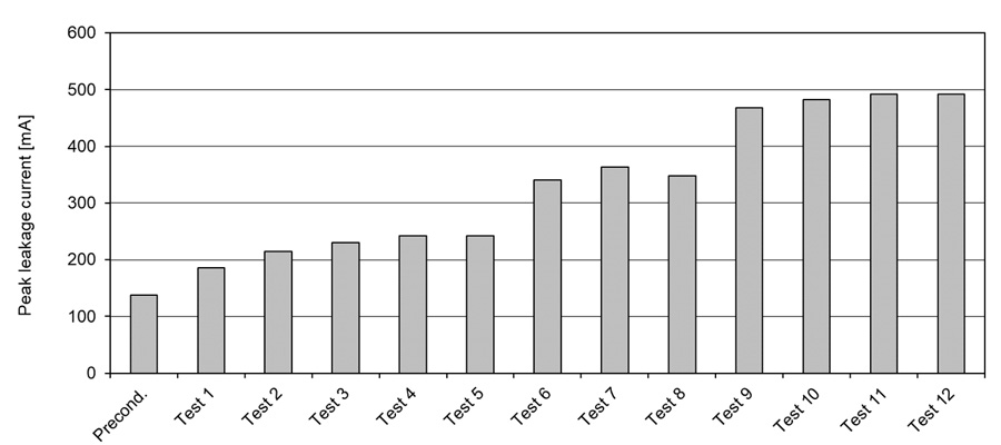
After the first flashover, the flashovers that follow occur at reduced voltages (see Fig. 2). However, voltage levels required to achieve the first as well as the following flashovers can significantly exceed maximum permissible operating voltage of the object being tested. Given this, some devices cannot be tested this way. On surge arresters with varistors, for example, applied test voltage cannot exceed maximum operating voltage. Similarly, other high voltage devices, such as bushings, cable terminations or instrument transformers, cannot operate at elevated voltages without risk of damage. Therefore, a different test procedure needs to be applied to such devices. In addition, applicable test voltage is limited to approximately 600 kV since the distance between spray nozzles and test object is fixed at 3 m, i.e. flashover between the nozzles and the test object’s high voltage electrode can occur.
In summary, standardized test procedures for pollution layer testing, as described, are not directly transferable to composite insulators. To evaluate their pollution performance under salt fog conditions, a revised test procedure is required.
Customized Salt Fog Tests
Application of Standard Test Procedure
Despite the obstacles mentioned above when testing composite insulators, many customers insist on applying the same standardized test procedures used for ceramic insulators, given that there are currently no standardized procedures for composite types. But this is only conditionally feasible. The pre-conditioning process does not achieve the goals intended in the standard, i.e. reducing hydrophobicity to some well-defined state is not possible.
To limit required test voltage during the conditioning procedure, the insulator is sometimes pre-conditioned in sections, as permitted in the standard for ceramic insulators. To prepare the sections, additional electrodes of metal foil are sometimes installed on the insulator. This can cause problems when the device under test contains internal parts with different field grading. In such cases, high radial field strength can stress the insulator housing.
A customer-specific modification is application of the standardized salt fog test but without a pre-conditioning process. In this case, test duration is only three times 1 hour. Hydrophobicity depends on insulator design and is hardly reduced, i.e. only small current can be measured, which for AC tests is caused by the capacitance. In such cases, many insulators will pass and the question arises whether the test is effective under these conditions.

Test Procedure According to TERNA
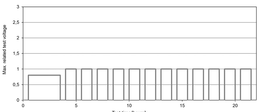
The Italian transmission system operator, TERNA, specifies a salt spray test method applicable to high voltage devices with composite insulators and without increased voltage levels that could prove critical for the laboratory or for the device under test. The test is based generally on the salt fog procedure of IEC 60507 but with the following adjustments (see Fig. 3):
• the pre-conditioning procedure of IEC 60507 is replaced by a 3 hour pre-stress with 80% of rated voltage;
• the withstand test of 3 times 1 hour is replaced by 12 times 1 hour;
• the criterion to pass the test is that at least 8 hours pass without flashover.
The time between pre-conditioning and the hourly tests is limited to 30 minutes and the time between the hourly tests is also limited to a maximum of 30 minutes to avoid regeneration of surface hydrophobicity. The highest required voltage in this procedure is the rated voltage of the insulator (for AC usually Ur/√3), i.e. significantly lower compared to standardized salt fog pre-conditioning (see Figs. 1, 2 & 3).
Based on many years of experience in pollution testing and after a large number of tests with the procedure described above, it is considered useful for salt fog testing of insulators with hydrophobic surfaces. One of the advantages of this procedure is that it is also applicable to devices with limited withstand voltages, such as surge arresters. Laboratory experience has shown that, in most cases, an increase in leakage current can be observed, i.e. hydrophobicity is at least partially lost. However, in the event of complete loss of hydrophobicity, a well-designed insulator shows stabilized leakage current and does not flashover (see Fig. 4).
In principle, this procedure is also suitable for direct voltage tests. The nearly constant test voltage during the procedure is advantageous for preparation of the test circuit since it has to be optimized only for a single operating point. This saves testing time and cost.
Compared to the solid layer test procedure, where an adhesive pollution layer applied beforehand completely removes hydrophobicity, this salt fog test procedure does not destroy this key property of the housing material. It therefore better reflects actual condition of the grid under extreme environments. The test includes the advantages of more hydrophobic materials, which are expected to show lower leakage currents in service.

Experience with This Salt Fog Test Procedure
Several examples of recent tests demonstrate performance of this test procedure. Since the laboratory measures leakage current continuously and records the highest value every minute, every one-hour record provides 60 measured peak values. This allows recognizing whether a loss of hydrophobicity occurred during the test. Of course, in case of AC there is a small bias due to the capacitive current. Figs. 5 to 7 depict leakage currents measured on different insulators with the described test procedure applied. The insulator in Fig. 5 was hydrophobic during the entire test time.
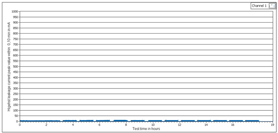
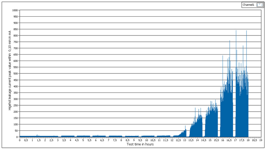

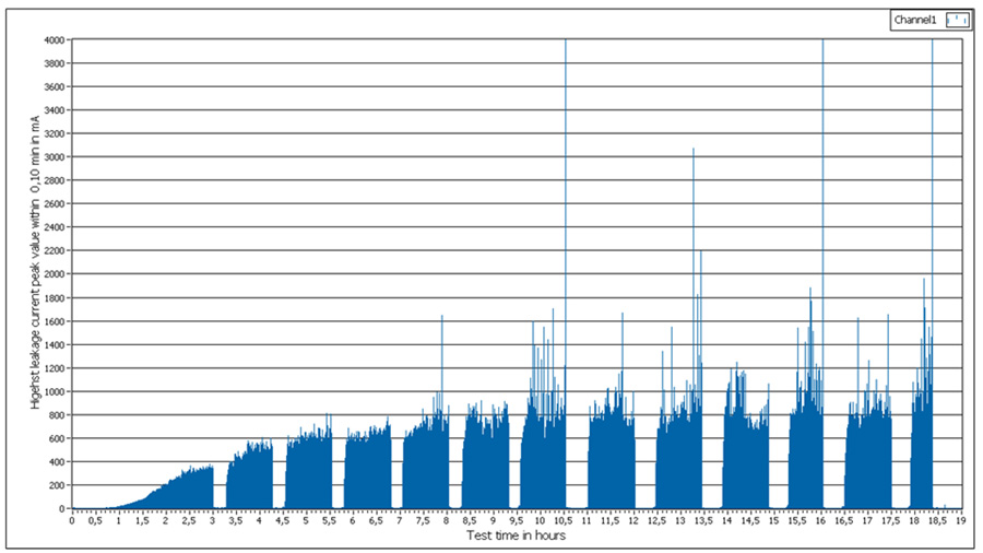
Fig. 6 shows results for an insulator that lost hydrophobicity during the hourly tests but without flashover. The weakest insulator in this test series already showed loss of hydrophobicity during the pre-conditioning phase. Later, 3 flashovers were detected during the hourly tests (see Fig. 7). However, this insulator still passed according to the specification.
Based on these measurements, it can be concluded that this test procedure neither overstresses insulators nor is too easy to pass for composite insulators with hydrophobic surfaces. Figs. 5 and 6 clearly indicate that the 3 hour test according to IEC 60507 (2013-12) Ed. 3.0 and IEC TS 61245 (2015-03) Ed. 2.0 is not sufficient to properly evaluate pollution withstand of composite insulators.
Of course, there are salt fog tests for composite insulators and devices, as already mentioned, and the question arises whether these tests cover pollution behavior, evaluated with the salt fog test described in clause 4.2. They do not. The reason is that the test procedures are different not only in intention for testing but also in applied test parameters. Therefore, test results of a 1000 h tracking and erosion test, where loss of hydrophobicity sometimes occurs after hundreds of hours, cannot be transferred to a pollution test. The tracking and erosion test was created to evaluate composite insulator design and choice of proper housing material and does not simulate severe environmental conditions.
Some additional options for this test are still being discussed. An initial idea, for example, is to increase the voltage during the pre-conditioning phase from 80% of test voltage to 100%. This better reflects operating conditions. A second option could be introducing evaluation of the state of hydrophobicity both prior and after the pre-conditioning phase, following the procedure of IEC TS 62073 Annex C. In the event there is no evidence of hydrophobicity loss, one more hour of pre-conditioning could be added.
Summary & Conclusions
Salt fog testing of composite insulators with hydrophobic housing materials remains a challenge. There is still no standardized test procedure that incorporates the hydrophobic properties of the housing. The range of different client-specific test procedures can therefore vary between easy stress, with no pre-conditioning, up to complete disabling of hydrophobicity.
The Terna procedure discussed above offers an acceptable compromise. It incorporates the hydrophobic properties of the housing material while stressing the insulator long enough to identify any possible weaknesses in design or choice of material. In general, this procedure could be used for both AC and DC insulators. Due to choice of test parameters, layout of the test circuit is simplified and does not need to be changed during the test. One disadvantage of this test procedure, however, is duration, which requires working in shifts. However, experience suggests that the advantages outweigh this drawback.
References
[1] CIGRÉ Report 158 by TF 33.04.01: Polluted Insulators: A Review of Current Knowledge, June 2000
[2] IEC 60068-2-11 (2021-03) Ed. 4.0: Environmental testing – Part 2-11: Tests – Test Ka: Salt mist
[3] IEC 60068-2-52 (2017-11) Ed. 3.0: Environmental testing – Part 2-52: Tests – Test Kb: Salt mist, cyclic (sodium chloride solution)
[4] IEC 60507 (2013-12) Ed. 3.0: Artificial pollution tests on high-voltage ceramic and glass insulators to be used on a.c. systems
[5] IEC 62217 (2012-09) Ed. 2.0: Polymeric HV insulators for indoor and outdoor use – General definitions, test methods and acceptance criteria
[6] IEC 60099-4 (2014-06) Ed. 3.0: Surge arresters – Part 4: Metal-oxide surge arresters without gaps for a.c. systems
[7] IEC 61442 (2005-03) Ed. 2.0: Test methods for accessories for power cables with rated voltages from 6 kV (Um = 7,2 kV) up to 30 kV (Um = 36 kV)
[8] IEC TS 61245 (2015-03) Ed. 2.0: Artificial pollution tests on high-voltage ceramic and glass insulators to be used on d.c. systems
[9] Fourmigé, J.-M.; Noël, M.: Testing Methods for Performance Prediction of Outdoor Insulation Housings. 1996 IEEE Annual Report – CEIDP, Proc. Pp. 451-454, San Francisco, October 1996
[10] Jahn, H.: On the Evaluation of Material-Specific and Technological Influence Factors on the Hydrophobicity and Erosion behaviour of Silicone Rubber Surfaces. Doctor Thesis, TU Dresden, 2003
[11] Büchner, H.; Schmuck, F.; Zanetti, A.; Zingg, A.; Bärsch, R.; Jahn, H.: Impact of Filler to Silicone Rubber Basing on RTV-2- and LSR-Systems. 10th ISH; Proceedings, Vol. 3, pp. 209-214, Montreal, Aug. 1997
[12] IEC TS 62073 (2016-02) Ed. 2.0: Guidance on the measurement of hydrophobicity of insulator surfaces