As power demand continues to grow and the integration of renewable energy sources increases, the vulnerability of power equipment to transient overvoltages becomes a critical concern. Surge arresters are indispensable components of power systems and play a vital role in protecting sensitive equipment from the damaging effects of voltage surges caused by lightning strikes, switching operations or faults.
Over the years, surge arrester technology has evolved significantly, driven by the need for improved performance and enhanced reliability. Although manufacturers have developed innovative designs and materials to meet the increasing demands placed on arresters, the complex nature of surge phenomena and diverse operating conditions make it challenging to predict performance of these protective devices.
Short circuit testing provides valuable insight into behavior of surge arresters under high-current fault conditions, which are particularly relevant for evaluating their effectiveness in diverting surge currents away from sensitive equipment. By subjecting arresters to controlled fault currents, engineers can observe their response characteristics, including structural stability under short-circuit circumstances.
This edited contribution to INMR by Ankit Saboo, Elektrolites (Power) in India presents an analysis of experience-driven improvements in arrester performance through short circuit testing, including in methodologies, test set-ups and measurement techniques employed to evaluate an arrester’s capability to withstand and respond under short-circuit situations. Ultimately, experience-driven improvements in surge arrester performance can aid in developing more robust and efficient surge protection solutions and help in optimizing surge arrester designs as well as performance characteristics.

Short-Circuit Testing of Arresters
Fortunately, failure of an arrester is not a common event. However, if it does occur, the arrester must not damage nearby equipment and also self-extinguish any flames so that there is no collateral damage.
Possible reasons for failure include:
● Overloading of the active elements by energy or current;
● Moisture ingress;
● Partial flashover of one or several units in a multi-unit arrester caused by external pollution, birds or high overvoltages;
● Thermal instability due to the effect of heavy external pollution;
● High temporary overvoltages;
● Damage to blocks in one or several units due to energy and current discharges which leads to power frequency overload of the remaining part of the arrester;
● Mechanical overloading which leads to electrical failure.
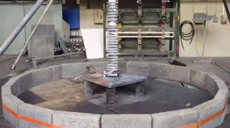
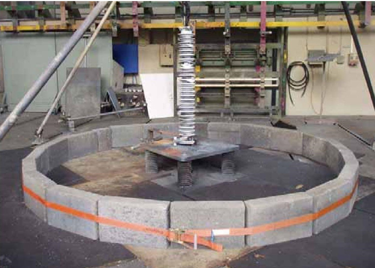
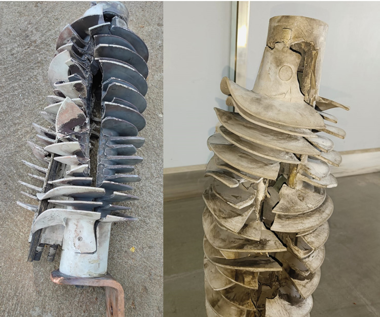
Short circuit tests are destructive overload tests performed to demonstrate that arrester failure does not result in violent shattering of its housing or in any components, potentially causing injury to personnel or damage to nearby valuable assets. Also, it must be demonstrated that all flames are self-extinguished within two minutes. Unfortunately, this terminology could be misleading if compared with short-circuit ratings and tests of other HV equipment such as breakers, transformers, cables, which shall remain fully functional after the respective short-circuit test. The difference between short-circuit testing of an arrester versus other power system equipment is that while other equipment must withstand the short circuit current and still be able to operate after its passing, the arrester must conduct and fail controllably – not violently. It is for this reason that this test is also referred to as the ‘pressure relief capability test’.

Types of Arresters
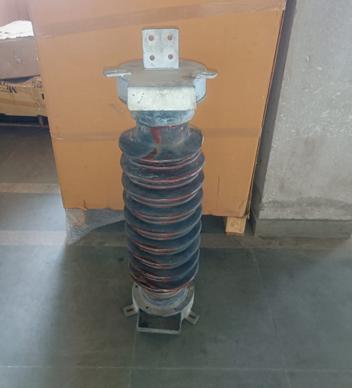
1. Design A: Also referred to as ‘hollow-core’ or ‘tube’ design)
a. Made with a polymeric material molded over a hollow FRP tube;
b. Made using a porcelain hollow-core insulator
2. Design B: Made almost exclusively out of a polymer. (Porcelain and cast-resin variants are available but discouraged and not common)
a. Wrap Design – made by wrapping ZnO assembly with FRP cloth/resin and other materials and then molding polymer over this. It can also be made using a pre-molded polymeric housing slipped over the ZnO and FRP resin assembly, along with some sealing system.
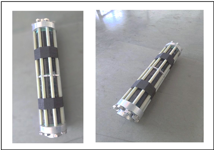
b. Cage Design – made by forming a cage of FRP structure of rods and flats around the ZnO assembly and then molding polymer over this.
c. Cast Resin – made using cast-resin insulation over the ZnO assembly. This technology is used only rarely and not covered here.
d. Other designs involving filament winding, also not covered here due to limited experience.
The two fundamentally different types of arrester design, designated Design A and Design B, require different test procedures.
Design A arresters have internal gas channels that occupy more than 50% of the total internal volume. Overloading of such arresters will typically cause high stresses in the gas channel, which may result in complete dielectric breakdown. Such arresters typically have pressure relief devices to quickly vent the built-up pressure from the resulting short-circuit arc and prevent it from reaching a level that could cause violent scattering of the housing.
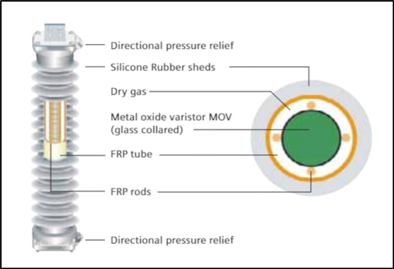
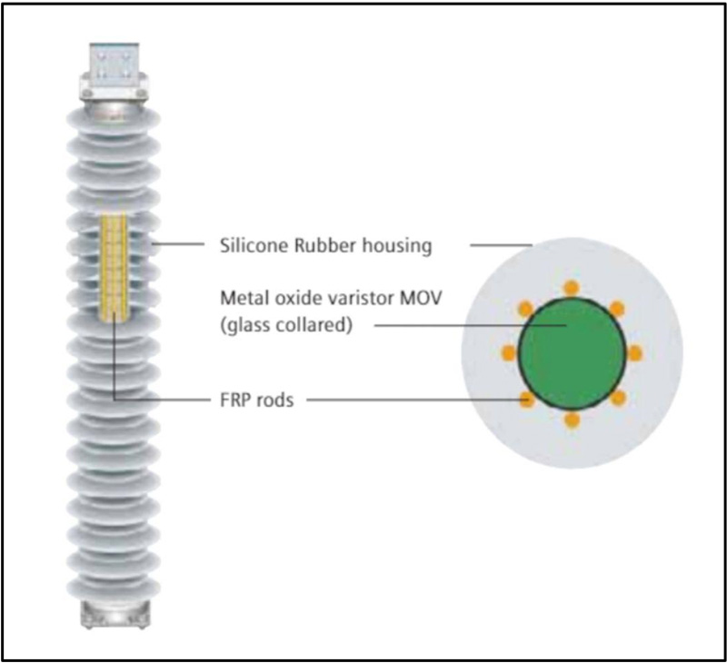
Design B arresters have MO resistor stacks that have no significant exposure to gas. The MO resistors are typically contained in a cage or wrap of fiber-reinforced plastic (FRP) that is subsequently overmolded with or inserted into a housing made of organic material. Overloading such arresters typically results in dielectric failure through the body of the MO resistors or along the MO resistor stack surface within the cage or wrap. The built-up pressure will vent anywhere along the housing or through designated weaker parts of the housing.

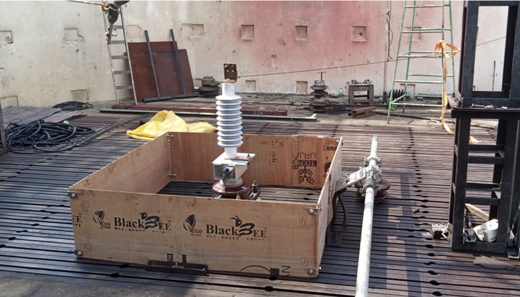
Sample Preparation
Arresters must be tested for the worst-case scenario. Hence, it is important to choose the arrester with the longest housing and highest voltage rating of the design being tested. In such a case, this test will be applicable to all units that have the same design with housing length and rated voltages equal to or lower than the test sample.
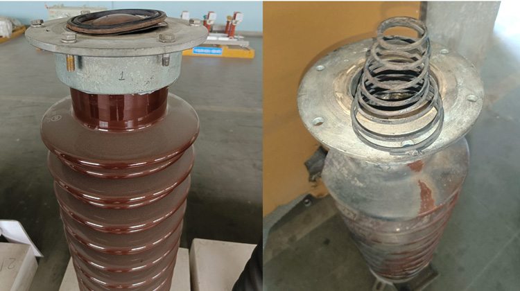
Porcelain-Housed Arresters
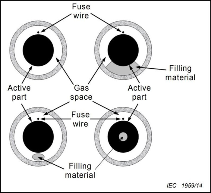
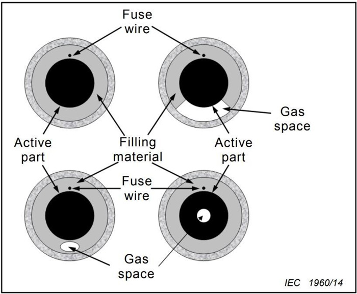
For porcelain-housed arresters – both Design A (most porcelain-housed arresters are Design A) and Design B (seldom porcelain-housed), it is generally agreed that placing a fuse wire in the gas volume to initiate short-circuit along the surface of the resistor column represents the most relevant failure scenario. An exception has to be made only for porcelain-housed arresters of “Design B,” where the pre-failing method could cause less severe test conditions (in case the arc develops in the gas channel and not in the solid material, as intended). Such risk can be accepted for polymeric housings but not for housings made of a brittle material.
Polymer-Housed Arresters
Polymer-housed arresters with composite hollow insulator (‘Design A’ arresters), follow the same rationale as with porcelain-housed ‘Design A’ arresters. However, for polymer-housed arresters with the housing directly applied onto the varistors (i.e. ‘Design B’ arresters), a fuse wire along the varistor surface cannot be accepted because the test would then be unrealistically easy to pass. On the other hand, a fuse wire through holes drilled through the varistors would be too harsh a scenario since it can hardly be imagined that all varistors of a failing arrester will break by puncture. It is therefore justified to specify a pre-failing method as the most reasonable compromise with regard to test severity and realism.
No special preparation is necessary. Standard arrester units shall be used. The arrester units shall be electrically pre-failed with a power frequency overvoltage. The overvoltage shall be run on completely assembled test units. No physical modification shall be made to the units between pre-failing and the actual short-circuit current test.
The overvoltage given by the manufacturer shall be a voltage exceeding 1,15 times Uc. The voltage shall cause the arrester to fail within (5 ± 3) min. The MO resistors are considered to have failed when the voltage across the MO resistors falls below 10 % of the originally applied voltage. The short-circuit current of the pre-failing test circuit shall not exceed 30 A.
The time between pre-failure and the rated short-circuit current test shall not exceed 15 min. The pre-failure can be achieved by either applying a voltage source or a current source to the samples.
Test Evaluation
The test is considered successful if the following three criteria are met:
a) No violent shattering. Structural failure of the sample is permitted so long as criteria b) and c) are met.
b) No parts of the test sample shall be allowed to be found outside the enclosure, except for: fragments less than 60 g each of ceramic material such as MO resistors or porcelain; pressure relief vent covers and diaphragms; or soft parts of polymeric materials.
c) The arrester shall be able to self-extinguish open flames within two minutes after the end of the test. Any ejected part, inside or outside the enclosure, must also self-extinguish open flames within two minutes. A shorter duration of self-extinguishing open flames for ejected parts may be agreed upon between manufacturer and user.

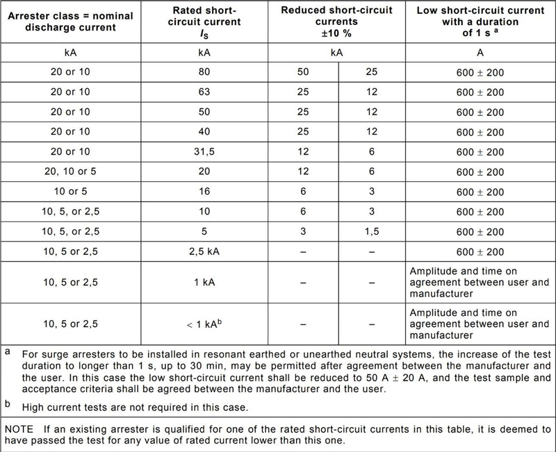
Test Values
As per IEC 60099-4, Fig. 7 shows typical values for the short-circuit testing.
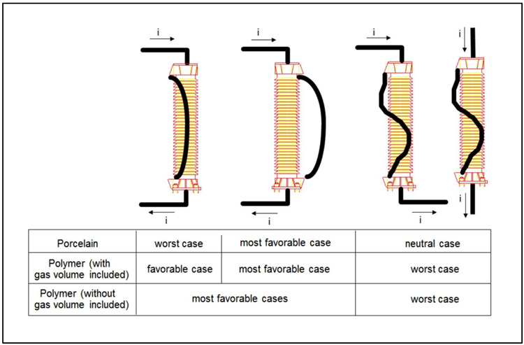
Behavior of Sample During Test & Known Best Practices
Porcelain-Housed Arresters (both Design A & Design B)
Performance of a porcelain-housed arrester in the short-circuit test comes down to its ability to expunge the built-up energy through its vents without letting the structure blow-out either due to cracking of the MOV blocks or any other internal component. Below are key factors that make for superior performance:
1. Strength of the porcelain must be enough to sustain the shock waves without breaking. High alumina composition porcelain ensures better performance in such situations.
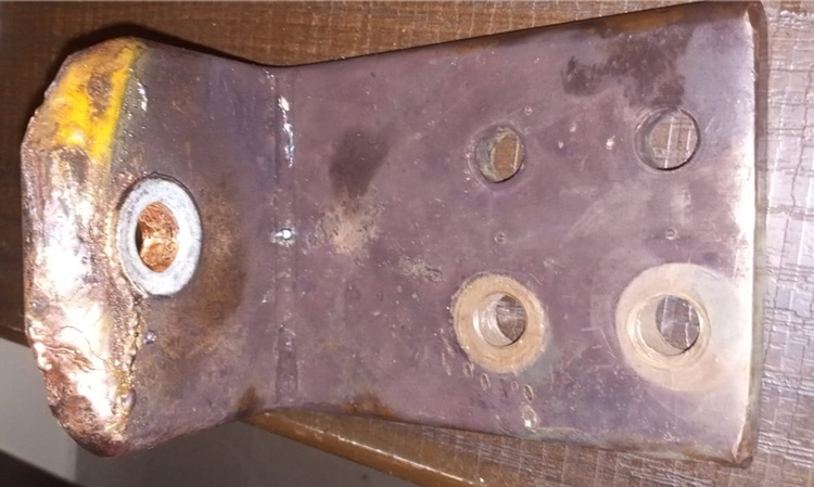
2. Ability of the metal diaphragm to operate quickly without letting too much energy be built-up inside the arrester. Adequately thin and soft material diaphragms, such as those made of annealed copper, have shown superior performance.
3. Straightness and tightness of connections on the HV side with the terminal connector and the flexible copper can make a huge difference in movement of the arrester due to the heavy energy flow. Any angled or weak connection can make the arrester become topped in a certain direction, leading to instability and hence higher chance of failure.
Another notable phenomenon is ‘secondary thermal break’, caused by the extreme thermal stress as a result of the sudden increase in temperature during the venting process. In such a case, the porcelain housing collapses on itself. This is normal and completely acceptable as per the standards.
Polymer-Housed Arresters (Design A)
This follows the same behavior as for a porcelain-housed arrester apart from the insulator being used. In this case, the FRP material plays a huge role in the strength of the sample and hence its short-circuit performance. It has been observed that FRP of density greater than 2.25 kg/mm3 offers significantly better performance compared to lower densities. Of course, the secondary thermal break phenomenon is not relevant here since the temperature behavior of FRP material is different from that of porcelain.
Polymer-Housed Arresters (Design B)
In case of Design B type polymer-housed arresters, the MOV blocks have to conduct since no fuse-wire is used as a bypass. Due to this, the following are key factors that make for a better performance during short-circuit testing:
1. Strength of the FRP structure holding the zinc oxide blocks together. In the case of FRP rods, for example, it has been found that using rods of minimum 10 mm OD for tests up to 40 kA and of 16 mm OD for tests up to 63 kA significantly improves successful performance during short-circuit situations.
2. Number of FRP rods can also make a huge difference in short-circuit performance. When the short-circuit current is passed through the MOV blocks, they have a tendency to push outwards radially toward the FRP rods. Any gaps can lead to blocks being expelled outside the structure and hence failure of the test.
3. Designs that prevent lateral movement of failed zinc oxide blocks have superior performance compared to designs that do not. This could be achieved through using a high-strength winding material across the length of the arrester to prevent the structure from blowing out.
4. Straightness and tightness of connections on the HV side with the terminal connector and the copper flexible can make a huge difference in movement of the arrester due to the heavy energy flow. Any angled connection or weak connection makes the arrester get topped in a certain direction, leading to instability and hence higher chance of failure.

References
1. IEC 60099-4:2014 Ed 3.0 – Surge arresters – Part 4: Metal-oxide surge arresters without gaps for a.c. systems
2. IEC 60099-5:2018 – Surge arresters – Part 5: Selection and application recommendations
3. IEC 60099-10 – Surge arresters – Part 10: Rationale for tests prescribed by IEC 60099-4
4. A3-105_2004 (CIGRE) – Modern ZnO Surge Arresters under Short Circuit Current stresses, test expiriances and critical review of the IEC standard
5. SIEMENS Handbook by Volker Hinrichsen 3rd Edition – Metal-Oxide Surge Arresters in High-Voltage Power Systems Fundamentals