Selecting and qualifying a supplier of polymer insulators is a more complex proposition than most users might imagine. While there are ANSI & IEC standards that govern certain aspects of design and manufacturing, variations defined by each supplier can result in insulators that look different and, more importantly, perform differently. It is therefore important to understand the possible differences and how these can impact desired performance in service.
The edited contribution to INMR by Edward Niedospial, Technical Specialist at MacLean Power Systems offers his insight into how to specify the best materials and how to identify critical details, terminologies and performance criteria that might exceed what is offered in the standards. It also describes the basic composition of a polymer insulator, reviewing the components and various options along with how these options can impact long-term performance.

There are a range of different names used for polymer type insulators, including:
1) composite insulators (made of various elements or components);
2) polymer insulators;
3) non-ceramic insulators (NCIs);
4) synthetic insulators;
5) rubber insulators.
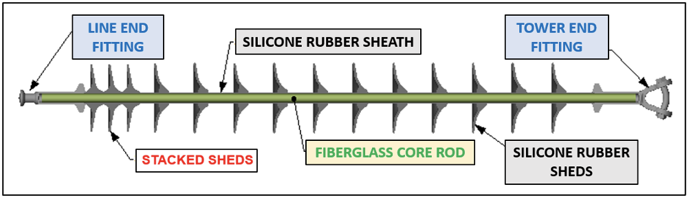
Yet, no matter what they are called, one aspect of a polymer insulator that is consistent across all suppliers is the basic composition, i.e.: core, housing and end connections. While this is true at a generic level, greater insight is needed in order to better understand how polymer insulators are manufactured and how those differences can impact performance.
Composition of Polymer Insulator
1) Core: The fiberglass core rod is the ‘heart’ of the polymer insulator and serves as both primary mechanical and electrical component.
2) Housing: Typically a generic term for the sheath and weather sheds, mostly made of either silicone or EPDM rubber and sometimes a combination of both.
3) End Connection: The end fittings, whether ductile iron or steel, are connected to the core rod and act as the mechanical connections through which system loads are applied through the core rod to the tower. Each insulator will typically have a line end fitting (LEF) and a tower end fitting (TEF).

Mechanical Performance
The core rod combined with the two end fittings make up the mechanical element of a polymer insulator. An insulator is first and foremost a mechanical device, holding the conductor in space and maintaining minimum phase clearances as required by the applied voltage.
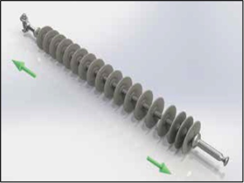
Tensile Applications
• Suspension & Dead-end Insulators.
• Small OD Core Rods [Transmission Class – 16 mm, 22-24 mm, 32 mm, 38 mm and above]
• End fitting geometry governed by Standards (most of the connection ends).
• SML = Specified Mechanical Load = Rated Ultimate load.
• RTL = Rated Tensile Load = Working Load [standards define as 50% of SML but can vary by customer specification / definition for RTL ratings).
• Strength Rating not impacted by length of insulator.
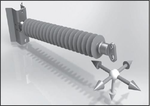
Cantilever Applications
• Line Post & Braced Post Insulators.
• Larger OD Core Rods [Transmission Class = 2.5 in (63 mm), 3.0 in (76 mm), 3.5 in (88 mm) and above].
• End Fitting geometry somewhat defined by standards and typically requires some form of base connection to tower.
• Post applications can be horizontal, vertical, underhung, and braced.
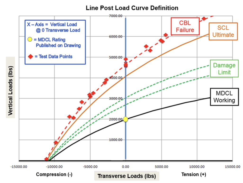
• SCL = Specified Cantilever Load = Ultimate Cantilever Load
• MDCL = Maximum Design Cantilever Load = Working Cantilever Load.
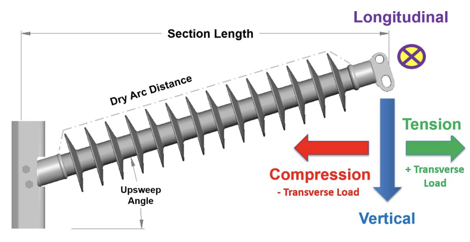
• Multi-Axis Combined Loading – Vertical + Transverse + Longitudinal.
• Post Applications require a Load Curve to define mechanical capacity.
Fact: As the post gets longer, it becomes weaker (less cantilever capacity).
Fact: In a braced post application, the most common breaking limitation is dictated by the hardware and end fittings, not the core rod diameter. Hence the need for engineered solutions and testing.
Electrical Performance
Once an insulator is mechanically stable, its second function is to provide the insulating properties required. While the fiberglass core is the primary insulating medium, only when it is fully enclosed within a rubber housing is it capable of performing the electrical functions of the application. The most common material used to protect the fiberglass core rod from moisture, contaminants and other environmental stress is silicone rubber.
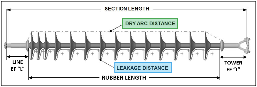
This housing consists of a sheath and weathersheds, which can be applied as a single body, as jointed bodies or using a modular process whereby the sheds are added separately to the sheath. No matter how the rubber is applied, the key dimensions to focus on when designing and comparing different insulator designs are: Dry Arc Distance, Leakage (Creepage) Distance, Rubber (Insulating) Length, and Section / Connection Length.

Critical Dimensions Pertaining to Electrical Performance:
Dry Arc Distance
Sometimes referred to as the arcing distance or flashover distance, it measures the distance metal-to-metal, up to the first shed, across all sheds and then from the last shed back to the end fitting. In simple terms, it is the air gap across the length of the insulator.
• This will dictate the Dry Flashover & Withstand electrical values and CIFO (Critical Impulse) values;
• Wet Flashover & Withstand (performance of the insulator when wet and under continuous water application) are determined by dry arc distance but also impacted by leakage distance and shed profile;
• All values above are statistically derived by each manufacturer and based on testing in a laboratory environment. The FO and Withstand values are nominal values with a +/- range;
• Dry Arc Distance is a measurable dimension that is fixed and can be used to compare different designs.
Leakage Distance
Sometimes referred to as creepage distance, this is the distance across the surface of the housing (all sheds) from line end fitting to ground end fitting.
• Protects the insulator from the impact of contamination and harsh environment;
• Leakage is another dimension to compare different designs.
Section Length
Connection length is the distance from line to tower connection of the insulator.
• Subject to change based on type of end fittings used;
• While section length is critical, it is second to Dry Arc Distance when comparing electrical performance of different insulators.
Rubber Length
Also known as minimal insulating length, this is the distance of the rubber housing, from end fitting to end fitting along the X-axis.
• This dimension is determined by the manufacturing equipment. Once defined by a supplier, it is not likely to change;
• Rubber Length is a reference dimension and less critical to performance.
Fact: The best way to increase dry arc distance is to increase section length. Each added inch (25.4 mm) of section length increases dry arc distance by an inch (25.4 mm). A one for one relationship.
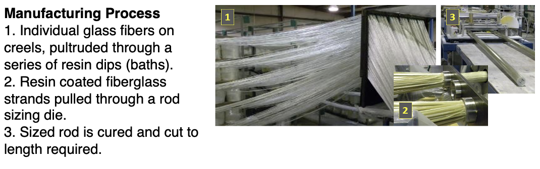
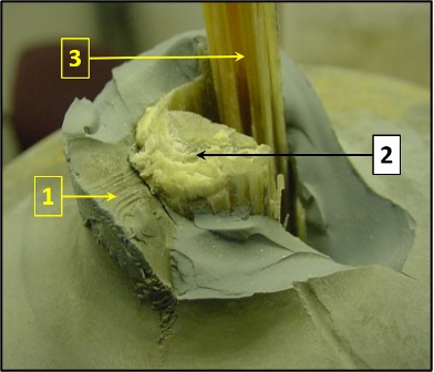
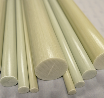
Fiberglass Core Rod
The fiberglass core rod is the primary mechanical as well as electrical component, making it the ‘heart of a polymer insulator’. The core rod is made up of thousands of individual glass fibers (also known as rovings) bonded together by an epoxy resin.
Fiberglass Core Composition
The fiberglass core rod is made up of resin-impregnated fiberglass. However, type of resin and fiberglass, along with percentage of glass versus resin, is not defined in the standards. Rather, these are left to the rod manufacturer to define. For example, the decision on what glass and resin to use could depend on intended mechanical and electrical performance of the rod. A smaller OD core rod is primarily used for tensile applications, whereas a larger OD rod is required to meet higher compression and cantilever mechanical loads.
Fiberglass “Fiber” Options
Both options meet or exceed the tests defined in ANSI and IEC Standards
1) E-Glass = Electrical Grade Fiberglass
• Primarily used today to manufacture line post core rods;
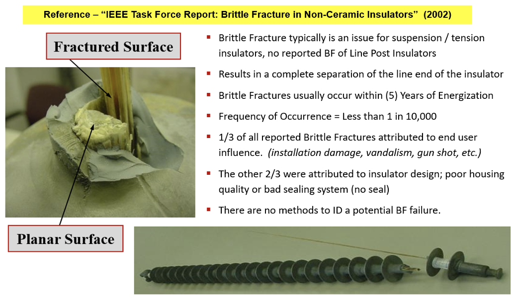
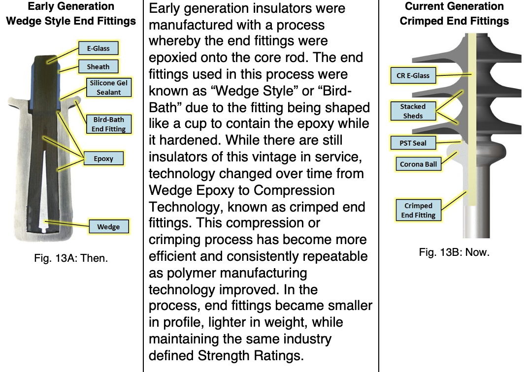
• Used on early generation polymer types (suspension);
• Susceptible to brittle fracture (on suspension applications).
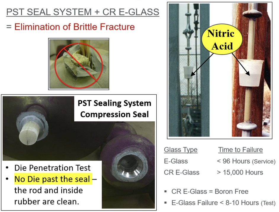
2) Corrosion Resistant E-Glass (CR-E or ECR) = Boron Free Fiberglass
• Boron Oxide removed from composition of glass fibers;
• Designed to eliminate brittle fracture;
• Same manufacturing process as standard E-Glass;
• Mechanically & electrically equal to E-Glass.
Resin Options
All options will meet or exceed the tests defined in ANSI and IEC standards.
1) Epoxy Resin = high electrical insulation, mechanical strength and resistant to chemicals. But the finished rod is potentially more brittle, impacting the crimping process. It can also experience issues due to the high temperatures used during the next step in insulator manufacturing, i.e. application of rubber housing.
2) Polyester Resin = lower cost resin, but also less chemical resistant. This is better suited for marine applications.
3) Vinyl Ester / Epoxy Blend = combines the best features of polyester and epoxy resins. The combined material (hybrid) is stronger than polyesters and more heat resistant than epoxies, making it ideal both for application of rubber and crimping.
Fiberglass Core Rod: Make or Buy?
Some polymer insulator manufacturers make their own rods while others purchase them as finished goods from a 3rd party supplier. In most cases, even those suppliers that manufacture their own rod have a 3rd party supplier approved as back-up. It is good industry practice to have multiple approved suppliers in case of emergency or for expanded capacity needs.
Typical Range of Core Rod Diameter by Application
◊ Tension Application (Suspension Insulators)
• 16 mm – 38 mm core diameters are the most common sizes.
◊ Cantilever / Compression Application (Line Post Insulators)
• 1.5 – 3.5 in core diameters are the most common sizes;
• Hollow core tubes.
Comment: Manufacturing the fiberglass core rod is a messy process and therefore best performed in a plant separate from manufacture of the finished polymer insulator. Even those manufacturers that produce their own rods typically do so in a separate factory.

Evaluating Quality & Performance Pertaining to Core Rod
• What is performance of rod (self-manufactured or purchased externally) with respect to the standard tests?
• How is incoming (self-produced/3rd party) rod inspected and approved for production?
• Does the manufacturer have lot control? Are they able to trace rods all the way through production to the completed polymer insulator?
• Do they use “Boron Free” core rod for suspension applications?
Rubber Housing & Weather Sheds
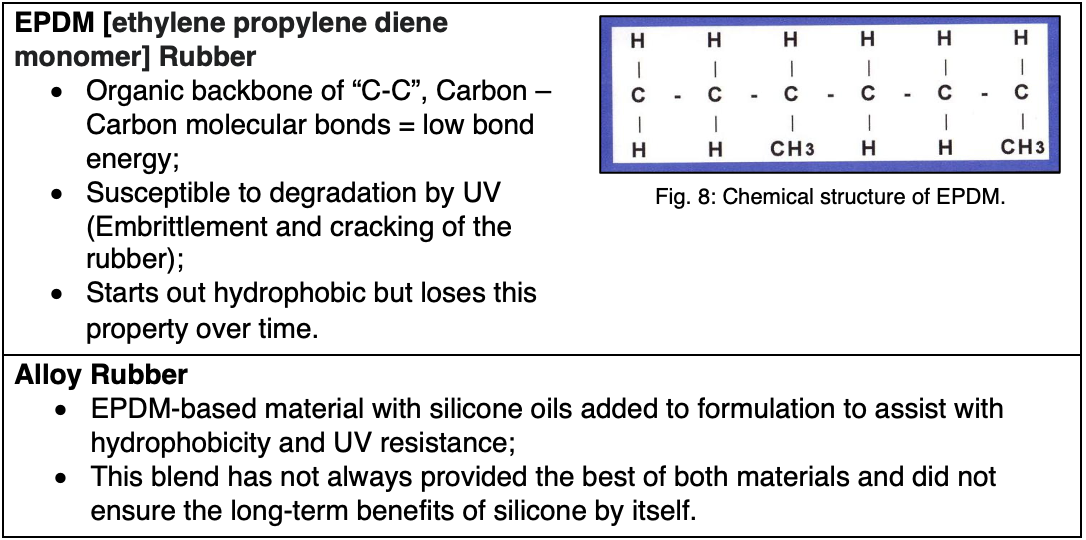
The function of the rubber housing, in conjunction with weathersheds, is to protect the core rod from the impact of the environment (including salt, dirt, dust and moisture) where insulators are put into service. Historically, rubber housings have been made of different materials, e.g. silicone, EPDM, and alloy materials.
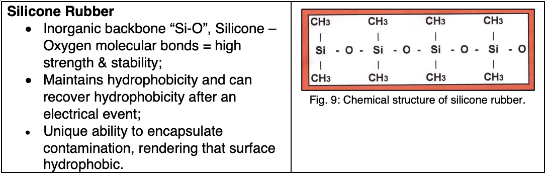 However, not all silicone rubber materials are the same. Rather, quality and performance of silicone material is based on formulation and on manufacturing process by which the rubber is vulcanized, i.e. transitioned from the raw to the cured state.
A. Silicone Formulation
Each supplier uses a proprietary silicone formulation as part of their insulator design and which is a mixture of insulating materials, compounded as required by that supplier.
Fact: Because a material is silicone does not guarantee quality and proven performance. Instead, this will vary from formulation to formulation. When asked, each supplier should be prepared to discuss this and have test documentation to verify that their formulation will meet user expectations.
Specific % of each component in the formulation is unique to each supplier and can vary in performance. Too much or too little of one component of the formulation could be the difference between satisfactory and poor performance.
Basic Components of Silicone Formulation
1. Base Material = Elastomer or pure silicone is the base polymer that is the backbone (Si-O) of the formulation, responsible for hydrophobic performance, i.e. hydrophobicity over the life of the insulator, rate of hydrophobicity recovery and ability to encapsulate contaminants);
2. ATH [Aluminum Tri-Hydrate] is the arcing resistance agent in the formulation intended to improve tracking and erosion properties;
3. Curing agent is the cross-linking catalyst that triggers the vulcanization process, which begins to cure the silicone into its finished state;
4. Colorants: Silicone is typically clear and grey coloring is added to the compound;
5. Processing aids / mold release agents: These help material flow in the mold and ensure good release properties;
6. Special Additives / Fillers: These are defined by each supplier.
B. Processing Type
There are different methods of vulcanizing/curing the raw rubber into the finished material.
◊ HTV = High Temperature Vulcanization = a process by which heat is applied to adhere the rubber material to the surface of the core rod and curing the rubber as it is applied.
1. Most used in the following manufacturing processes: injection molding, extrusion and compression molding;
2. HTV silicone is the most commonly used material & processing in the industry;
3. HTV silicone has the longest proven performance history (both in terms of laboratory testing and field experience).
◊ LSR = Liquid Silicone Rubber – is a two component system (A & B) used primarily for its ease of injection and filling the mold tooling.
1. A lesser used process for manufacturing polymer insulators;
2. Cases of performance deficiencies have been reported.
◊ RTV = Room Temperature Vulcanized Rubber
1. Cures at room temperature without added heat, as for HTV;
2. Applied similar to caulking;
3. While used as part of some sealing processes, it does not provide the long-term performance of HTV silicone.
LSR technology has been improving and is now more accepted in the industry. Still, HTV silicone technology is often regarded as the more conservative approach, simply because it has a longer history of proven performance. When evaluating LSR versus HTV, it is critical to consider which material will better provide expected long-term performance.

Evaluating Quality & Performance of Rubber Material
• Testing the rubber materials in standard tests required in the industry;
• Although formulation of the silicone material would likely be considered proprietary (i.e. secret), an insulator supplier should nonetheless be prepared to present what their material consists of and why that specific formulation is being offered;
• Does the supplier have test data and service history to support this formulation?
• How does the manufacturer inspect incoming materials? Is this certified by the sub-supplier?;
• How is each lot of material lot coded and can each lot be tracked through production?
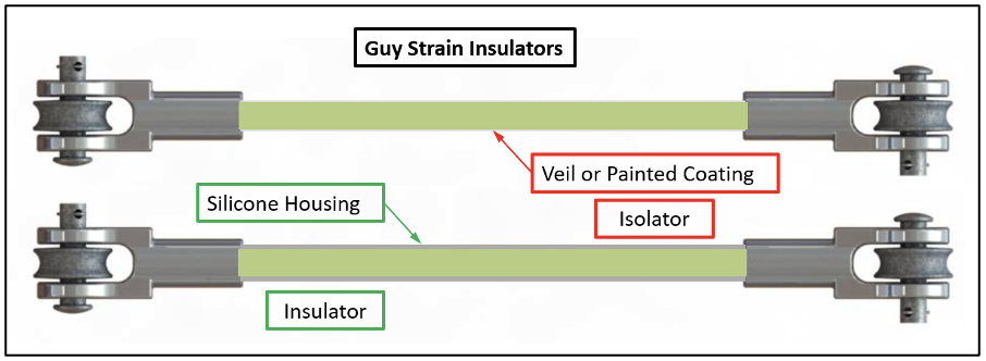
Comment:
An electrical grade core rod with a silicone housing is an ‘insulator’.
An electrical grade core rod without a silicone housing is an ‘isolator’.
Guys strains & brackets with painted or veiled rods do not have the insulating protection of a silicone-coated design.
End Fittings
The metal components attached to the ends of a polymer insulator are the end fittings. Depending on strength rating of the insulator (SML), these could be made of either ductile iron or steel. The higher the SML, the more likely an end fitting is a form of steel, whether cast or forged. Both iron and steel are then finished with a galvanized coating to protect the metal from harsh environments, which might otherwise cause corrosion and rusting.
 Like all other parts of a polymer insulator, not all end fittings are the same. Although the connection types of end fittings are common and mostly well defined in the standards, an end fitting barrel is fully defined by each supplier.
Connection Types [ANSI & IEC]
• Socket & Ball (Most defined set)
◊ ANSI 52-5 (30k), 52-8 (40k), 5-11 (50k)
◊ IEC 16 (120 kN), 20 (160 kN & 210 kN), 24 (300 kN), 28 (400 kN), 32 (500 kN)
• Y-Clevis / Ball (Most common in US)
• Oval Eye / Oval Eye
• Clevis / Tongue (Well defined set)
• Clevis / Clevis
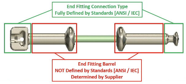
The connection ends of fittings are mostly governed by standards and gauges, but some are better defined and more complete then others. For example, the most defined set of end fittings would be the socket and ball connections, which whether ANSI or IEC are fully defined by Go & No/go gauges. Second to the socket and ball would be the Clevis / Tongue or Clevis / Clevis set of end fittings, which are also well defined but used primarily for international applications. At times, these can have non-standard SML ratings, defined by the customer in their specification.
Fact: In the U.S., the most common set of end fittings used are Y-Clevis / Ball for suspension and Oval Eye / Ball or Oval Eye / Oval Eye for Dead-end application.
While the connection type of end fittings is more common and defined by standards, their remaining connection geometry (sometime referred to as the barrel) is typically 100% unique to each individual insulator manufacturer.
Aside from connection geometry, end fittings can have many differences:
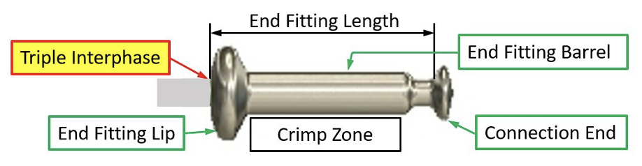
1. End Fitting Length: The length of each end fittings is determined by connection geometry and design of the end fitting barrel. It is likely that barrel geometry for each end fitting will be the same for each strength class. But when combined with different connection types, end fitting length varies for each type;
2. End Fitting Barrel: Length and outside diameter (OD) of the barrel of the end fitting are driven by the crimp zone as well as the crimping technology used by each manufacturer. Geometry of the crimp zone fluctuates based on amount of material displacement required to attain any desired SML rating.
3. Crimp Zone: Area along the length of the end fitting with manufacturing clearances at both ends to allow for proper compression of the end fitting;
4. End Fitting Lip: This is the end of the barrel opposite the connection end and this is where designs can vary most. Some can have very small radii at the ends while other designs can have a greater mass of metal making up the lip or corona ball.
• The need for the corona ball or larger lip is to prevent exposure of the core should an arc terminate on the end fitting. In the event of arc termination, the corona ball would be able to withstand multiple impulses without breaching the end fitting triple interphase;
• The larger lip is called a corona ball because it is designed to act as a small OD corona ring, providing protection from E-field stresses at the triple interphase;
• Finally, the corona ball feature can be the mounting geometry for a corona ring.
5. Triple Interphase (Point): This is the area where the rod, rubber and end fitting meet and in most designs is also the insulator’s sealing mechanism.
Fact: End fitting length most impacts insulator section length. The customer can match a length and make the dry arc distance variable or they can use the dry arc distance (rubber length) that would then make section length variable. Ideally, this is covered in the specification’s ± tolerance range.
End Fitting Procurement
As for pultrusion of the core rod, it is unlikely that casting, forging and galvanizing processes will take place in the same factory where insulators are being assembled. Rater, end fittings are typically sourced, depending on supplier and location. For example, most insulator manufacturers in the U.S. source all transmission class end fittings from countries such as China, India, Mexico and Brazil.
Fact: The manufacturer of a polymer insulator should do their own investigation and approval of each potential end fitting supplier as part of their internal quality system. It is unlikely that any supplier will ‘cut corners’ on quality of end fittings given how critical these are to performance of any polymer insulator design.
Evaluating Quality & Performance Pertaining to End Fittings
• The polymer supplier should be prepared to present customers with a complete evaluation and quality documentation for each approved end fitting sub-supplier;
• The supplier should present how they design and use their end fittings as part of the polymer insulator, including how end fitting design may or may not impact corona ring design and application;
• As with all materials, country of origin should be marked on end fittings;
• Each supplier should have a defined lot control process with the ability to track these lot codes to the production of the finished insulator;
• Each supplier should be able to provide documentation on how the end fittings are qualified, which can include ultimate strength ratings (which may also be part of the crimping process).
Conclusions
The process of evaluating polymer insulator designs can prove challenging, especially given the range of various material options. Users are well advised to use governing standards to assist in determining which designs best meet their needs. But the standards are sometimes not sufficient. Customer should also have a robust and detailed specification defining performance criteria and knowing which materials to require and what dimensions to make critical. Understanding the various options for a polymer insulator design and how these can impact long-term service performance is vital in order to conduct an effective evaluation of each supplier.
Appendix A: Multi-Axis Combined Loading & Load Curve Definitions
Appendix B: Brittle Fracture