Station posts insulators are typically more vulnerable to flashover under wet and contaminated conditions than other substation insulators, especially at higher voltages. Two alternatives have therefore commonly been used to improve contamination performance, i.e. adding more leakage by means of taller posts, ribbed shed designs or booster sheds or coating with hydrophobic materials such as RTV silicone.
This edited past contribution to INMR by Dr. Ravi Gorur employed 3-D electric field calculations to model comparative pollution performance of porcelain station post insulators in AC systems up to 1200 kV. Research revealed that for posts used in systems greater than 500 kV, coating the porcelain with RTV silicone or replacing them with composite designs offered superior protection against flashovers initiated under contaminated conditions. At lower voltages, increasing leakage and applying an RTV coating seemed equally effective.


Although apparatus insulators have been moving more and more to composite designs with silicone housings, porcelain remains the dominant insulator used for bus supports and switch columns. That means that these insulators must be able to withstand the typical pollution environment at stations. For example, cooling towers at nuclear and fossil fuel generating stations use steam turbines and the water is typically treated with chemicals to prevent algae growth and improve heat transfer properties. Conductivity of this treated water is relatively high and, whenever the cooling towers are not properly maintained, this treated water is liberated along with other vapors. Depending on wind conditions, insulators in the switchyard can become exposed to high conductivity water spray. Coal dust is another common contaminant.
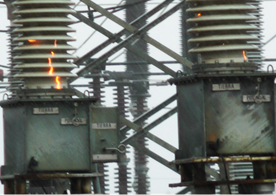
In the case of electrical apparatus such as transformers, circuit breakers and surge arresters, electric field is controlled by means of external corona rings or internal capacitive grading. These, however, are lacking in station posts, which are manufactured in several section lengths (usually from one to four units depending on voltage) with intermediate connections. With minimal hardware between these separate porcelain columns, voltage distribution is generally more non-linear than on an equivalent suspension string and the resulting electric field concentration can give rise to corona under dry conditions. Moreover, the small shed spacing (typically 5-8 cm) that can easily be bridged by water drops or arcs means that surface discharges under wet and contaminated conditions can quickly lead to flashover (see Fig. 2).
The key to improving contamination performance in such instances lies in minimizing leakage current. This is achieved by such measures as periodic cleaning or by increasing leakage distance using taller posts, ribbed or alternating diameter shed designs and even polymeric creepage extenders. Use of semi-conducting (or resistive) glazed porcelain is another way of combating pollution problems and relies on a combination of linear voltage distribution and heated surface to suppress discharge activity. While all these methods are successful to various degrees, replacing insulators with improved shed profiles or with resistive glazed insulators is neither practical nor economical if the station is already in operation. In such cases, improving contamination performance of the ceramic insulators is often achieved by coating them with hydrophobic materials such as greases or room temperature vulcanizing (RTV) silicone coatings. While these coatings can be applied under energized conditions, it is preferable and usually more effective to apply them under de-energized conditions. Moreover, whenever possible, this is better performed indoors rather than in the field.
Electric field at the arc root plays a critical role in the flashover process and arcing is more intensive toward the energized electrode. In combination with wet surfaces at this end, arcing and water droplets can bridge the sheds leading to flashover – even if the surface away from the energized end is not fully wetted. For inert materials such as porcelain, flashover voltage exhibits a linear relationship with leakage distance. However, since the relationship of electric field with arc current is nonlinear, a greater benefit can be achieved if the electric field at the arc roots is somehow subdued.
With the computing power available today, numerical electric field analysis can provide valuable insight into the performance of insulators and other such devices. This research project has used the Coulomb software package based on the Boundary Element Method (BEM) and whose simulation accuracy depends on the number, shape and distribution of boundary elements utilized. Fig. 3 shows triangular shaped boundary elements (selected since they yield better accuracy than other shapes) for modeling a post insulator under dry and wet conditions. For the dry case, the entire surface was divided into equally sized elements.
It was assumed that only the exposed top surface of the porcelain shed is wetted, while the protected undersurface remains dry. This assumption was based on experiments and field experience that demonstrate this combination of dry and wet surfaces represents the worst-case scenario for contamination compared with uniformly-wetted insulators. It was also assumed that the wetting pattern was axisymmetric, meaning that it would be sufficient to model only a segment of the surface. Larger numbers of elements were then used to simulate wet surfaces when compared to the dry case (typically 3 times more). The thickness of the water film on the top surface of the sheds was assumed to be 1 mm, seen as reasonable since in most outdoor locations a dust film covers the top surface.

Insulators Modeled
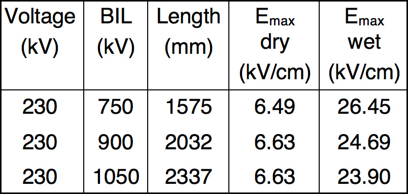
The dimensional details of the different post insulators were obtained from manufacturers catalogues as well as from input by electric utilities (see Table 1). Electric field was then calculated along the straight line connecting the tip of each shed. For multiple section station posts, as used at higher voltages, only the electric field along the top section was plotted since the field in the lower sections is comparatively small.
Electric Field Under Dry Conditions
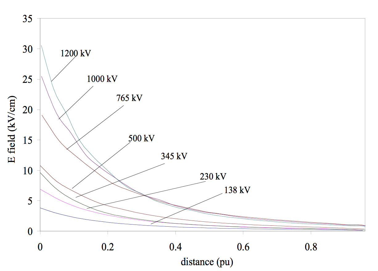
The electric field plots shown below are calculated along the line joining the tip of each shed. In these figures, the horizontal axis is stated in terms of per unit of dry arcing distance, starting from the line end. Fig. 4 shows the electric field variation under dry conditions for different voltages. A value of 15 kVrms/cm is considered as the usual threshold for corona initiation. It can be seen that for system voltages of 500 kV and less, the highest electric field is below this threshold value and therefore no special measures for corona mitigation are required. For transmission systems with voltages greater than 500 kV, however, it is essential to have a corona mitigation device such as a grading ring to minimize audible noise and RIF. While porcelain is generally immune to damage by corona, if composite insulators are used then corona suppression devices are needed in order to protect their housings from damage.
Electric Field Under Wet Conditions
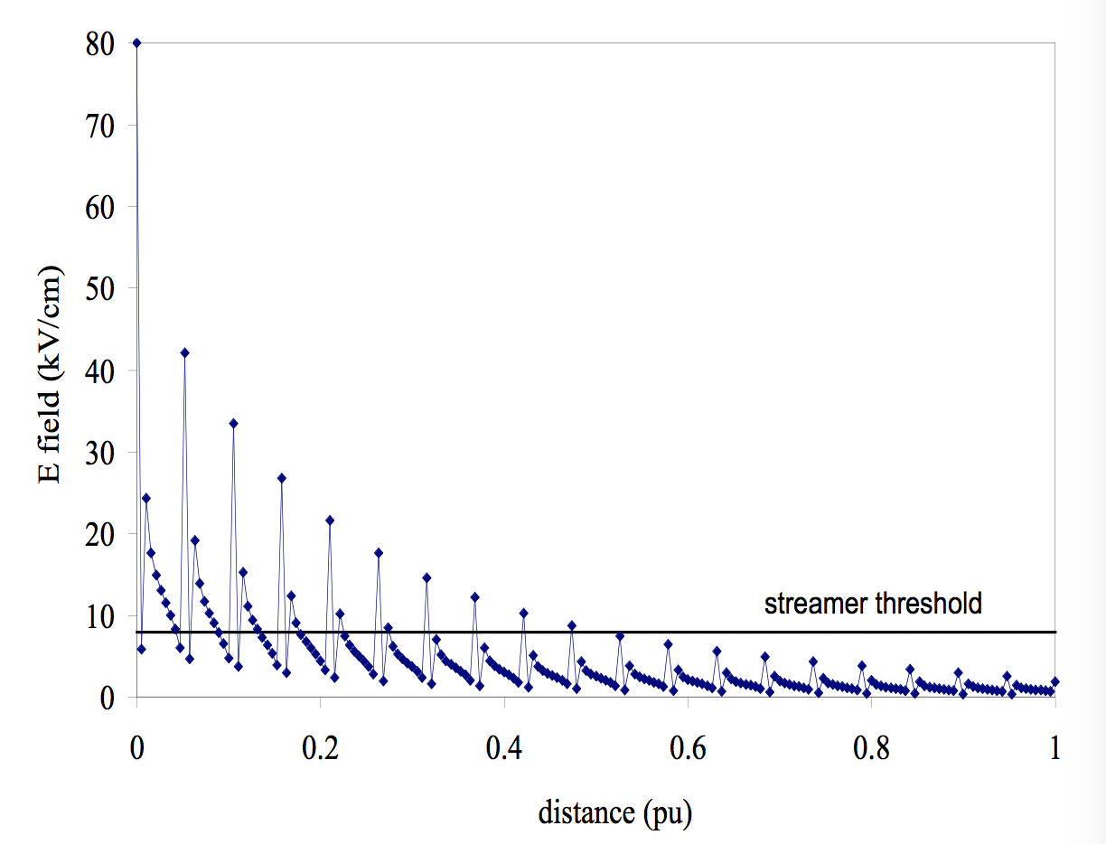
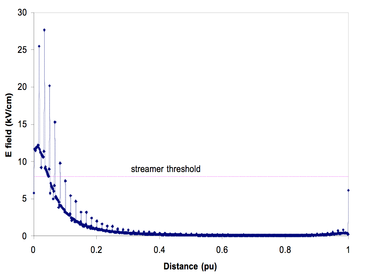
It is easier to wet the exposed top of an insulator than the protected undersurface. Hence the water film was considered to be on the upper side of each shed while the under portion was assumed to be dry. Water conductivity was varied from 20 to 4000 µS/cm – the lower value being typical of rain while the higher value corresponds to cooling tower intake. Electric field spikes at the triple point junctions of the water film, the porcelain and the surrounding air. The electric field necessary to initiate streamers is known to vary from 4.5 to 11 kV/cm, the lower value for positive polarity and the higher for negative polarity. A value of 8 kV/cm is considered as the threshold and is shown in all the figures.
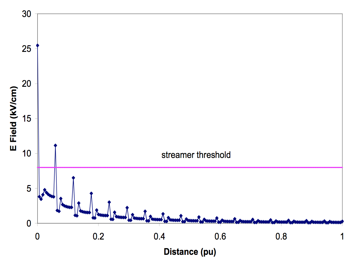
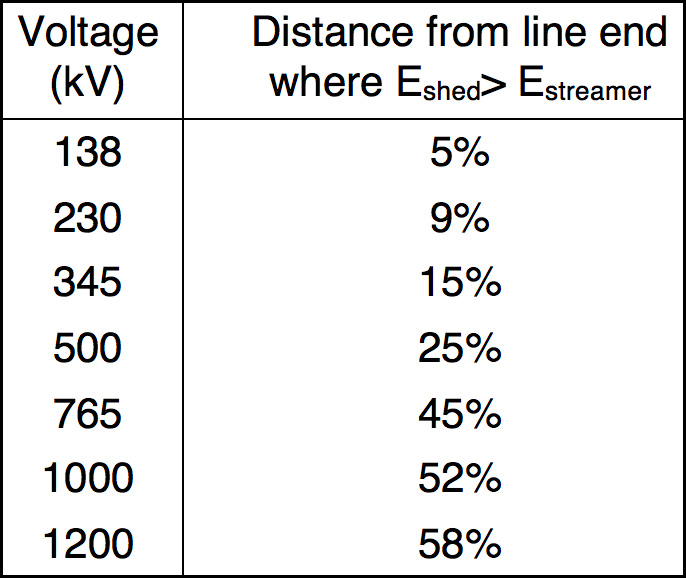
As can be seen from Figs. 5 and 6, electric field enhancement increases with system voltage. Also, the region where the electric field is higher than the streamer threshold extends further from the line end electrode as the system voltage becomes greater. This is indicated in Table 2 which shows that discharges can readily occur and propagate during wet conditions. Whether or not they lead to flashover then depends on the resistance of the unbridged portion of the insulator that is in series with the arc. One sure way of preventing contamination flashover is therefore to ensure that the region near the energized electrode (where the electric field exceeds the streamer threshold) is made as small as possible.

Comparison of Alternative Flashover Mitigation Methods
a. Using Taller Posts
Basic Impulse Insulation Level (BIL) for the same system voltages can vary among utilities. Table 3 lists three different lengths of 230 kV rated station posts for different BIL. It can be seen that increasing the dry arcing distance (or height) has only a minimal impact on lowering the average electric field. Therefore, to achieve a meaningful reduction in electric field, the height of an insulator needs to be increased by a much higher value. Using taller posts then raises issues with regard to insulation coordination and extra costs are incurred to accommodate the increased height of buses. For this reason, other methods of improving contamination performance are preferred.
b. Using Different Shed Profiles
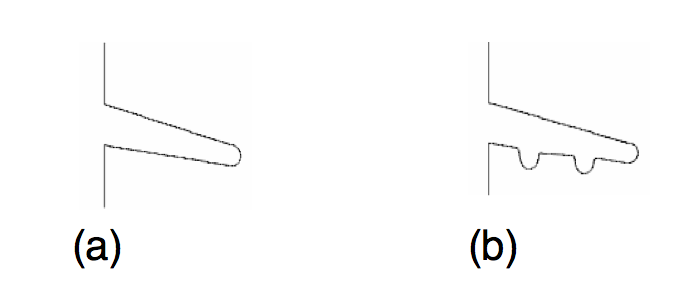
Insulator posts with under ribs that provide increased leakage were evaluated and compared to a profile without such under ribs (Fig. 7). The additional leakage distance gained compared to the standard units is about 10%.
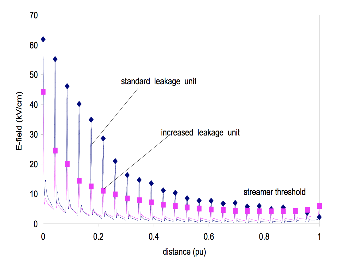
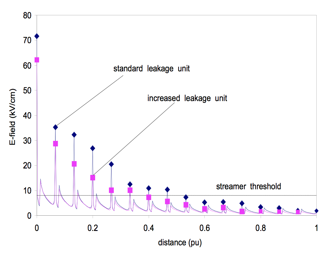
The electric field for 138 kV post insulators is shown in Fig. 8. It can be seen that the increased leakage distance units provide significant reduction in electric field concentration compared to the standard leakage insulator. Also, they reduce the region where the electric field exceeds the streamer threshold from 65% to 40% of the distance from the energized end. Fig. 9 shows these same results for 500 kV insulators. It can be seen that when compared to the 138 kV rated units, the standard and the increased leakage units show smaller reductions in both electric field concentration and in the region from the line end where electric field exceeds streamer threshold. As such, one can conclude that for EHV and UHV system voltages, increasing leakage distance alone may not be sufficient to achieve the desired improvement in contamination performance.
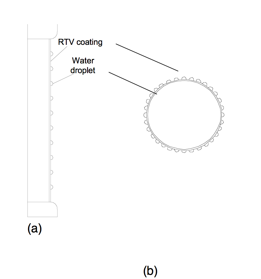
c. Using Hydrophobic Coatings or Silicone Insulators
The surface of inherently wettable porcelain can be made hydrophobic by application of materials such as greases or room temperature vulcanized (RTV) silicone rubber coatings. Water beads up on such surfaces giving rise to very high resistance under wet conditions compared to an uncoated surface and this helps to minimize or even eliminate leakage current. The specimen insulator was modeled as a cylindrical rod (Fig 10) with a height equal to the dry arcing distance and a diameter equal to the average of the shed and shank diameters. The thickness of the coating used was 0.5 mm (20 mils), a value typically recommended by coating manufacturers. Each water droplet required 20 boundary elements and there were a total of 36 water droplets evenly distributed along the circumference. The number and distribution of water droplets was sufficient to illustrate the important role of hydrophobicity and to evaluate its impact on electric field distribution at the surface.
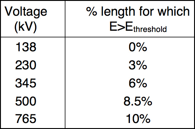
The plot of the electric field distribution for 765 kV insulators is shown in Fig. 11. It can be seen that the electric field exceeds the streamer threshold for 10% of the total length of the insulator. The percentage length for which electric field exceeds streamer threshold was calculated for insulators at other rated voltages and is shown in Table 4. It can be seen that this critical value is much lower in the case of insulators coated with hydrophobic materials than for uncoated insulators (compare with Table 3). Therefore, although sheds near the high voltage end can be bridged by water drops or arcs, the arc does not lengthen enough to cause flashover.

Based on these findings, it seems clear that coating EHV and UHV station posts in contaminated areas with hydrophobic materials provides superior improvement in performance compared to other methods. Of course, as the coating ages wetting pattern can be expected to change and with it surface electric field distribution. The STRI classification method is a fairly good indicator of such changes over time. In the worst-case scenario, once the entire coated surface is completely wettable, it would behave basically the same as uncoated porcelain and there would be a need for re-coating. But, if a coating is properly applied, it should provide improved performance for many years. Moreover, if silicone-housed composite insulators are specified for such applications (assuming they can handle the mechanical requirements), they would provide superior contamination performance by virtue of their inherently long-term hydrophobicity.
An important observation obtained by comparing Figs. 6 and 11 for insulators with wettable and hydrophobic surfaces is that the electric field in the latter case is significantly reduced. An immediate benefit therefore is that during humid or wet conditions, corona and related nuisances such as audible noise, radio & television interference and ozone production should be significantly reduced compared with conventional porcelain insulators. Composite insulators which are now available up to 1000 kV can also be especially attractive for station apparatus, especially at higher voltages, due to their non-brittle nature and relatively safe failure modes.