Along with China’s rapid economic growth over the past three decades has come a major revamping of that country’s energy and load planning strategies. In particular, DC transmission has begun to take on an increasingly important role since 1990 due to its known advantages for HV & UHV lines running great distances.
Starting with the ±500 kV of Ge-Nan project, first commissioned in 1989, and the ±800 kV Xiang-Shang and Chu-Sui lines completed in 2010, the framework of a huge DC backbone has now taken shape across the country. Indeed, by the end of 2012 China was already operating three ±800 kV lines, one ±660 kV line, ten ±500 kV lines, one ±400 kV line as well as three back-to back DC connection projects. More DC lines are in planning, under construction or recently commissioned.
During development of these various DC projects, there has been considerable experience with failures of external insulation on certain apparatus. At the beginning, there were a relatively large number of such faults. But after applying suitable countermeasures, these have progressively been reduced to the current situation of mostly trouble-free operation.
This past article, contributed by experts at the Electric Power Research Institute in Beijing, reviewed research conducted by the State Grid and the China Southern Grid on external insulation faults at ±500 kV converter stations, using voltage dividers as the reference for experience with a range of equipment.

Overview of ±500 kV Point-to-Point DC Transmission in China
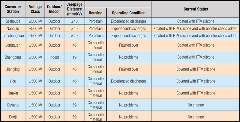
At the start of 2012, China already had a total of 10 operating ±500 kV point-to-point DC systems with a combined transmission capacity of some 28,800 MW (see Table 1).
Ge-Nan, China’s first long-distance DC transmission line, ran from the Gezhouba Station in Hubei to Nanqiao in Shanghai and its equipment and design came entirely from suppliers based in Europe. About 2009 to 2010, this initial system was retired as part of a comprehensive retrofit lasting some 6 months and during which capacity was increased to 5.786 billion kWh.
The Jiang-Cheng, Long-Zheng and Yi-Hua DC lines, transporting up to 9000 MW from the Three Gorges to Guangdong and Huadong, were designed jointly by Chinese and western-based suppliers. During 2010, the availability of these systems was high (respectively 17.23, 13.89 and 14.91 billion kWh) and together they accounted for 55% of the total capacity generated at that time at the Three Gorges.
Similarly, China Southern Power Grid’s Tian-Guang, Gao-Zhao and Xing-An DC transmission systems were designed jointly by Chinese and German suppliers and had a combined capacity of close to 7800 MW. By early 2010, the Tian-Guang system’s transmission capacity was up to 5 billion kWh while those of the Gao-Zhao and Xing-An lines were 12.25 and 13.38 billion kWh respectively.
The ±500 kV De-Bao, Yi-Mu and Lin-Feng DC systems, commissioned after 2010, were entirely designed in China and, aside from certain key technologies and equipment, everything was locally produced. Up to now, these lines have had mostly stable operation, apart from individual discharge faults on the line side flat wave reactor, found to be due to a design defect.

External Insulation Faults Affecting ±500 kV DC Voltage Dividers
Faults at JiangLing, LongQuan & YiDu Converter Stations
Flashovers of external insulation on ±500 kV DC voltage dividers at Jiangling, Yidu and Longquan Converter Stations were reported late in 2004, early 2009 and early 2010. These flashovers occurred under similar conditions of more than 2 weeks of persistent rain, including 2 to 3 days of heavy fog during which visibility was reduced to only about 5 m.
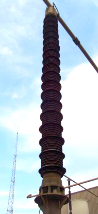
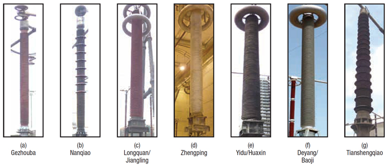
Suppliers of the affected equipment were contacted and confirmed that the same silicone rubber material was used on all bushings of the affected DC voltage dividers. Table 2 lists the technical parameters of these units, which are shown in Fig. 1.
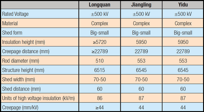
Housings on the DC voltage dividers at Longquan, Jiangling and Yidu were all silicone rubber type with basically the same section size. The grading rings on the equipment at Jiangling and Longquan stations were also the same although the voltage divider at Yidu had a different single ring structure. In 2009/2010, staff at the State Grid decided to apply RTV coatings to the composite housings of all three and there have been no further reports of problems since then.
Fault at Tianshengqiao Converter Station
In May 2005, again during a period of heavy rain, a flashover occurred on the porcelain housing of the voltage divider on Pole I at Tianshengqiao and white traces remained visible afterwards on the high voltage portion of the equipment. To prevent a recurrence, operating staff at the station decided to add booster sheds to the porcelain and also applied an RTV silicone coating (see Fig. 2). There have been no further flashover incidents with this apparatus.

Different External Insulation for Main ±500 kV DC Voltage Dividers
The housings of the voltage dividers used in the Ge-Nan and Tian-Guang DC projects were made from porcelain with relatively low specific creepage distance. However, once coated with RTV, I saw creepage distance as equivalent to that of a composite housed voltage divider. Moreover, at the Tianshengqiao and Nanqiao Converter Stations, the creepage distance of porcelain-housed voltage dividers, once coated with RTV and with added booster sheds, exceeded that of composite-housed units.
In addition, the design of the DC field busbar voltage dividers used on the Yi-Hua and De-Bao systems has been improved by reducing the size of their grading rings at the high voltage end. This permits more efficient use of the composite housing’s creepage. The external insulation on these different types of ±500 kV DC voltage dividers is described in Table 3 and shown in Fig. 3.

Failure Countermeasures
After analyzing past insulation faults affecting ±500 kV DC voltage dividers in China, the causes of these various problems could be grouped into the following categories:
a. Failures Due to Insufficient Creepage
The minimum specific creepage of equipment used on early ±500 kV DC projects in China (e.g. Ge-Nan and Tian-Guang) was only about 40 to 41 mm/kV. However, this value proved insufficient and indeed almost all equipment used in the DC field, including voltage dividers, experienced varying degrees of discharge phenomena – some even when operating at lower voltages. External insulation failures caused by lack of sufficient creepage were found best resolved by adding booster sheds or applying RTV coatings to increase external insulation strength.
b. Failures Due to Decline in Hydrophobicity
Flashovers of external insulation on ±500 kV DC voltage dividers at Jiangling, Longquan and Yidu Converter Stations under persistent rain and fog were traced mainly to decline in the hydrophobicity of their composite housings and resulting diminished performance under conditions of high pollution and wetting.
While water dripping from the sheds of a saturated insulator due to gravity takes some deposited surface salts with it (effectively cleaning the surface), a decrease in hydrophobicity means that a continuous film of conductive moisture can more easily form on the surface of polluted insulators. The result is a serious net reduction in dielectric strength. Indeed, research has demonstrated that hydrophobicity has such a significant influence that the pollution flashover voltage of composite insulators under good hydrophobicity is 2.4 times higher per unit length than when this property has been lost. For example, under pollution conditions of ESDD = 0.10 mg/cm2 and NSDD = 0.60 mg/cm2, pollution withstand of composite insulators whose surface hydrophobicity is lost is approximately 47 mm/kV.
In 2009/2010, ESDD levels on post insulators at the Longquan Converter Station reached 0.08 mg/cm2 and in the case of the Yidu Conveter Station were between 0.11 and 0.13 mg/ cm2. Given the 22,789 mm total creepage of the three DC dividers, their pollution withstand voltage under moderate contamination was only about 485 kV – less than the normal operating voltage. The probability of flashover became high simply because there was no longer any insulation margin.

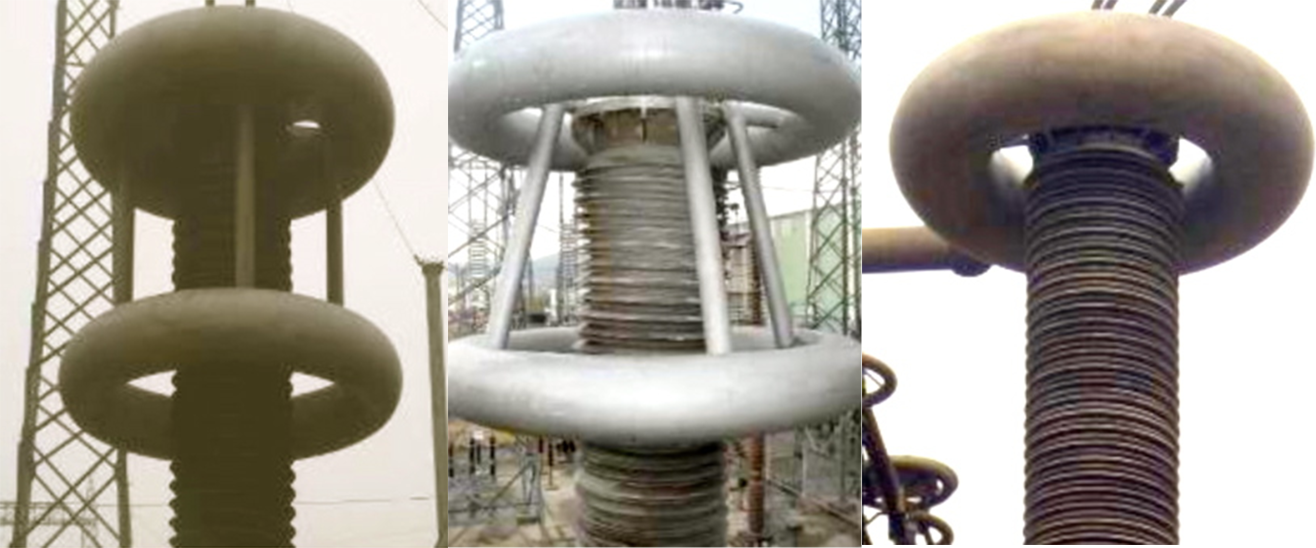
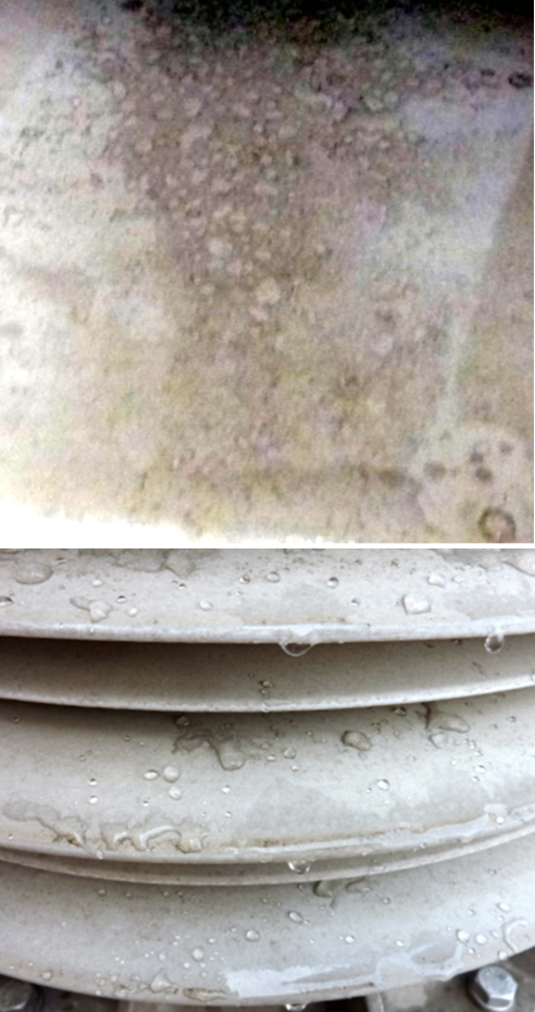
PTs used in the Long-Zheng, Jiang- Cheng and Yi-Hua DC projects were all supplied by a European-based multinational and investigation at Huaxin and Yidu converter stations revealed that even unused spares from this manufacturer had poor hydrophobicity on shed surfaces, i.e. only HC5 to HC6. Figure 4 shows examples of the hydrophobicity of these standby indoor DC voltage dividers.
Composite insulators with diminished surface hydrophobicity are more likely to experience arc burns as well as tracking and erosion caused by partial discharges or corona activity under service conditions marked by UV, temperature change, rain, fog, snow, etc. Loss of hydrophobicity by a composite insulator usually means unsatisfactory service performance since, even if it does not experience pollution flashover or serious discharge phenomena, it will still require greater scrutiny by maintenance staff.
Moreover, premature ageing of silicone rubber sheds and housings due to a variety of service stresses might cause performance to decrease as the insulator mcould experience discoloration, loss of gloss, hardening, deformation, cracking or increased brittleness.
In such cases, one solution would be to coat the unit with RTV material to restore hydrophobicity and increase pollution flashover voltage. At the same time, this experience has shown that it is a good idea to regularly monitor silicone insulators – even on spare equipment – for any possible decrease in hydrophobicity.
c. Problems Due to Design Defects
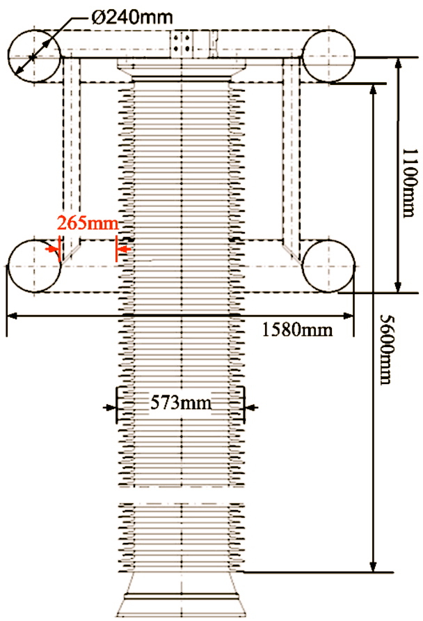
Another cause of flashovers on ±500 kV voltage dividers at Jiangling and Longquan Converter Stations under conditions of fog or drizzle was discovered to be poorly designed grading rings and insulator sheds. The external insulation distance of the DC voltage dividers at the two affected stations was 5600 mm.
Their circular grading ring at the high voltage end had a diameter of 1580 mm while tube diameter was 240 mm. Given the grading ring’s shield depth of about 1100 mm, the air gap between it and the nearest bushing shed was only about 265 mm – clearly too short.
Basically, because some grading rings have such high shield depth, effective creepage distance of composite bushings can be shortened by as much as 20%. When the surface becomes wetted, the air gap between the grading ring and the nearest shed on the bushing has to withstand very high voltage, especially when the temperature near the top of the divider (i.e. within range of the grading ring) is relatively high. Once the air gap breaks down, all voltage is taken on by the lower portion of the insulation and voltage per unit of creepage for this section increases by 20% relative to that along the whole bushing. This can induce flashover.
In addition, spiral-shaped voltage divider housings with big-small alternating shed configurations do not seem ideal when it comes to inhibiting rapid increases in surface leakage currents. This is because, should hydrophobicity be reduced or lost, water on the sheds can more easily flow down along the spiral surface and accelerate formation of a full film of moisture.
The geometry of the composite bushings on faulted voltage dividers was basically the same as that of the porcelain bushings used on DC voltage dividers at the Gezhouba Station that never flashed over (even though they did experience minor discharge phenomena on their surface). The explanation here may be that while the composite housing has alternating sheds with spiral structure, the alternating big-small sheds on the porcelain bushing are concentric.
By contrast, the reason that the porcelain-housed DC voltage divider at the Tianshenqiao Station experienced flashover during rain was that the geometry of its sheds was poorly designed. In this case, the spacing between the large sheds was 65 mm while width of sheds was 65 mm to 70 mm, meaning a ratio of close to 1. Moreover, the difference in the widths of the small and big sheds was just 20 mm. A DC arc is more stable than an AC arc and therefore any arc-shortening phenomenon between sheds becomes more serious since it reduces effective utilization of the entire creepage.
It has been found that the pollution and rain flashover performance of any DC device that has relatively small shed separation distances on its external insulation can be improved by installing silicone rubber booster sheds. These not only control shorting of adjacent sheds by an arc but also improve the condition of the insulation when wetted. Utilization rate of the creepage distance is improved as well.
Classification of Alternative Flashover Countermeasures
China’s Electric Power Research Institute analyzed localized arc generation and its impact on various configurations and types of external insulation on DC devices experiencing different forms of discharge (i.e. severe, moderate and slight).
The goal was to facilitate evaluation of discharge phenomena under various wetting conditions such as fog, rain, snow and ice as well as to judge the comparative reliability of different insulation based on field and laboratory experience. At the same time, this analysis would assist classifying the most appropriate countermeasures to deal with discharges in each case (see Table 4).
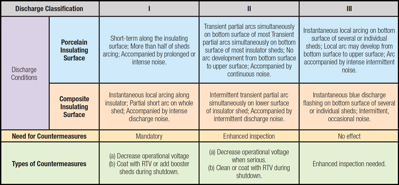
Based on the existing operating situation at each converter station studied, discharges in the DC field during fog or rainy weather were either partial arcs along the surface of the external insulation or corona discharges at the insulator fittings. Different countermeasures are appropriate to deal with such problems. For example, equipment should be taken out of service and either coated with RTV silicone or have booster sheds added if experiencing level II or level III discharges. Moreover, if there are corona discharges, better grading should be installed to improve field distribution and reduce or eliminate such phenomena.
At the same time, there should be greater monitoring of silicone composite bushings as well as of the hydrophobicity on the surface of RTV coatings at a converter station. In particular, it is important to inspect for any sustained loss of hydrophobicity during several days of consecutive humid conditions as well as the rate of hydrophobicity recovery once the weather improves. It is also recommended to test for hydrophobicity changes due to the existing surface pollution layer and prevailing weather conditions, with measurements best carried out when there are several days of continuous sun. The ideal interval between recoating with RTV silicone should be determined according to the station’s specific operating environment. The surface of composite external insulation does not normally need to be cleaned or washed since this can result in short-term damage to the hydrophobicity of the silicone rubber material. The only exception is when the pollution layer has become so thick that the low molecular weight species in the bulk rubber that are responsible for transfer of hydrophobicity can no longer effectively migrate to the surface.

Summary
At the end of 2012, China had already built ten ±500 kV point-to- point DC transmission circuits, transporting a total capacity of 28,800MW. These ±500 kV transmission lines have now taken on an important role in interconnecting the country’s regional power grids.
Typical external insulation failures of DC dividers at ±500 kV converter stations include flashover of both composite and porcelain bushings, typically occurring under severe wet weather such as fog, sleet or heavy rain. The main causes of failures on potential transformers have been found to be inadequate external insulation configuration, reduction or loss of surface hydrophobicity of the composite housing and design defects in the equipment.
The main measures to improve the level of external insulation in such cases have been found to include adding a coating of RTV silicone to the porcelain or to the composite insulators as well as installing booster sheds. Periodic monitoring of surface hydrophobicity of the silicone housing or of the RTV coating should also be increased. Problems due to inappropriate grading ring design and/or shed geometry should be identified and solved as quickly as possible.
Discharges affecting equipment in the DC field of converter stations can fall into one of three classifications: severe, moderate or slight, and different measures are required to deal with each. Ideally, equipment should be coated with RTV material or have booster sheds added should either level II or level III discharges be present.