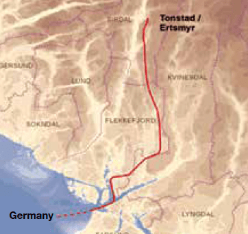
Statnett, the Norwegian TSO, has recently been in the process of network expansion along its Western Corridor – the transmission grid in the country’s southwest. This multi-billion dollar project has spanned several years and has been completed in stages, referred to as ‘Packages’. Package 1, for example, saw existing lines re-routed or dismantled and also construction of an entirely new 420 kV triplex line as well as a new HVDC line. The project was intended to ensure sufficient transmission capacity to serve southern Norway during any outages needed in repair situations or in regular operation and so that the expected 10 TWh growth in supply of hydroelectric power can be connected to the grid. It was also aimed at assuring enough transmission capacity for realization of one interconnection to Germany (NorNed) and one to the U.K. (NSL). The latter, at 720 km, will become the world’s longest subsea cable. As such, the rapid growth in the region’s network was propelled by Statnett’s strategy of assuring the grid capacity for connection of new renewable power and planned cable interconnections.
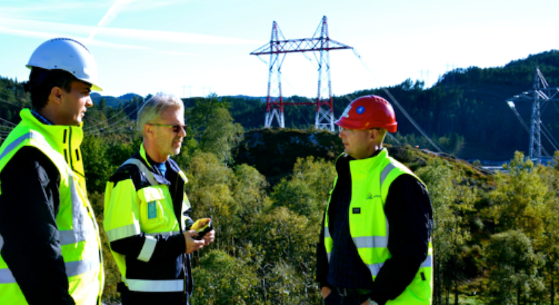
All this work was done against the backdrop of the country’s challenging climate and topography as well as a long coastline that exposes some lines to winds carrying contamination inland. These factors influenced insulation and line design. Yet another constraint was doing whatever necessary to secure public acceptance of lines that pass near sensitive areas such communities, nature trails and animal migration routes. INMR visited construction sites in September 2016 and met Statnett engineers as well as staff at the Croatian contractor awarded the turnkey contract for Package 1.
Transmission line design in Norway is influenced greatly by considerations of icing given the severe Nordic climate. Lines are designed on a span-by-span basis with ice loads ranging from 4 to 25 kg per meter of conductor. A second important design factor is galloping and or turbulent winds. Long spans crossing valleys or fjords can be particularly vulnerable and most exposed line sections are therefore designed for Category 2 hurricanes. Several solutions can be employed, such as, tension towers with larger phase spacing, increased tension in earth wires and interphase spacers.
[inline_ad_1]
Pollution is yet another key design criterion and that means applicable ESDD levels are usually measured and assessed for all strategic new lines. Perhaps the most notable recent example where pollution was regarded as critical to future performance is the new ±525 kV line that will transport renewable energy through an undersea cable link with Germany.
CLICK TO ENLARGE
CLICK TO ENLARGE
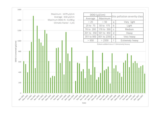
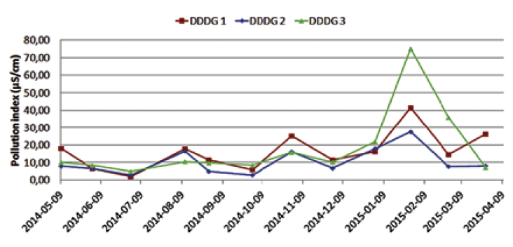
Over 50 km of this link is an overhead HVDC line that passes through the Western Corridor. To assess this new line’s exposure to salt carried inland from the sea during storms with strong winds (i.e. the dominant local element governing pollution), Statnett co-operated with researchers at STRI to set up directional dust deposit gauges (DDDGs) at selected sites. A DDDG collects airborne contaminants in cylindrical containers positioned to face all directions. Conductivity of the pollution deposited into each container is then measured at regular intervals and converted into an applicable pollution index as well as an equivalent salt deposit density (ESDD) value. Comparing this with what is shown in IEC 60815 helps engineers dimension insulation to meet the pollution severity of the area. In this particular case, since the standard still applies only to AC, conversion into DC was necessary. DDDG locations must of course be based on their being as representative as possible of the pollution that will impact a particular line or substation. If sited improperly, readings may not correlate well with what actually deposits on insulators nearby.
CLICK TO ENLARGE
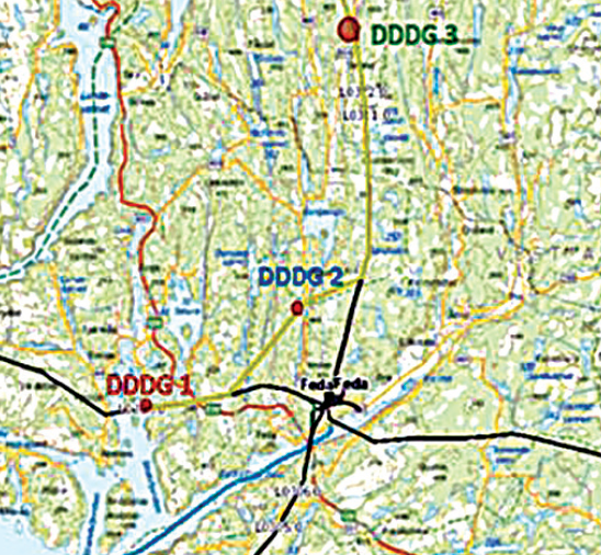
In the case of the planned new ±525 kV line, one DDDG was installed near to where the subsea cable portion comes ashore while another was placed about 10 km inland. A third was installed 25 km in from the planned cable transition point. Normally, one would expect the highest pollution level to be recorded by the unit placed at the coast where the undersea cable will transition to the overhead line. The other two DDDGs would then indicate how rapidly pollution declines with increasing distance from the sea.
CLICK TO ENLARGE
However, much to the surprise of researchers, the DDDG placed furthest inland ended up recording the highest pollution. A paper presented by Statnett during the 2016 General Session of CIGRE explained this anomaly by noting that the terrain where these measuring devices had been placed and their relative heights ended up influencing pollution readings. For example, the dense forest adjoining the cable transition site was thought to have shielded the DDDG in such a way as to significantly influence its ‘pollution capture’ during events such as storms from the sea. Similarly, the device further inland was sited on a hillside, also with surrounding tree cover. By contrast, the DDDG sited most inland was placed on a hilltop devoid of trees and therefore with maximum exposure to wind borne pollution. This experience confirmed how important it is to select truly representative sites for each DDDG to avoid risk of underestimating pollution.
CLICK TO ENLARGE
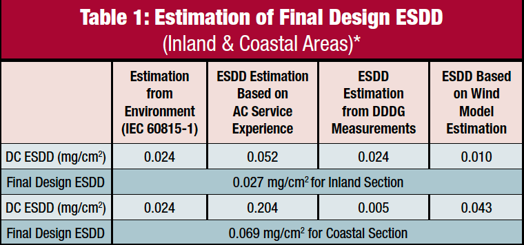
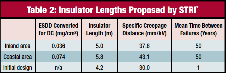
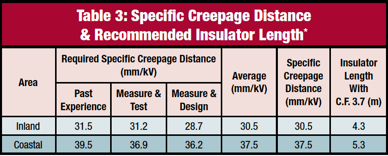
In the end, Statnett engineers based insulation design for the HVDC line on several factors, including the recommendations from IEC 60815-1 given the level of ESDD, past service experience with other lines in the area, pollution index based on the DDDG measurements and modeling of past wind and precipitation patterns. Table 1 summarizes expected impact of measured ESDD (after conversion for DC using a conservative multiple of 1.2) as well as insulator length and specific creepage distance on line performance defined in terms of mean time between failures.
CLICK TO ENLARGE
CLICK TO ENLARGE
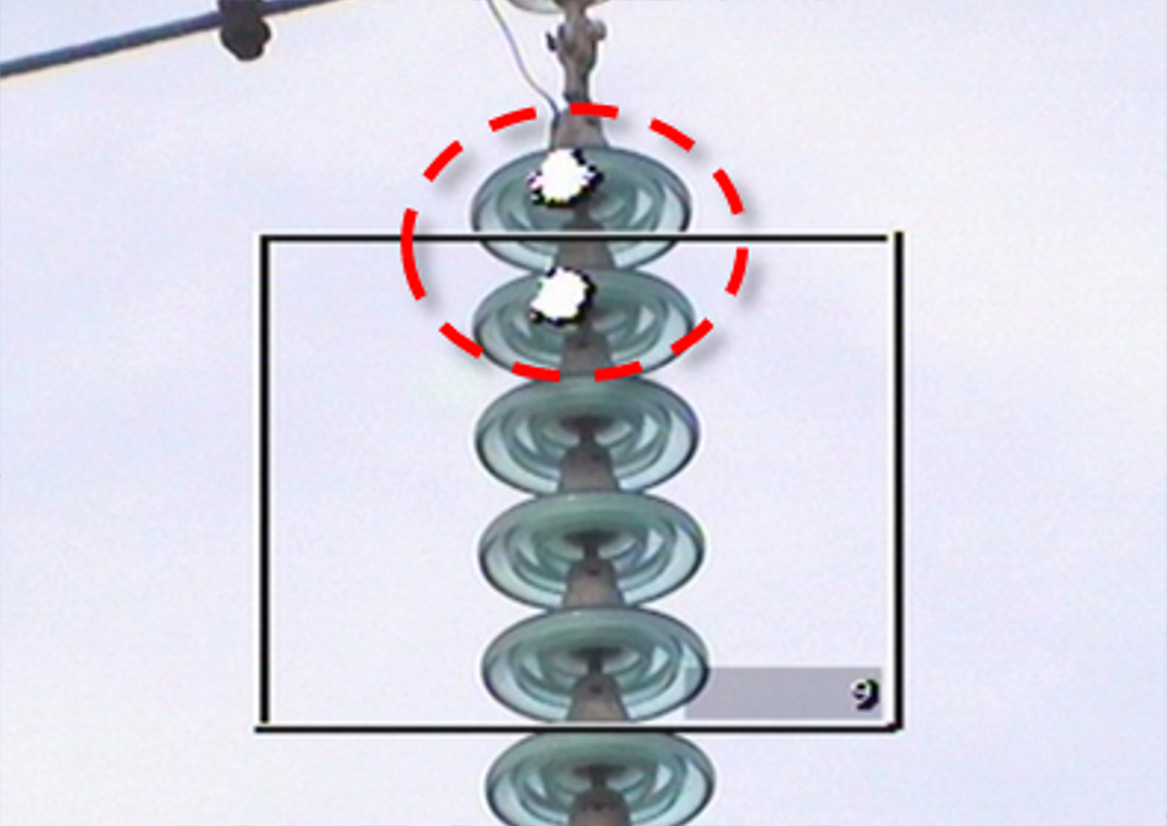
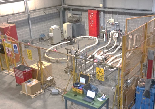
Originally, it was planned to use two different insulator lengths, one for the area located less than 10 km from the seacoast and one for the line section further inland. A more conservative philosophy was later adopted and a 5.3 m long insulator was initially chosen for the entire line. However, based on full-scale icing and pollution tests at STRI, insulator length was increased to 5.8 m (i.e. connection length 6.2 m). Apart from providing extra margin for unknowns related to the limited numbers of DDDG measurements, standardizing on one insulator string allowed for economies in purchasing, testing and handling. Pollution and icing tests were then carried out to verify design criteria.
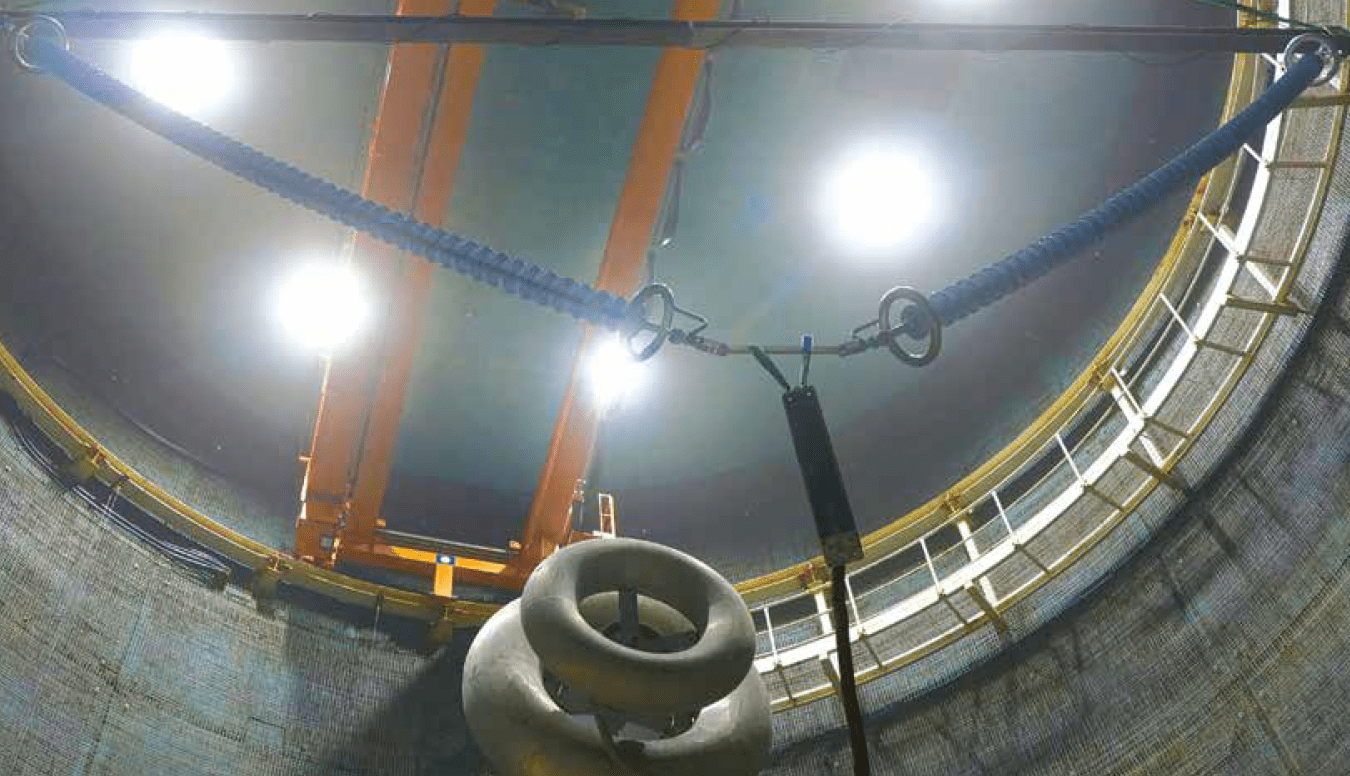
(photo courtesy STRI)
CLICK TO ENLARGE
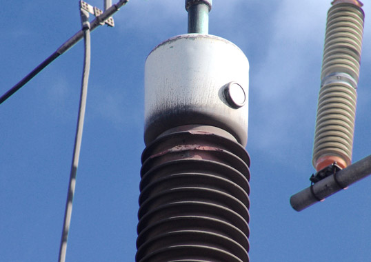
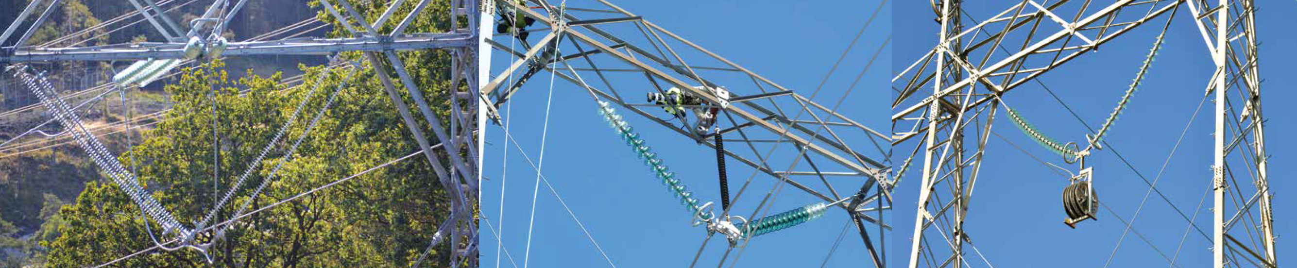
Glass has traditionally been the insulator of choice for overhead lines in Norway and is still favored since it has performed well and is easy to inspect – an important consideration in a country where lines are often difficult to access for maintenance.
CLICK TO ENLARGE
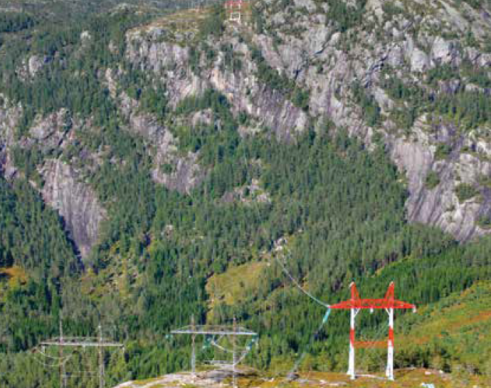
Still, in the end only composite insulators were selected for the new ± 525 kV line. According to engineers, superior pollution behavior made them the better choice both from an economic and a design perspective. Another important consideration that impacted design of the new ±525 kV line is corona, particularly since the highest system voltage in Norway up to now has been 420 kV AC (i.e. 342 kV peak line-to-ground). Moreover, since corona in DC is more critical than in AC, which is driven mostly by ambient moisture, noise level for the new line was designed to be half the typical noise of an AC line, i.e. about 40 dB. While the area surrounding the new line is not populated, Statnett engineers reported that there was concern for people walking the hills nearby.
[inline_ad_2]
All insulator assemblies and fittings for the ±525 kV line were specially developed in cooperation with the manufacturer and one of the main differences compared to standard 420 kV fittings is greater surface area and radius of curvature. Together, these factors contribute to reduced voltage gradients. Moreover, suspension and tension strings are outfitted with a corona ring designed to achieve favorable electric field distribution around fittings. Corona tests were performed at an independent laboratory on all types of tension and suspension strings as well as on accessories such as clamps and spacers, according to IEC 61284, which describes corona testing for AC up to 765 kV. In order to adapt to DC, peak voltages were calculated.
CLICK TO ENLARGE
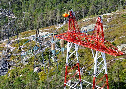
Optimizing insulator installation as well as tower construction techniques have been other high priorities to Statnett engineers involved in the Western Corridor Project – the former to reduce risk of possible handling damage to insulators that are over 6 m in length, the latter to maximize worker safety and productivity.
CLICK TO ENLARGE
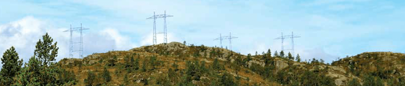
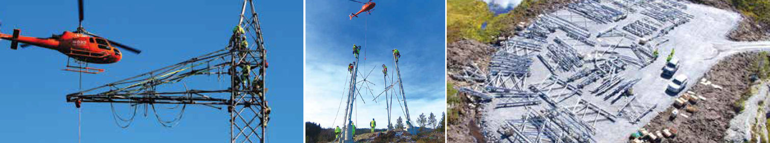
The new overhead lines traverse mountains up to 600 m above sea level with valleys that drop as much as 400 m and the longest single crossing is 1300 m. Ground conditions are mainly rocky with little top soil and sections of line route are accessible only by helicopter. Indeed, helicopters played a crucial role in constructing both the new triplex 420 kV line and the ±525 kV HVDC line. Tower elements pre-assembled at special sites and weighing up to 1200 kg were airlifted to tower locations.
CLICK TO ENLARGE
The tower selected for the new HVDC line was the second new tower type since the beginning of the 1980s. In 2012, Statnett developed an AC tower using circular hollow section (CHS) profiles and this same concept was applied for the new DC tower by removing one of the cross-arms and extending the remaining ones. Selected because it offers high strength in relation to weight, tower sections were supplied with pre-loaded bolts whose tightening procedure followed a pre-determined sequence. The structures stand up to 50 m and on average weigh 23 tonnes for tension towers and 14 tonnes for suspension towers.
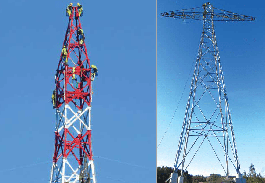
differences in leg lengths of as much as 5 m.
Bolt tightening followed predetermined sequence.
CLICK TO ENLARGE
According to engineers, the new line offered an opportunity to assess whether towers based on CHS profiles could yield reduced overall weight versus the steel angle profiles used for transmission towers in the past. Indeed, the profile finally selected to develop the line’s suspension and tension towers proved up to 10% lighter. In addition, apart from meeting the existing structure requirement of a difference in leg lengths of as much as 5 m to cope with steep terrain, these towers were also equipped with a special rail system on each leg. This ensured safe climbing while additional rails placed under flange joints allowed workers to be secured during fitting of sections and bolt tightening.
[inline_ad_3]
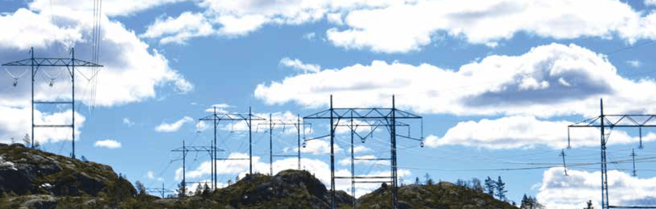
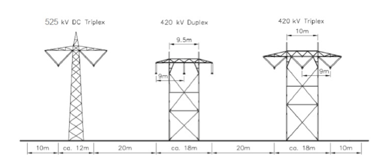
Apart from the new ±525 kV line, other key elements of Package 1 of the Western Corridor Project included a new 420 kV triplex line as well as dismantling or re-routing other lines around Feda Substation and the new Ertsmyra Converter Station. The simplex line that was dismantled was replaced by the new HVDC line that took over its section of the corridor but shifted an additional 10 m away from the existing center line. At the same time, the existing twin bundle line was upgraded from 300 kV to 420 kV. This process ended up allowing a separation of 20 m between the phase and pole of the new HVDC line and the line that was upgraded.
[inline_ad_4]
Statnett engineers explained that people more easily perceive a hybrid AC and DC field and measures therefore had to be taken to reduce the DC field to a lower value than if the line had been in a separate corridor. The primary means of field reduction is increasing tower or conductor height. To ensure minimal corona noise, all key line components – from insulators to clamps to fittings – were checked carefully after installation to ensure they were of the proper shape and that they had been correctly installed.
CLICK TO ENLARGE
Another of the major elements at this stage of the project was establishing a loop support structure bypass that helped reduce the total time for constructing the HVDC line as well as de-commissioning older line sections. The need for such a bypass was to keep existing lines in normal operation for as long as possible due to capacity challenges in the region and in the nearby city of Stavanger. So important was the goal of maintaining load security throughout, that teams of workers were standing by to quickly re-connect re-routed lines and deal with any unexpected problems.
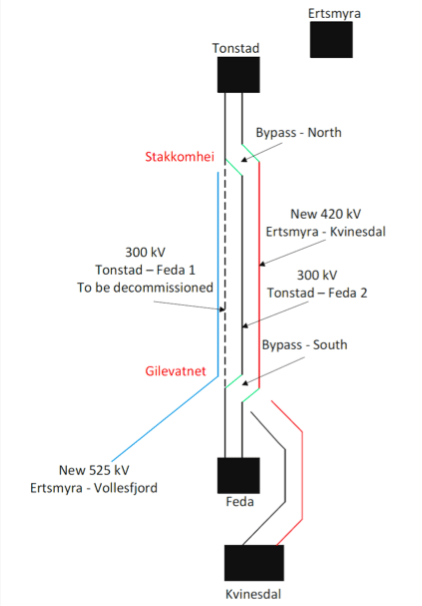
Basically, the new triplex line was finalized between two points, Feda and Tonstad, following which the bypass was established. At that time, de-commissioning of the simplex line between the bypass points near Feda and Ertsmyra could start and work could also begin on upgrading the duplex line. A sequence diagram was established for the Package 1 contractor to fulfill these diverse transmission requirements, making this truly a system operator driven project.
CLICK TO ENLARGE
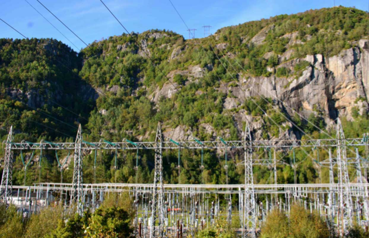
Apart from the new Ertsmyra Converter Station, a new 300 kV and 420 kV switching substation has been located in Kvinesdal, not far from Feda. To allow for clear interfaces and avoid any chance of conflict from overlap, the guiding principle was that completion of stringing work by the transmission line contractor had to be completed beforehand. This allowed the contractor awarded the substation project to do their work unobstructed.