Statnett, the Norwegian TSO, has recently been in the process of network expansion along its Western Corridor – the transmission grid in the country’s southwest. This multi-billion dollar project has spanned several years and has been completed in stages, referred to as ‘Packages’. Package 1, for example, saw existing lines re-routed or dismantled and also construction of an entirely new 420 kV triplex line as well as a new HVDC line. The project was intended to ensure sufficient transmission capacity to serve southern Norway during any outages needed in repair situations or in regular operation and so that the expected 10 TWh growth in supply of hydroelectric power can be connected to the grid. It was also aimed at assuring enough transmission capacity for realization of one interconnection to Germany (NorNed) and one to the U.K. (NSL). The latter, at 720 km, will become the world’s longest subsea cable. As such, the rapid growth in the region’s network was propelled by Statnett’s strategy of assuring the grid capacity for connection of new renewable power and planned cable interconnections.
All this work has been done against the backdrop of the country’s challenging climate and topography as well as a long coastline that exposes some lines to winds carrying contamination inland. These factors influenced insulation and line design. Yet another constraint has been doing whatever necessary to secure public acceptance of lines that pass near sensitive areas such communities, nature trails and animal migration routes. INMR visited construction sites in September 2016 and met Statnett engineers as well as staff at the Croatian contractor awarded the turnkey contract for Package 1.

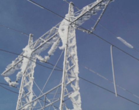
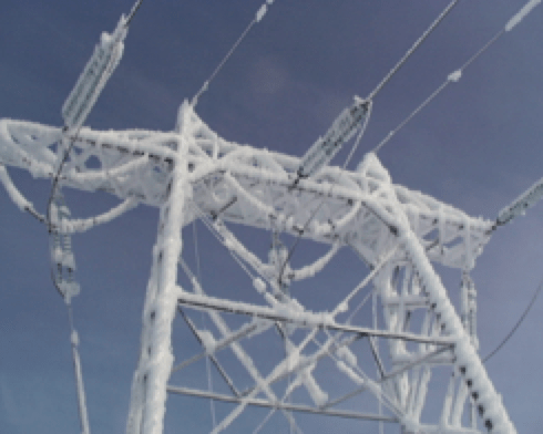
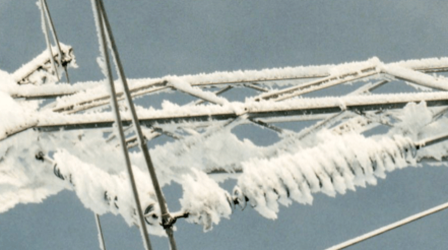
When it comes to transmission line design in Norway, the issue of icing is never far from mind. Indeed, this Nordic country of just over 5 million faces one of the most severe icing environments found anywhere. Statnett Section Chief at the time, Kjell Halsan, reported, for example, that investigation of one recent line collapse revealed an ice load of 70 kg per meter of conductor. In another case, shield wire on a 420 kV line snapped only two months after being put up – again due to excessive ice loading. Said Halsan, “we design our lines for 25 kg of ice per meter of conductor and each span has its own ice load calculated up to this limit.”
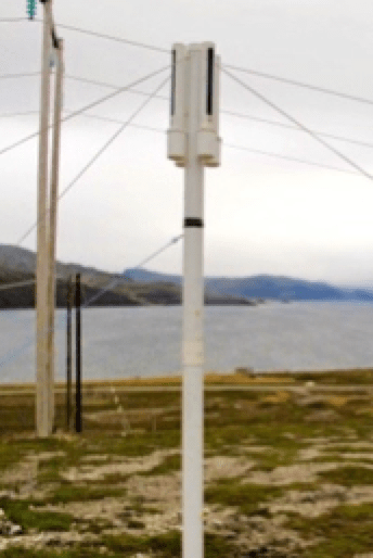
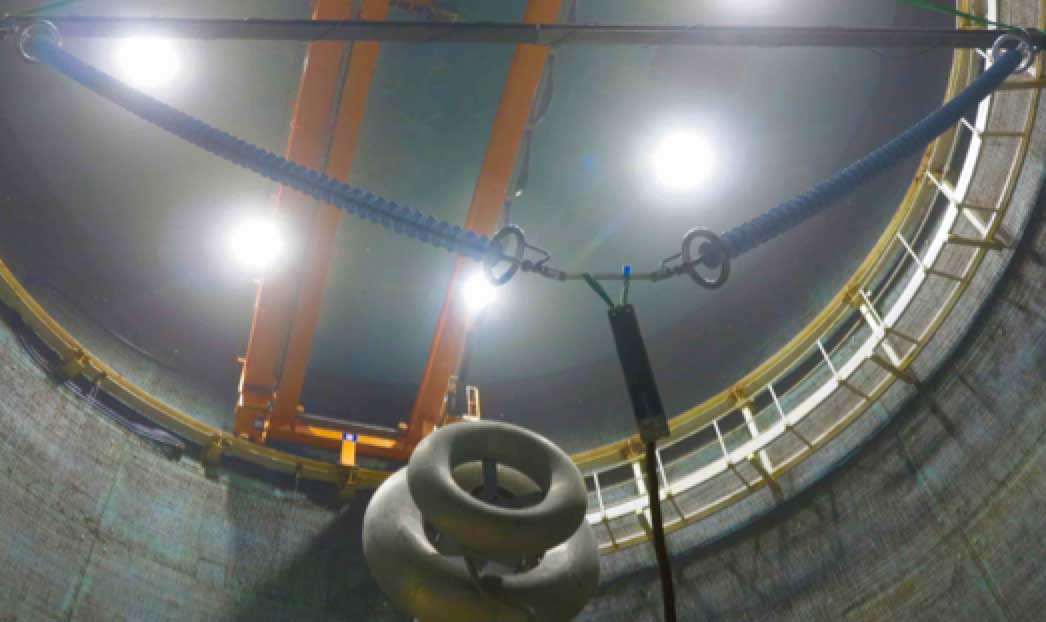
Given the extent to which icing can affect line performance, a decade ago Statnett set up a special test facility to gather data on its comparative impact on alternative insulator designs. Different insulator options were installed alongside a weather-station as well as web cameras and ice load monitors.
Among the goals of the installation was to verify results obtained during simulated laboratory tests. Another was to gain more field experience in regard to snow and ice coverage on various insulator profiles and also to compare swing angles under precipitation and wind. Environmental conditions including temperature, precipitation, ice load and wind speed were all monitored and images taken of insulators at 10-minute intervals. From these, swing angles and ice coverage were estimated using the latest in automatic image analysis. Moreover, all measurements and images were made available to engineers via an interactive website.

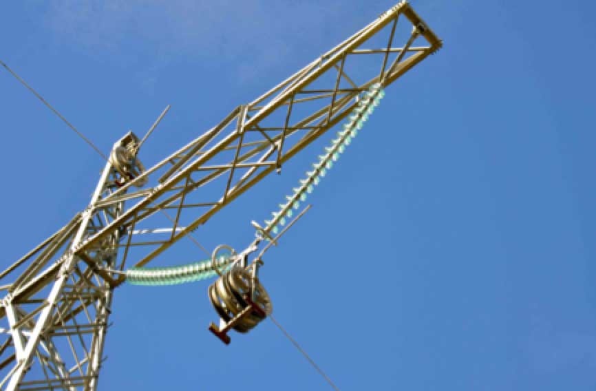
Another key factor in line design in Norway is dealing with the constant threat of galloping given the type of ice and wind loads being faced. Among the techniques most used to limit galloping is application of composite interphase spacers. There are also numerous long spans that traverse valleys and fjords. For example, a 5 km line crossing the famous Sognefjord is one of the longest in the world and employs a special conductor up to 57 mm in diameter. Halsan reported that Statnett has begun work with new types of conductors, each having its own unique tower to allow for the clearances needed between the phases. “But to do this”, he explained, “information was needed on wind conditions and related cooling of conductors. We relied on a system that uses laser-based technology to monitor the speed of aerosols, such as salt particles, in the fjord.”
CLICK TO ENLARGE
CLICK TO ENLARGE
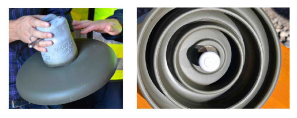
Pollution is yet another important design criterion. For example, a major salt and ice event back in 1993 blacked out several lines in southwest Norway. Therefore, efforts have recently been devoted to establishing ESDD levels at sites where strategic new lines are planned. One noteworthy project where assessing pollution exposure is critical to line performance is the new ±525 kV line that transports renewable energy through an undersea cable link to Germany. To accomplish this, Statnett co-operated with researchers in Sweden who set up a small number of directional dust deposit gauges (DDDGs) test sites. A DDDG is comprised of four vertical tubes, each with a large slot of standard dimension cut into its sides and arranged to face all four directions on the compass. A removable cylindrical receptacle at the bottom of each tube collects wind blown particles that enter the slots. Before containers are removed for analysis, the sides are sprayed to ensure that whatever particulate matter adheres to them is washed down into the appropriate container and included in the analysis. The DDDG’s efficiency in collecting dust is greatest for relatively coarse particles and correspondingly less for fine particles that the air stream typically sweeps around the gauge. Nevertheless, this same physical process is inherent in deposition on any objects in the path of wind and therefore offers a valid simulation of how contamination deposits on insulator surfaces. The volume of material collected in each receptacle depends mainly on wind direction and is greatest when it blows directly into the slot and lowest when it comes from a perpendicular angle. That means that the DDDG is also effective in indicating from where contamination most impacts a particular line or substation and helps identify the local pollution sources of greatest concern.
According to expert Igor Gutman, research for the new HVDC line involved three DDDG installations with 12 measurements taken at each. He admitted that this was a relatively small base on which to estimate varying ESDD levels over a typical year. “Therefore, to expand these readings,” he explained, “we reviewed the previous six years of meteorological data on wind and precipitation at each site. That allowed us to ‘back-calculate’ what ESDD values would have been in those locations over the years since this parameter is primarily a function of wind and rain.” Gutman went on to state that, based on these estimates of pollution exposure, insulators for the new HVDC line were calculated to require a specific creepage of 30.5 mm/kV for inland locations and 37.5 mm/kV for coastal locations. Still, to be conservative, the higher value was eventually selected to insulate the entire line. Halsan emphasized how important the siting of a DDDG is so as to obtain a true measure of pollution affecting any particular line or substation. “If you install them at wrong locations,” he states, “you might not get a valid representation of actual pollution. For example, if they are placed close to the coast but in a place protected by surrounding forest, DDDG readings may not offer good correlation with what actually deposits on lines.”
CLICK TO ENLARGE
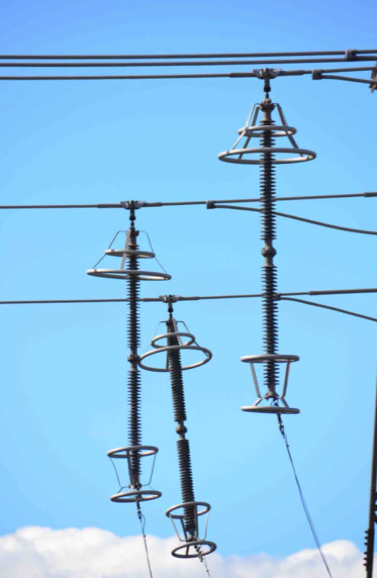
Glass has been the insulator of choice for overhead lines in Norway. The main reasons are that is has performed remarkably well over the years and also offers ease of inspection. Said Halsan, “we specify composite insulators whenever we think they are the best choice, such as for DC lines or for interphase spacers, but we use glass almost everywhere else.” Although glass insulators have demonstrated excellent service performance, certain segments of the public began complaining over the past 10 years about glare from reflected sunlight – particularly when lines pass near nature trails, highways or communities. To deal with this objection, glass discs on such sensitive line sections are pre-coated with a dull green RTV silicone material whose primary role is aesthetic and not improved pollution performance. Halsan estimated that, for new lines built over the past 5 years, normally 5 to 10% of their lengths are special ‘camouflage sections’ equipped only with RTV-coated glass.
CLICK TO ENLARGE
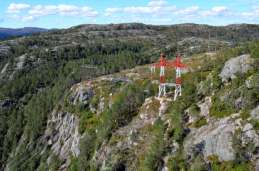
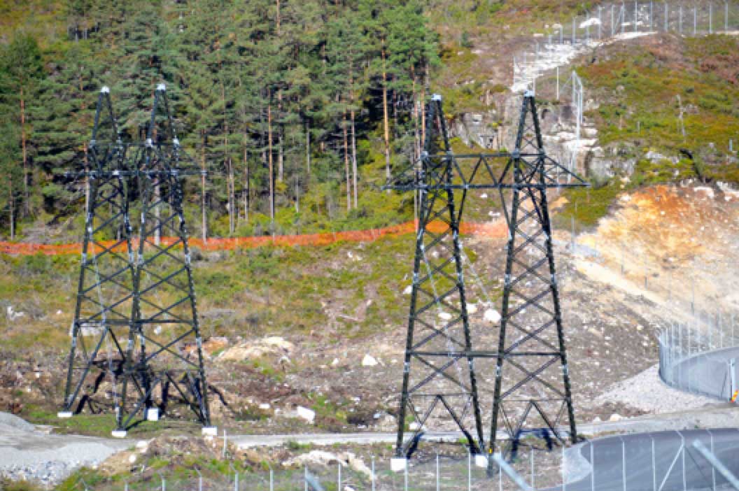
Aesthetic impact has also become an issue for towers and conductors around certain population centers. For example, towers on a relatively short 300 kV line going to the Ertsmyra Converter Substation near Tonstad had to be camouflaged so that they better blend into the surrounding forest.
Similarly, Statnett has been moving to specify only conductor with special dull finish, again mainly to minimize glare. Moreover, in sensitive evergreen forests, painted conductors are sometimes installed for short line sections. According to Halsan, the chemical treatment used adds cost to what he noted is already the single most expensive component – especially in the case of a triplex line. In fact, taking account of all special measures needed for sensitive areas, such as camouflaging towers, coating insulators and treating conductors, Halsan estimated that material costs can increase by up to 50 per cent. At the same time, he noted that treatment of conductors offers benefits apart from only aesthetic impact, including reduced corona due to the hydrophilic nature of the chemicals used. “The net result,” he said, “is that we get not only visual improvement but also audible noise reduction on our twin bundle lines.”

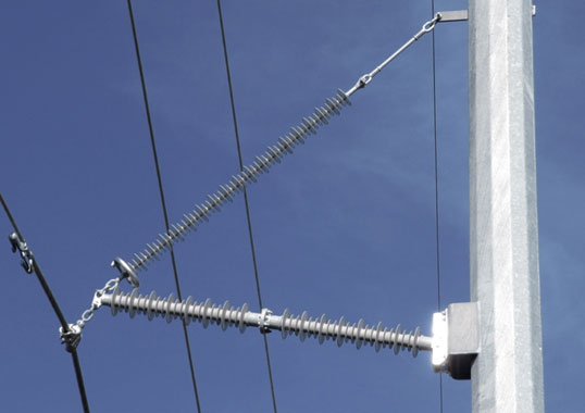
Establishing the most suitable test criteria for insulators is another topical issue at Statnett. Halsan and external consultant Diarmid Loudon, reported that failure rates for glass insulators are typically extremely low. For example, out of 70,000 glass discs installed on one particular line over a 10-year period, only one reportedly had to be replaced. “Maintenance costs are an important factor for us,” said Halsan, “so we look for all ways to avoid unnecessary inspection or repair.” To illustrate what can go wrong, he mentioned one case where the composite insulators selected for a 145 kV line were ‘totally destroyed’ due to what he believes was improper engineering. “When it comes to insulators,” he observed, “we always try to select the best of the best, depending on service conditions.” Perhaps the best example of this philosophy is that, while service experience with glass has been excellent, only composite insulators were selected for the new ± 525 kV line being built in the Western Corridor. Here, superior pollution behavior made such insulators the better choice from both an economic and a line design perspective. At the same time, Halsan injects a note of concern. “What I am most worried about,” he remarked, “is not poor service performance but rather risk of damage to insulators from improper handling, especially since these will be from 5.5 to 6 m long. Also, if there is slight damage, how can we best detect it? Training will therefore be critical and we plan to conduct this for all crews, instructing them in what to do and what not to do.”
CLICK TO ENLARGE
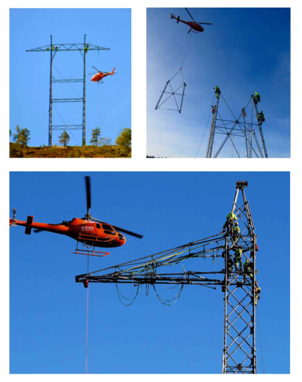
Insulator installation and tower construction techniques are another item of concern at Statnett, not solely from the standpoint of reducing possible damage from mishandling but also for worker safety. “We are looking at methods to minimize the time workers have to spend on towers or conductors,” said Halsan, noting that most accidents tend to happen during stringing.
Package 1 of Western Corridor Project
The Western Corridor Project in Norway’s southwest best illustrates some of these line design as well as construction challenges. Package 1 consisted of 56 km of new 420 kV AC line as well as construction of a 53 km ±525 kV DC line. In addition, 53 km an existing 300 kV line were to be dismantled while a 8.7 km section of another existing 300 kV line was to be re-routed and upgraded to 420 kV. Eugen Hruska has been Project Manager representing the Croatian contractor awarded the tender for the first phase. Standing in a clearing where tower components have been laid out for easy access by helicopter crews, he expressed concern about how workers would handle the 6 m long composite long rods selected for the ±525 kV line.
CLICK TO ENLARGE
Said Hruska, “we had to decide how best to install such long insulators where the fittings are relatively heavy compared to the rest of the unit. This is not such a problem for suspension but more an issue for tension strings. In reviewing our procedures we have focused on best practice methods to minimize the risk of damaging insulators during handling. The other challenge has been worker access to the insulators, considering their relative fragility.”

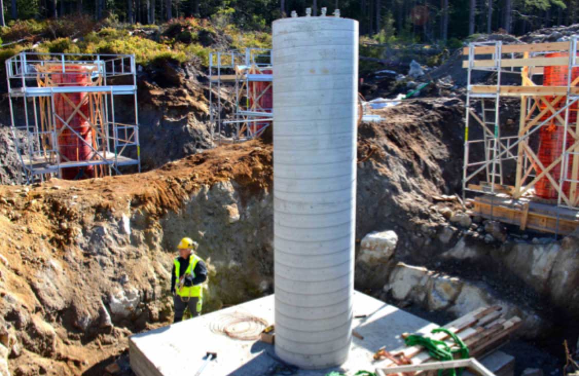
Among the obstacles faced by Hruska and his team were dealing with the highly variable geology found in the area around the site of the new converter substation. For example, this impacted how the foundation for the important terminal tower of the new 420 kV triplex line had to be designed and constructed. “In general, foundation construction along the entire line is closely monitored by a geologist during all phases,” he remarked. “Rock-soil classification is made against 5 different classes of conditions, which then form the basis for each foundation design.”
CLICK TO ENLARGE
CLICK TO ENLARGE
CLICK TO ENLARGE
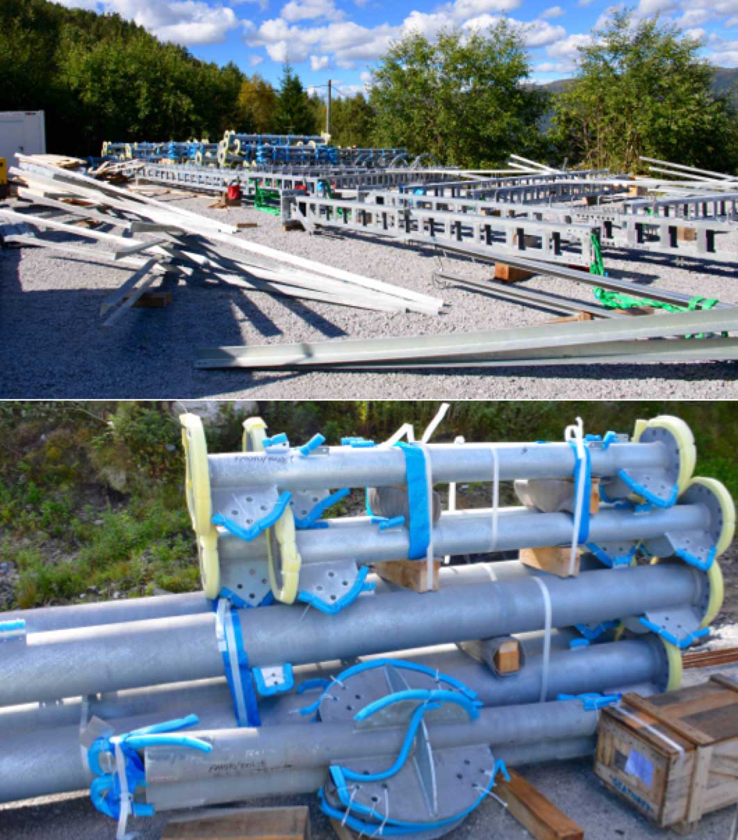
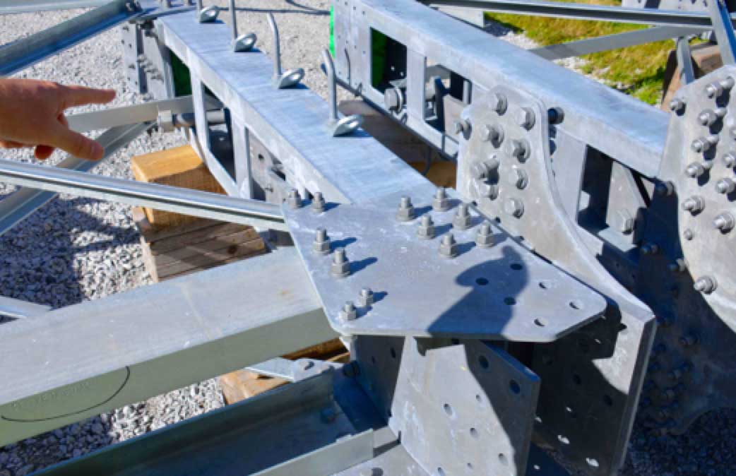
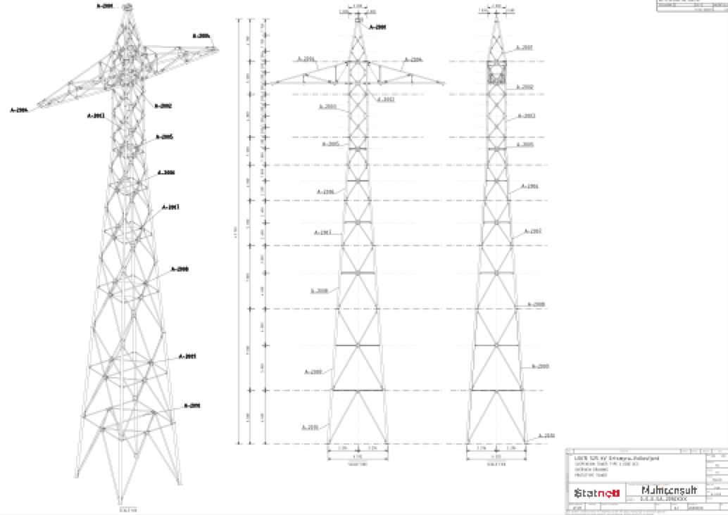
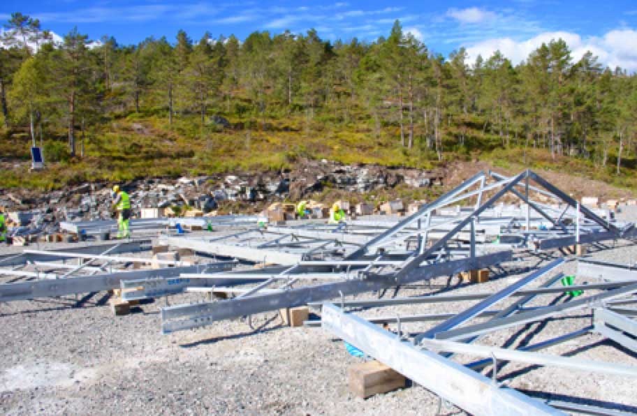
Near the new converter station was one of the circa 30 pre-assembly areas, varying in size from 500 to 5000 sq. m, where tower sections were stored and assembled before being lifted by helicopter to sites in the hills beyond. Hruska noted that each such area serviced nearby tower erection teams and that all assembly procedures were optimized with the goal of minimizing the time needed for every different module. Also stored at this particular location were circular hollow sections for the ±525 kV line towers, which became the first entirely new type of structure used in Norway in 25 years. Loudon noted that this tower design was selected for the HVDC line because it offered high strength in relation to weight. “But the tricky part,” he noted, “is that all connections needed flanges or connector plates.” Hruska added that these tower sections are supplied with pre-loaded bolts whose tightening must follow a strict pre-determined sequence. The new towers stand up to 50 m and weigh 23 tonnes on average for tension and 14 tonnes for suspension.
CLICK TO ENLARGE
CLICK TO ENLARGE

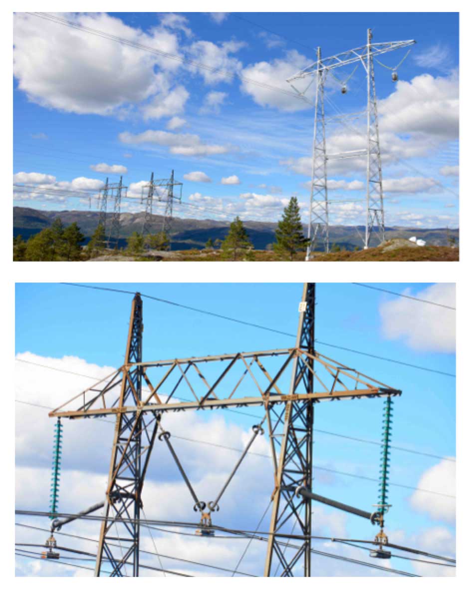
A second pre-assembly site was located on a mountain closer to two existing 420 kV lines that were upgraded in recent years from their initial design voltage of 300 kV. The upgrade involved extension of glass strings and in some cases installation of composite support insulators. In addition, composite struts as well as weights were added to prevent excessive swing under wind load of the I-strings on both outer phases.
CLICK TO ENLARGE
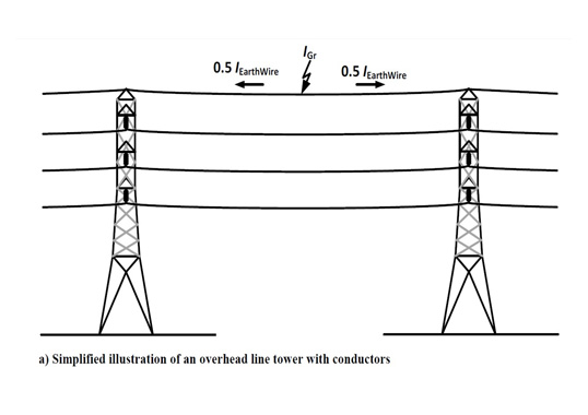
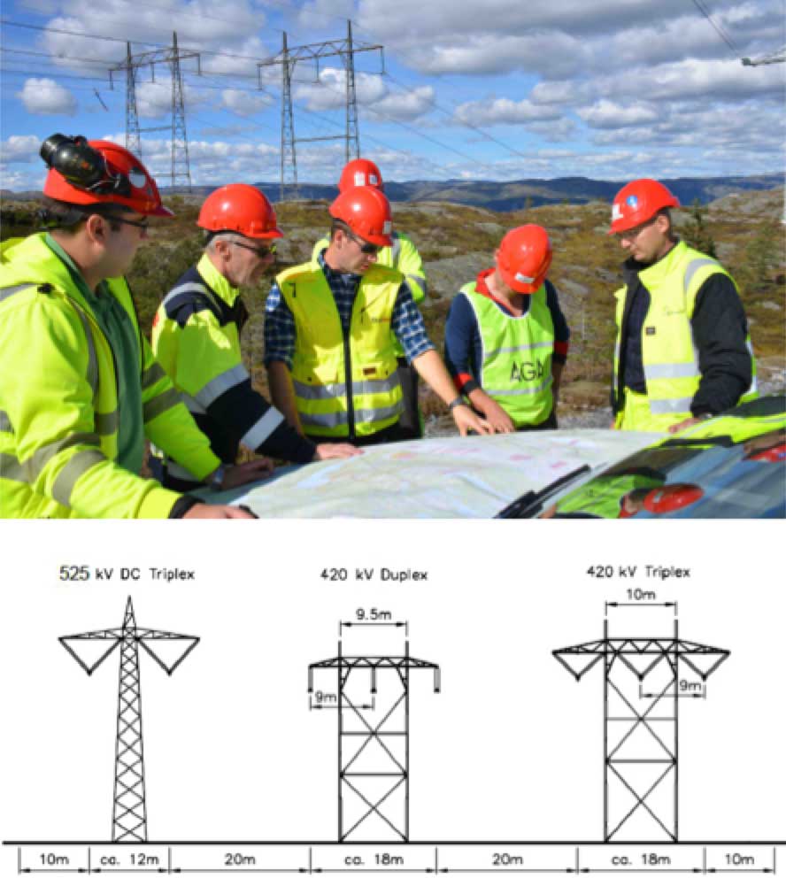
Halsan looked up at the old lines, one of which will be taken down, and remarked that these represented Statnett’s first application of 300 kV line arresters. The units were installed after removal of the earthing between the towers with the goal of preventing any double failures on parallel lines that run only about 9 m apart.
CLICK TO ENLARGE
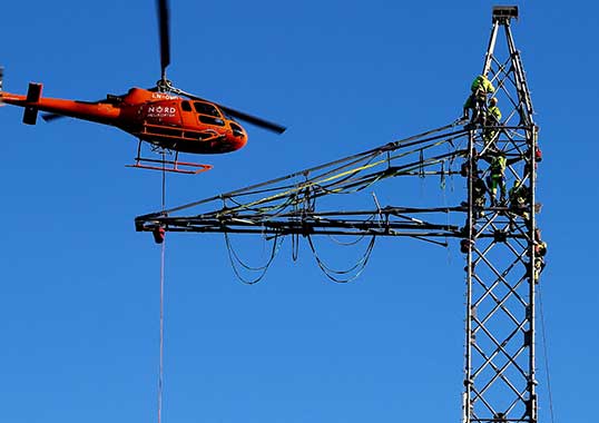
According to Hruska, dismantling one of these lines was one of the biggest challenges faced in Package 1 since the two parallel lines are only 9.5 m apart. This observation was put into better context by the fact that his team would also have to build about 150 foundations, put up some 2000 tonnes of steel and conduct 48 km of stringing operations. Planning helicopter time was another challenge, especially given highly variable weather in this rugged area of Norway. “To keep the project on schedule,” he said, “we have had to use every good flying day to the maximum. The line is about 55 km long so we tried to keep ahead of the weather along each section to look for the best flexibility.”
CLICK TO ENLARGE
Another part of the work in Package 1 involved putting up new RTV-coated glass strings along the sensitive 4 km long 300 kV line near Tonstad where the concession for new lines required application of only non-reflective insulators. Hruska stated that each such disc is supplied in a separate carton to avoid past problems of units scratching each other when packed together in a single container. This, he noted, solved one problem but created another since inventory now had to be stored indoors at assembly areas to avoid the cartons becoming wet and sticking to the RTV material inside. Halsan noted that the cost of these special ‘aesthetic discs’ is at least 50 per cent higher than normal glass and in this case offered no added electrical performance benefits given that it is mostly a clean area. What he pointed out as critical to lifetime of the coating is that the glass surface beneath be perfectly clean. If not, coating lifetime can be significantly reduced and, indeed, some past coatings have been known to peel off even before installation. Said Halsan, “we regard coated glass as the better alternative to specifying composite insulators whenever there is an issue of avoiding glare from reflected sunlight since we are concerned that composite types might fail in such remote areas.”
Part 2 of this article, which appears in next week’s INMR WEEKLY TECHNICAL REVIEW, will present the scope of work for the 420 kV line re-routing and dismantling and also discuss key issues that affected design of the new HVDC line.