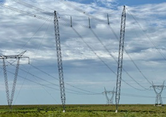
Cross-arms on transmission and distribution structures, whatever their material, can experience deterioration from factors such as rot, rust and tracking. At the same, heavy cross-arms can be difficult to transport to remote areas when lines are being built or refurbished. With these considerations in mind, a Canadian-based insulator manufacturer has proposed innovative solutions to replace traditional cross-arms with fully insulated framing.
This edited past contribution to INMR by A.J. Carreira, Chief Innovation Officer at K-Line Insulators, reviewed insulated framing solutions intended to overcome problems linked to traditional cross-arms.
The insulated framing solutions that have been introduced as alternatives to traditional cross-arms incorporate robust materials and designs that are both light and modular. Moreover, the silicone insulators used in these applications utilize a proprietary material formulation tested and proven for over many years across different types of service environment. Due to savings in required assembly and set-up labour time, these designs offer major cost reduction opportunities over traditional line designs.
Solutions for transmission applications include designs that allow for overhead ground wires while lightning arresters can be installed on such systems in both distribution and transmission applications. These systems have also been designed to resist bird nesting and wildlife bridging from energized lines to conductive metal or grounded cross-arms. These insulated framing systems even reduce risk of failures linked to vandalism or micro defects in ceramic dielectric materials.
The new designs combine insulators assembled into configurations to perform not only the insulation function of a structure but also the mechanical cross-arm function and have demonstrated their potential to replace most cross-arm configurations. For example, review of insulated framing systems for transmission lines confirms technical advantages when used to replace common H-Frame, Gulfport and similar pole and cross-arm framings using de-energized or live line work methods.

Insulated framing solutions developed for H-frame and Tri-frame systems maintain standard horizontal and vertical conductor spacing and clearances based on voltage and span length of each application. They are also adaptable when replacing cross-arm framing on any three-phase line. In some cases, the design can even be used for multiple circuit arrangements.

Distribution Insulated Framing
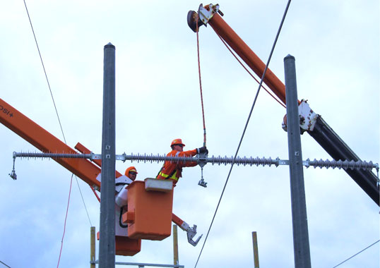
Trial installations of the distribution tri-frame insulated framing design were conducted at the training facility of a major Canadian utility in the province of Alberta. During these trials, it took only about 6 minutes for line crews to lift the pre-assembled unit and bolt it into place at the top of the pole. This significantly reduced installation time compared to construction of a traditional cross-arm arrangement that can take anywhere between 40 and 80 minutes, depending on configuration and crew type. Moreover, the installed cost of this framing solution proved competitive with conventional cross-arm installation.
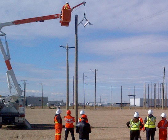
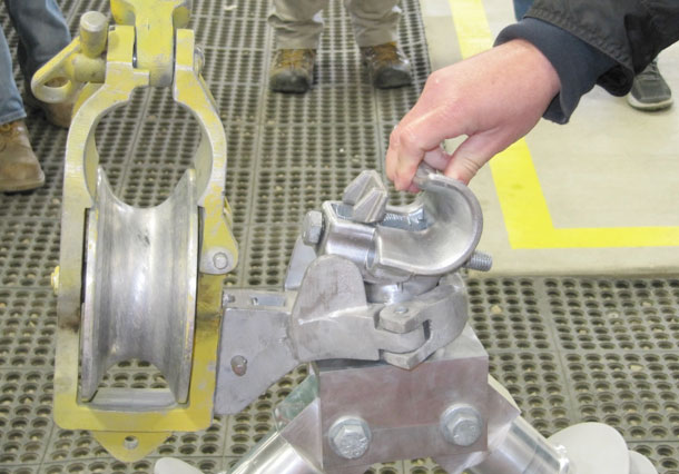
While the above design is complete with the proprietary K-CLAMP®, other conductor end fittings can also be used with the system. These distribution insulated framing systems can be customized and are available for common distribution voltages, including 69 kV.
Transmission Insulated Framing
Similar to distribution designs, insulated framing solutions for transmission lines are intended to offer superior performance compared to traditional treated lumber, steel or composite cross-arm materials. These configurations are designed to perform both the cross-arm and the insulation function on H-frame, Gulfport and other structures supporting nominal voltages up to and including 230 kV.
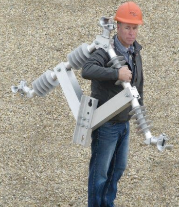
Flexibility is one of the key characteristics of such designs for transmission applications given that the silicone insulator framing design can be delivered either as modular components or factory-assembled as a single-piece system. Among the maintenance-related advantages of such modularity is that, if needed, any single component is simple to replace in situ, without having to remove the complete system and using appropriate live line tools and techniques. Moreover, in difficult to access areas, line crews can transport the light modular components for on-site assembly with no need for cranes or helicopters.
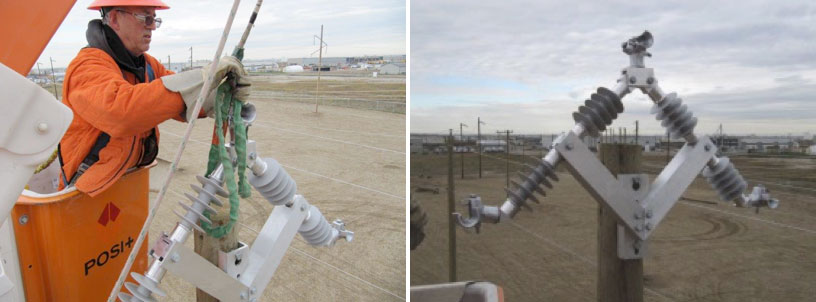
Simplicity of installation is another aspect of this system which, when acquired as a single-piece assembly, can be easily and safely hoisted to position and quickly bolted to the structure with two machine bolts per pole. Installation time and cost are therefore minimized when placing the framing system into position and attaching it to conductor hardware. Integrated connection points facilitate attachment of standard clamps and conductors directly to the insulated framing system, thereby eliminating need for suspension insulator strings. During one trial installation at a utility in Ontario, for example, the time needed to install this system was only about 22 minutes – extremely short compared what is normally required to hoist and install a conventional cross-arm arrangement to a structure.
Moreover, installation of cross-arms typically requires assembling suspension strings and then attaching these (or polymeric suspension insulators), the hardware and the conductors. In addition to the labour costs linked to this work, expensive high capacity lifting equipment is often needed to install cross-arms adding further cost when using traditional framing. By contrast, crews from a Canadian utility were able to demonstrate easy, economical and safe installation of a transmission insulated framing system utilizing live line work techniques.
Another important benefit when replacing conventional cross-arms with such transmission line insulated framing is that vertical line clearance to ground or underbuilt facilities is increased (see Fig. below)
![]()
One way to exploit this added clearance is to allow for greater conductor sag, which permits increasing operating current and thus line capacity. This is achieved when the insulated framing system’s arm is installed at existing conventional cross-arm positions on poles and offers an opportunity to gain vertical clearance equivalent to the length of the suspension insulator string. For example, replacing cross-arms on a 115 kV line makes it possible to gain about a meter of clearance and about 2m can be gained in the case of 230 kV lines. Table 1 demonstrates the potential to increase conductor capacity of an existing 115 kV line by installing fully insulated transmission framing.
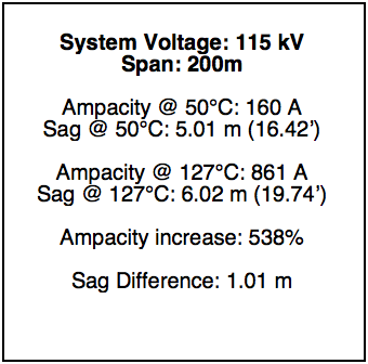
The above illustrates the significant increase in line load capacity made possible when replacing conventional cross-arms with transmission insulated framing designs. Alternatively, apart from using the added clearance to increase ampacity, transmission insulated framing systems also offer opportunities to add circuits to existing or new two pole structures. This benefit is especially important these days due to the difficulties related to acquiring new right-of-way routes. With a transmission insulated framing system, the added clearance can be used to install a second (or more) new circuits positioned lower on the structure. Such additional circuits would be considered new assets and significantly increase the value of existing transmission lines.

At the same time, constructing a new transmission line using fully insulated framing systems makes it possible to erect shorter poles than in the case of the conventional two-pole, cross-arm framed design. This is an added opportunity for cost savings. Also, since fixed positioning of conductors on the insulated framing eliminates need for suspension insulator strings, it also eliminates insulator swing under transverse wind conditions.
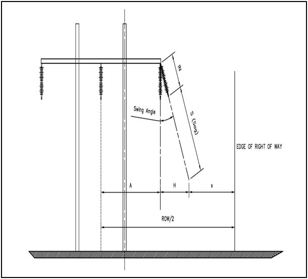
The benefits of eliminating this displacement component include using existing ROWs more efficiently and reducing land or easement acquisition costs when constructing new lines. It also means that separation distance between phases and structure can be reduced. These reductions in structure width and height allow for design of more compact lines that use fewer materials and require much narrower ROW, both of which contribute to reduced construction costs. Compact lines are also considered more aesthetic. If needed, optional brace insulators can be added to basic insulated transmission line framing.
Such bracing can increase mechanical load capacity of the system by up to 80%, depending on design. Specific increase in load capability depends on the angle between the insulated framing system’s horizontal component and the supporting brace insulator. Increased load then permits longer span lengths, fewer structures and reduced line costs.

Mechanical Testing
Development of insulated framing required testing to determine the performance capabilities of each design. Various mechanical tests were conducted on both the distribution and transmission TIF arrangements. Some of the tests were conducted to determine the maximum vertical, longitudinal and transverse load capabilities of each framing.
1.Distribution Framing Systems
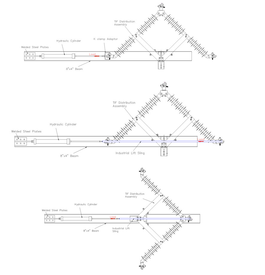
To verify the strength of the Distribution TIF design, the appropriate loads were applied at each framing load location. Some of the test arrangements are illustrated in Fig. 12.
A couple of the actual load test set ups are illustrated in Fig. 13.
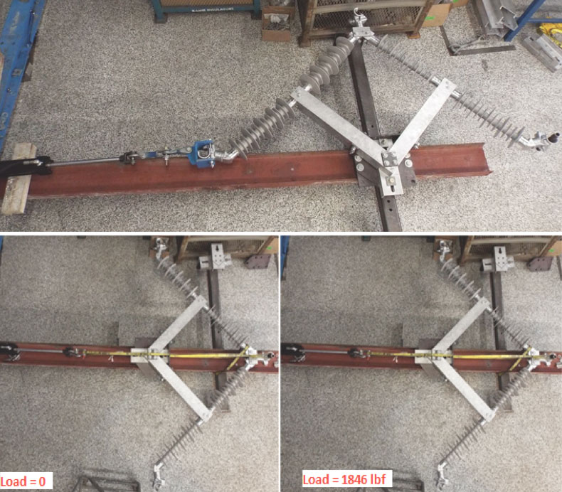
The test results indicate that the Distribution TIF designs meet the MDCL requirements without any noticeable deformation. The test results also indicate the framings can reach and exceed the SCL mechanical load requirements without failure.

2. Transmission Line TIF Systems
Appropriate testing similar to that conducted on the Distribution TIF was also conducted on the Transmission TIF arrangements. The testing of most interest was to determine what affect the cantilever loads would have on the TIF pole connector plate assemblies and the mid connector plate hardware. The arrangements (refer to Fig. 14 as an example) were tested for their mechanical suitability under cantilever loads as compared to the transmission line post insulators.
The above pictorial load test set up is illustrated in Fig. 15.
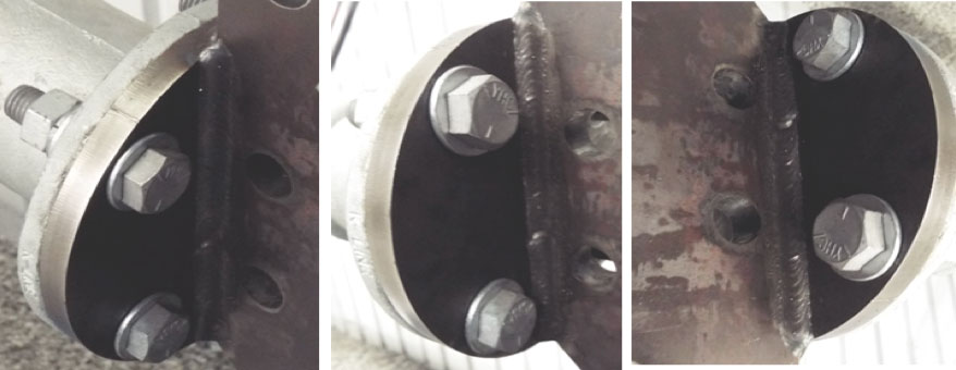
All test results indicate that the Transmission TIF designs meet and exceed the mechanical load capabilities of the transmission line post designs offered for each engineered framing system. As illustrated in Fig. 16 for example, the mid connector plate assembly withstood the testing without deformation, cracks or other damage.

Conclusions
Replacement of deteriorating cross-arms on power lines has become a growing problem for utilities. With this has come the need to develop safer and more efficient framing to maintain dependable uninterrupted power supply. Live line work methods are now the preferred approach when conducting most maintenance activities, including replacing degraded cross-arms.
Insulated framing designs and materials offer new opportunities for electricity providers and contractor personnel to safely and efficiently meet these maintenance and performance requirements. Fully insulated framing requires significantly less labour to erect compared to traditional cross-arms and line crew work exposure (energized or de-energized) is greatly reduced. Insulated framing designs for both distribution and transmission line applications provide advantages, benefits and cost savings over conventional cross-arm framing arrangements and also contribute to system reliability and longer service life of assets. Moreover, these systems can be customized to meet the requirements of a range of different system voltages.

References
[1] A.J. Carreira, “Insulator Inspection”, 2015 INMR World Congress, Munich, Germany, October 18-21, 2015.
[2] A.C. Baker, R.A. Bernstorf, E.A. Cherney, R Christman, R.S. Gorur, R.J. Hill, Z. Lodi, S. Marra, D.G Powell, A.E. Schwalm, D.H. Shaffner, G.A. Stewart and J. Varner, “High Voltage Insulators Mechanical Load Limits-Part I Overhead Line Load annd Strength Requirements”, IEEE TPWRD-00043-2011, January 2011.
[3] A.C. Baker, “Design and Application of Braced High Voltage Insulator Assemblies”, DEIS IEEE Electrical Insulating Magazine, March/April 2010.