Composite insulators have become the dominant type selected for use on overhead lines and have also been growing rapidly in application at substations. But this development required five decades of service experience as well as several generations of products before the technology could finally come to be viewed as offering equal reliability to toughened glass or porcelain.
In this edited past contribution to INMR, Dr. Frank Schmuck, an expert with over three decades experience in design, production and testing of composite insulators, reviewed how the combination of research and learning from field experience helped identify and resolve past deficiencies.
The first polymeric insulators were developed during the 1950s and consisted of monolithic designs made of structural materials such as epoxy. At the time, conventional porcelain and glass insulators were state-of-the-art and indeed the first IEC standards were being issued to assist in their specification (i.e. 1st Edition of IEC (60)075 in 1955 & 1st Edition of IEC (60)087 in 1957). By contrast, composite insulator technology for transmission applications greater than 100 kV was not seriously considered until at least 25 years later.
The basic premise of a composite insulator is that different materials, when combined, contribute to enhanced functionality based on their respective key properties. For example, the fibre-reinforced plastic (FRP) rod or tube provides for mechanical strength while the polymeric housing offers protection against harsh environments. Both also contribute to the basic function of electrical insulation. The real ‘push’ for these insulators began in the 1970s and was initiated by progress in both FRP and housing materials. Also, new manufacturing technologies were introduced to produce fully assembled insulators and these included improved processes to mold housings over rods/tubes as well as to attach end fittings.
During their period of introduction, composite insulators were regarded as highly specialized and even called “exotic”. They were also comparatively costly due to the low numbers produced, often made from non-standardized, semi-finished components. As such, initial use was limited mostly to special applications such as for areas with extreme pollution, vandalism or high seismic risk in the case of apparatus insulators. As typical for such innovations, there were few if any standards and long-term operating experience available to users was limited. As a result, it was not unusual to encounter a series of design errors that ended in corresponding service failures. One well-known example was lack of understanding of possible sealing problems in general and in particular in the case of Teflon-housed insulator that had no bond between housing and rod. Instead, this critical interface was filled with grease that disappeared after a relatively short time in operation. This insulator design failed relatively quickly due to flashunder, rod tracking or brittle fracture caused by moisture ingress.
Since that time, composite insulator technology developed progressively as an alternative to porcelain or glass due to superior performance in certain applications. At the same time, it began to acquire a reputation for successful operating experience across the globe and production quantities soared. It is worth noting that the today’s state-of-the-art of this technology can be largely attributed to pioneering work done by several international manufacturers as well as by a small group of utilities who recognized the potential benefits and took the risk of installing composite insulators on their networks to gain service experience. Research institutions such as universities and laboratories also participated in identifying and understanding dynamic interactions between housing material and the environment as well as the mechanisms behind mechanical damage mechanisms. This allowed deducing models of these different possible behaviours.

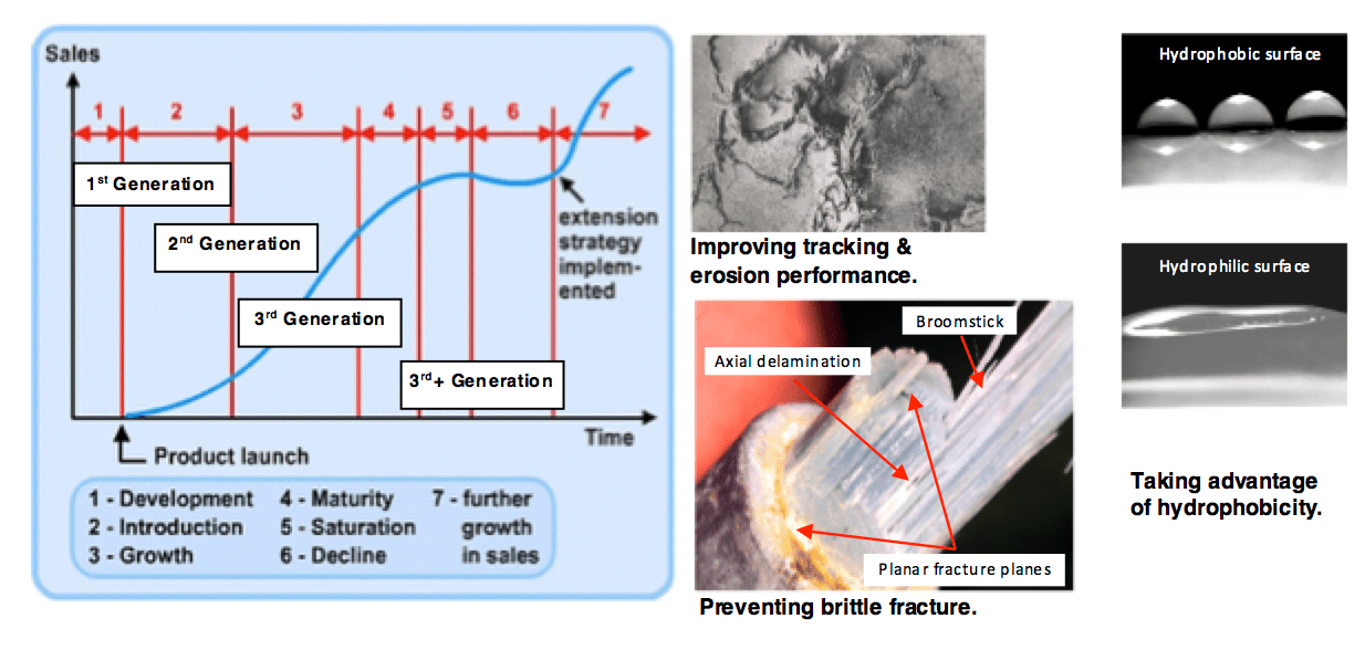
Composite insulator technology has undergone several distinct development and standardization stages, which is common for such technical products. The insulators manufactured today, commonly referred to as ‘third-generation’ or ‘third-generation plus’, are characterized by high-quality components with a history of use. In 1991, the relationship between generation, semi-finished material components and insulator development was initially described and remains valid, with slight refinement:
1st Generation: 1955-1970
Development of dry band and arc-resistant polymeric materials and corresponding test methods to verify this property;
2nd Generation: 1971-1984
Discovery and evaluation of the hydrophobic behaviour of polymeric insulation surfaces and start of use of silicone grease applied to porcelain surfaces;
3rd Generation: 1985-2005
Fundamental investigation of the dynamic interaction between material properties in relation to service behaviour and introduction of test procedures as well as product standards;
3rd+ Generation: 2006 on
Availability of high strength post insulators, optimization of housing material in terms of hydrophobicity and erosion resistance, review and submission of improved editions of composite insulator product standards, development of proprietary housing formulations by manufacturers, and establishment of economies-of-scale in production.
A simplified product cycle model can be applied to development of composite insulator technology with consideration of these different generations along with some differentiation based on application and voltage level. Stages 1 to 4 can be recognized to have passed for distribution voltages as well as some transmission voltage applications. Stage 5 can be identified because of the large number of manufacturers and the corresponding intense competition that has resulted in composite insulators almost becoming a commodity. Stage 6 is not yet prevalent because of new installations worldwide and demand for replacement in terms of maintenance of old lines equipped with conventional insulator technology. Stage 7 can be considered for sustained further development, including large rod diameters for post insulator applications (e.g. 300 to 360 mm diameters), design advantages of hydrophobic composite insulators for DC applications and compact solutions, especially for voltage uprating in existing line corridors.
Mature Technology
Composite insulator technology has now attained a high level of maturity, as can be demonstrated by several factors, including:
• Availability of comprehensive product standards, verified by testing and field experience;
• Worldwide service experience in all types of applications and at all voltage levels;
• Automation of production to increase volumes, reduce cost and lessen risk of human error;
• Quasi-standards for key sub-components, such as E-CR glass;
• Improvements in specific design rules, such as threshold for water droplet corona.
However, a number of risk factors have also come be identified:
• Cost pressures due to intense competition has reduced technical redundancy (i.e. built-in over-design);
• No type testing approval of new designs;
• Lack of power system knowledge among some new suppliers in terms of insulator string and set designs (e.g. permanent corona discharges);
• Installation problems traced to lack of knowledge by workers (e.g. torsion damage to tension insulators);
• Handling and storage problems (e.g. mould growth in crates),
• Technical issues such as silification, mould growth in the field;
• Inappropriate tender documents.
Below are examples of recent achievements as well as identified needs for further research and development:

1. Hydrophobicity Behaviour Under DC Voltage Stress
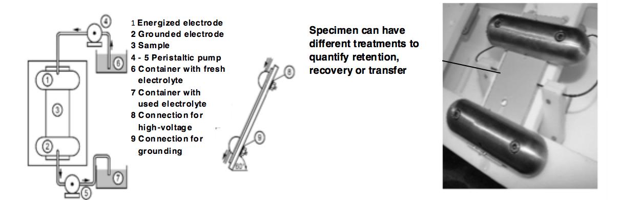
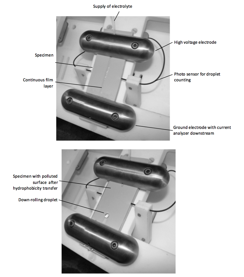
Two scientific projects were completed in Germany to improve the quantification of different hydrophobicity effects (i.e. retention, recovery and transfer). Using a Dynamic Drop Test (see Fig. 2), retention of hydrophobicity against water droplet induced corona discharges is measured by means of time before the failure criterion (i.e. 1 mA) is exceeded for the pre-defined time of 0.25 s.
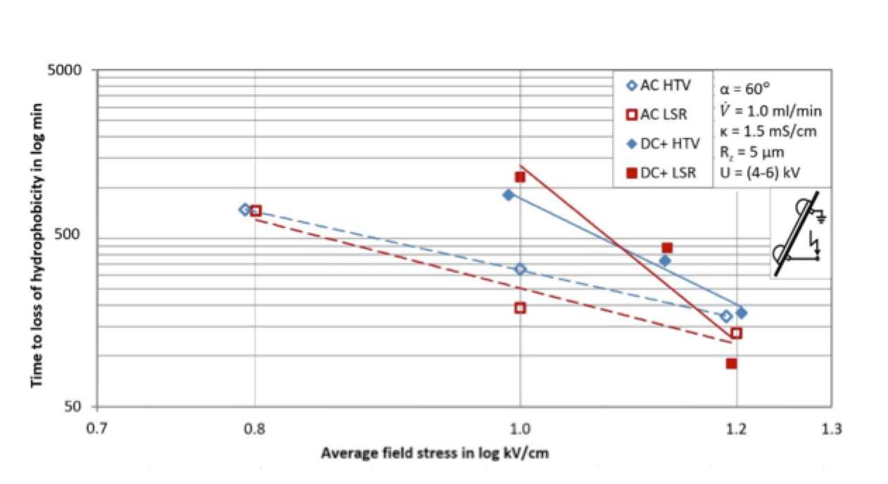
Many parameters were identified that could improve reproducibility of this test, among these the test set-up itself and the test specimens (i.e. methodology of cleaning, surface roughness, etc.). An important result was found regarding retention of hydrophobicity under AC versus DC stress (see Fig. 3). Voltage stress is shown as average field stress (i.e. applied voltage divided by creepage distance). The DC+ curve is above the AC curve, however the DC+ curve is steeper. This trend in the results applied to all materials investigated during these projects. This finding helps explain positive experience with hydrophobic housing materials. This effect was found during tests with stress value ACrms equivalent to DC voltage and is mirrored in service by the fact that more creepage distance is typically used for DC applications than for AC, given the same environment with equivalent pollution level. CIGRE Working Group D1.58 further investigated this in a report, ‘Evaluation of dynamic hydrophobicity of polymeric insulating materials under AC and DC voltage stress’. This work aims to develop an IEC standard for quantification of hydrophobicity and to provide a classification guide for hydrophobicity transfer materials (HTM). This terminology is already introduced in IEC 60815-3/-4 for correcting creepage distance as a function of insulator diameter.
2. Protection Against Corona
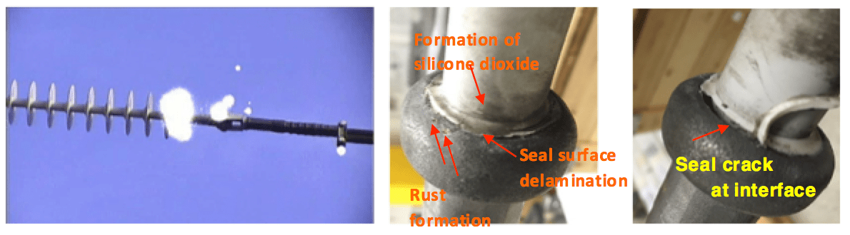
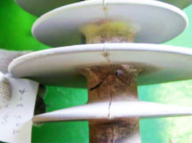
It is widely accepted that thermal effects of corona discharges are negligible. However, permanent corona discharges will create acids and chemical radicals under service conditions and these can attack the galvanization on fittings as well as the polymer housing. Given long experience with all insulator technologies, corona discharges caused by inappropriate string design should no longer be expected. Unfortunately, reality shows that there may still be such problems at lower transmission voltage levels due to intense competition with the result that corona rings are seldom used at voltage levels ≤145 kV. This finding has also been identified by an IEEE task force. Such work has triggered new rules for electric field stress thresholds to prevent continuous hardware corona as well as water droplet corona. Today’s computers and available simulation programs are so powerful that insulator string designs can be confirmed digitally. However, when using new designs and components, including a new supplier or production location, laboratory re-testing of ‘critical’ designs is recommended. A practical example of an under-dimensioned tension string in service on a two-phase AC system (145 kV and 16.7 Hz) is shown in Fig. 4. Even under fair weather conditions, this string design caused permanent corona discharges with such intensity that these could lead to malfunction of electronic controls at the substation. Some insulators were provided for close-up visual inspection. As expected, the groundside that was corona-free showed no damage whereas there was clear evidence of damage on the energized side. Depending on corona intensity, this type of damage can appear after only several months. In particular, the seal design in this case was particularly sensitive to discharges because the triple point is close to the seal and seal materials are only low-filled polymers.
3. Further Development of Silicone Rubber for Outdoor Insulation
Experience with composite insulators having polymeric housings has been available for some 40 years and there is a clear trend that silicone rubber has become the material of choice. One reason for this is long-term and dynamic hydrophobicity effects. This even becomes a cost-savings factor in service areas with heavy pollution where regular washing of conventional insulators would be required. Service experience, however, has also shown that further development of silicone rubber formulations is required in certain aspects. Three key areas that are the focus of current development work are surface silicification, deep surface cracking/splitting and mould growth on surfaces.
Silicification
Surface silicification is a synonym for surface deterioration that causes layers of silica oxide on the surface of a housing. Measurements on field-aged insulator surfaces showed typical thicknesses of between 100 and 300 µm. In contrast to a virgin surface, elasticity of the polymeric material in the cross-section of the silica oxide layer is significantly reduced and in fact demonstrates brittle behavior when subjected to mechanical stress such as bending sheds. If such a deteriorated material is measured with respect to mechanical strength, there is reduction in tensile strength whereas tear strength is not seriously affected. This can be explained by the fact that, when bending, the brittle silica oxide layer breaks immediately and resulting cracks cause a notch effect in the intact bulk material. Examples of silicification on LSR housings of instrument transformers were reported at the 2015 INMR WORLD CONGRESS in Munich (see Figs. 5 and 6). To prevent ingress of pollution and water into these cracks, which would only increase risk of further damage, the LSR surface was sealed by an RTV silicone coating. This remedial measure proved successful and the affected equipment is still in service.
Reasons for such deterioration are not yet fully understood. A Fourier Transform Infrared Spectroscopy (FTIR) analysis has indicated that hydrolytic processes are root cause. LSR material is typically not enriched with aluminum trihydrate (ATH) for improved erosion resistance but instead has silica filler to provide the mechanical properties required. One hypothesis is that inappropriate surface treatment of this filler can lead to the damage observed. However, this is difficult to confirm with vulcanized silicone rubber.
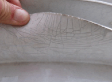
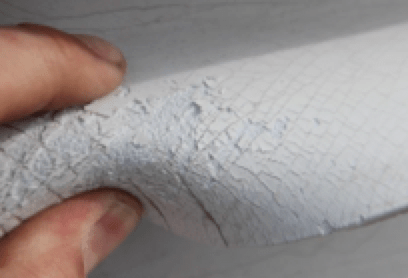
Deep Surface Cracking or Splitting
Deep surface cracking or splitting is a form of degradation marked by severe cracking along the complete housing (Fig. 7). Such damage poses great risk because the rod, which is not outdoors resistant, becomes exposed to the environment. With ingress of moisture and pollution, the interface between housing and rod is attacked and a flashunder becomes likely.
Two aspects have to be considered in regard to these types of potential problems:
1. Evaluation of the deterioration and estimation of risk for continued use of the insulator. As a reference document, IEEE’s Guidelines for Establishing Diagnostic Procedures for Live-Line Working of Non-ceramic Insulators, published in 2014, can be of value. But as ‘rule of thumb’, housing damage cannot be such as to expose the rod.
2. Since such findings represent a ‘current state’, no prediction of the risk of additional accumulated damage can be made. It is therefore recommended that all insulators with this type of deterioration be inspected on at least an annual basis. This should apply to all insulators of that vintage and that are in service in the specific service area. In the case of silicification, if the housing remains hydrophobic, affected insulators can remain in service since the silica oxide layer protects the intact bulk material against further deterioration.

Mould Growth Due to Improper Stocking
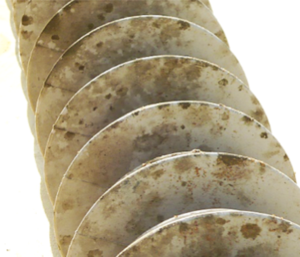
Mould growth on insulators in service is related to interaction of their surfaces with the environment. If a nutritious source, sufficient humidity and temperature as well as corresponding biological species are all present, the surfaces of conventional and composite insulators can become ‘colonized’. The effect in the case of an inert ceramic surface is relatively minor since this material is hydrophilic. As such, mould growth can cause only a certain increase in thickness of the pollution layer. But in the case of composite insulators with a hydrophobic surface, this performance-enhancing property can temporarily be lost. Nevertheless, experience has shown that only in few cases will mould grow to the extent that that a composite insulator has to be cleaned. Moreover, a decision to clean the insulator is taken mostly as a precaution if intense colonization has been identified. This field experience is confirmed by laboratory investigations that have shown that only white rot fungus (Phanerochaete chrysosporium) can degrade PDMS (i.e. the main component in silicone rubber). Recently, cases of mould growth were reported after long-term storage of composite insulators in transport crates exposed to rain and summer temperatures. Such crates are typically made of wood and special treatment (i.e. ISPM 15 – International Standards for Phytosanitary Measures) is typically required before these can be imported into most countries.
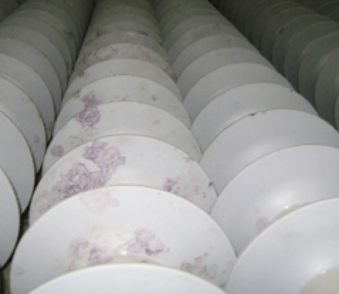
Experience has shown that design of wooden crates calls for a compromise: on the one hand, holes or slots are needed for internal ventilation but on the other hand, sizes of holes should be small to prevent ingress of pollution or creatures. Still, depending on climatic conditions, these crates can suffer short term ageing, especially when left fully exposed. If the insulators inside the crate are unprotected or if the protection has been removed when taking out some insulators, water with organic content from the wood can come into contact with the insulator surface and cause colonization by fungus. A wide variety of species can create such biogenic pollution. For example, insulators can become covered by fungus such as Aspergillus niger and Cladiosporium (see Fig. 8). These species are only superficial and can be removed easily. Colonized areas are restored to being fully hydrophobic after removal. Combined colonization has also been known to occur, such as by the mould species Chaetomium and Cladosporium that somehow have a symbiotic interaction with Methylobacteria. The latter colony creates a pinkish appearance on insulator surfaces (as in Fig. 9). While such mould is easily removed, the pink colour may migrate into the silicone rubber and remain in the bulk material. Surface areas with the remaining other species are hydrophobic as well so there is no functional problem. But aesthetic aspects may need to be addressed. It is worth noting that climate change is making exposed power infrastructure more and more vulnerable to attack by mould and fungus growth.
Conclusions
Composite insulators now constitute an important component in energy transmission worldwide. With more than 50 years of field experience as well as comprehensive product standards with prescribed maintenance cycles, this can indeed be considered a mature technology. However, there are still examples where further optimization of housing formulation may be required.
References
1/ IEC (60)075 Ed. 1. 1955: IEC specification for porcelain insulators for overhead lines with a nominal voltage of 1 000 volts and upwards”
2/ IEC (60)087 Ed. 1. 1957: IEC specification for glass insulators for overhead lines with a nominal voltage of 1000 Volts and upwards
3/ R. S. Gorur, T. Orbeck: Surface Dielectric Behavior of Polymeric Insulation under HV Outdoor Conditions. IEEE Transactions on Electrical Insulation Vol. 26 No. 5, October 1991
4/ S. Ansorge, C. Baer, F. Schmuck: Comparative Investigations of Hydrophobicity Effects and Erosion Resistance of Silicone Rubber used for Housings of AC and DC Insulators. CIGRE Session 2016, Paper B2-352
5/ IEC TS 60815-3 Ed. 1 2008: Selection and dimensioning of high-voltage insulators intended for use in polluted conditions – Part 3: Polymer insulators for a.c. systems
6/ IEC TS 60815-4 Ed. 1 2016: Selection and dimensioning of high-voltage insulators intended for use in polluted conditions – Part 4: Insulators for d.c. systems
7/ IEEE Taskforce on Electric Fields and Composite Insulators: Electric Fields on AC Composite Transmission Line Insulators. IEEE Transactions on Power Delivery, Vol. 23, no. 2, April 2008
8/ V. Sklenicka, K. Fiala, M. Bruckner: RTV Silicone Coating of Polymeric Insulator Housings with Surface Degradation. INMR World Congress 2015 Munich
9/ I. Y. Al-Hamoudi: Field test results of Composite Silicone Rubber Insulators at Shoaiba of Saudi Arabia. GCC CIGRE 2008 Bahrein
10/ A. J. Carreira, E. A. Cherney, R. A. Christman, E. Cleckley, J. Kuffel, A. J. Phillips, J. Varner: Guidelines for Establishing Diagnostic Procedures for Live-Line Working of Non-ceramic Insulators. IEEE Transactions on Power Delivery, VOL. 29, NO. 1, February 2014