Among the goals of power systems these days is that a growing share of energy be supplied from renewable sources. At the same time, power systems have to become more controllable to optimize power flow and reduce losses. The classical power system must therefore continually adapt to allow better utilization of distributed generation, energy storage and information infrastructure. A recent gathering of energy ministers from the world’s largest economies defined the breakthrough technologies expected to revolutionize future energy system infrastructure. These include: HVDC, advanced energy storage systems, ultra-efficient solar power, advanced offshore wind turbine technology, micro-grids, hybrid renewable energy and the internet of things energy management. All these technologies impose more stringent requirements on insulation systems, spe-cifically those operating outdoors, since stresses will only intensify. In this edited past contribution to INMR, retired Professor Stanislaw Gubanski of Chalmers University of Technology in Sweden reviewed directions research efforts have taken and gave examples of past work performed in co-operation with the Royal Institute of Technology in Stockholm.
In this edited past contribution to INMR, retired Professor Stanislaw Gubanski of Chalmers University of Technology in Sweden reviewed directions research efforts have taken and gave examples of past work performed in co-operation with the Royal Institute of Technology in Stockholm.
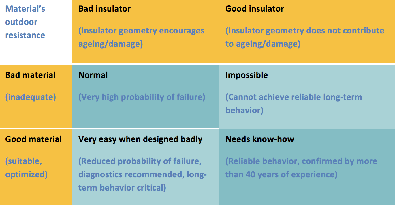
One of the earliest developers of silicone rubber composite insulators, Prof. Herman Kärner in Germany, pointed to the critical interplay between material properties and insulator geometry when he formulated what became known as the ‘Kärner matrix’. In it, he indicated that manufacturing high quality composite insulators is not possible without taking into account two factors – good material and good design. The matrix was later elaborated by Dr. Konstantin Papailiou and Dr. Frank Schmuck (see Fig. 1). Kärner’s principle still remains valid and must continue to be followed in the process of finding suitable optimized materials as well as insulator geometries that best resist ageing and other damage.
The desired direction of present research includes development of materials for HVDC applications as well as introduction of thermoplastic polymers that improve product recyclability.

Material Modifications for Improved Performance
Field Grading Materials
Field grading materials (FGM) using composites filled with conducting and semi-conducting inorganic particles were initially applied in high voltage motors and generators. The concept was later transferred to cable terminations and joints to mitigate critical dielectric stresses. Use of FGM in designs of other power equipment, including circuit breakers, bushings, instrument transformers, surge arresters and insulators is today also highly desirable.
The primary characteristic of a field grading material is that its electrical conductivity increases above a threshold electric field value. This property is then utilized to reduce maximum field stress at critical locations inside the insulation system. A FGM composite is composed of a base polymer (e.g. silicone rubber SIR, ethylene propylene-diene monomer EPDM rubber, epoxy resin or thermoplastic) filled with silicone carbide SiC, zinc oxide ZnO or carbon black. Recent research, however, concentrated on the possibilities provided by nano-fillers, especially graphene oxide (GO) and graphene nano-platellets (GnP). These offer the promise of similar field grading charac-teristics but using much lower filler loads while also provid¬ing better material processing characteristics. For example, results obtained with LDPE-GnP based nano-composites illustrate the features that could be of interest to improve performance of polymer based insulation systems such as an HVDC cable termination. The manufacturing process for the specimens studied was by melt extrusion, an attractive industrial process illustrated in Fig. 2. It includes a precoating technique where exfoliated graphene nano-platelets are first deposited on polymer powder particles to secure good dispersion during melt extrusion. Two types of screws were used during extrusion: a compression screw (CS, compression ratio 2:1) and a mixing screw (MS, compression ratio 5:1).
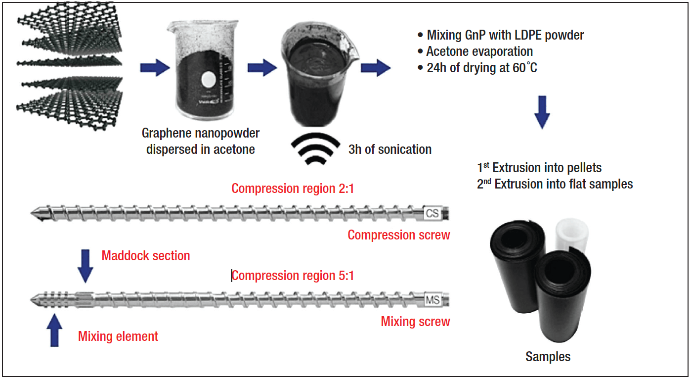
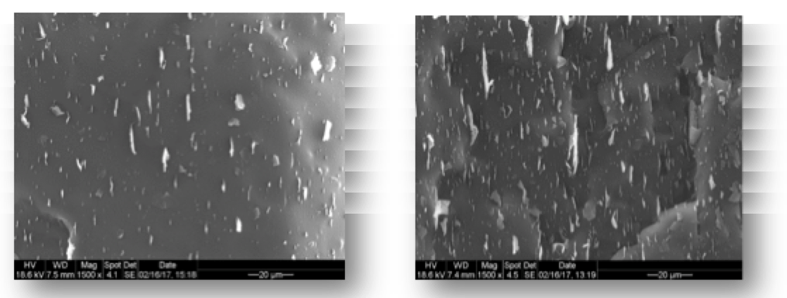
Fig. 3 shows the morphologies of freeze-fractured and etched samples of these nano-composites. The surfaces observed are perpendicular to direction of extrusion, indicating strong anisotropy of filler alignment and uniformity of its distribution along polymer flow in the extrusion direction.
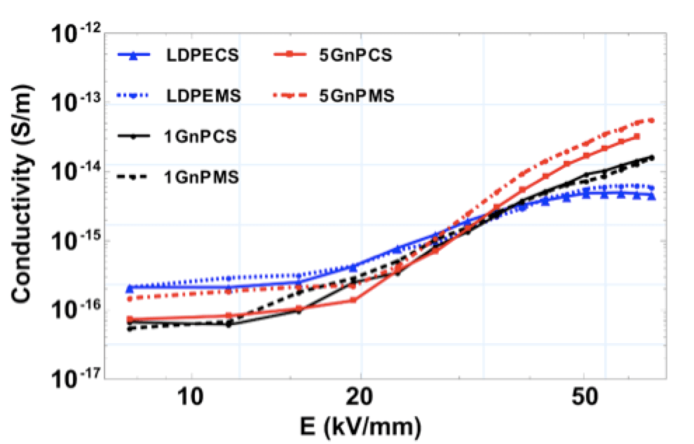
In Fig. 4, field dependence of electric conductivity is compared for all samples investigated. Non-linear behaviour starts to dominate this property at field strength of about 20 kV/mm and a clear ‘crossover effect’ can be seen. A lower conductivity at low fields of the filled nanocomposites turns into a higher one compared to the conductivity of the pure polymer. Similar behavior was reported when adding graphene oxide into a polydimethylsiloxane matrix.
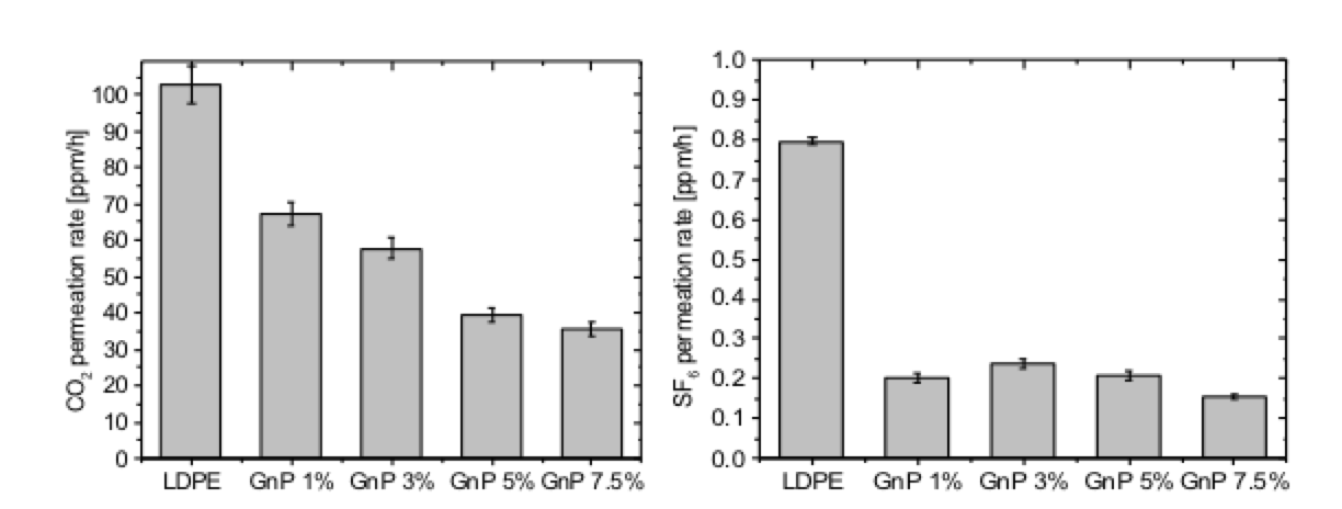
Yet another important property for applications in composite apparatus insulators is permeability to various gases. CO2and SF6 permeation rates were measured for manufactured nanocomposites by monitoring gas concentration in a closed volume of air under atmospheric pressure. At the same time, the gas was supplied from the other side of the specimen under 5 bars pressure. Fig. 5 indicates the impact of adding GnP on permeation rates versus filler content. Permeation rate of CO2decreases gradually with increasing filler content. It drops by 34.7% for a sample filled with 1%wt. of GnP whereas a 65.5% reduction is achieved for the most filled sample (7.5% wt.). Permeation rate for SF6decreased by 74.7% for the sample filled with 1%wt. GnP content and decreased 80.5% for the sample filled with 7.5 %wt. This behavior is related to size of gas molecules.

Materials with Higher Resistance to Bio-Fouling
The impact of biofilm growths (such as combinations of unicellular green algae associated with bacteria and filamentous fungi) on composite insulator withstand has been known for years now. Field observations concluded that such growths are not associated only with tropical or sub-tropical conditions since they have appeared in temperate climates as well. There are several ways a biofilm can influence the structure and function of polymeric materials. These include: bio-fouling (contamination), degradation of leaching components, erosion, hydration, penetration and discoloration. In the case of silicone rubber insulators, the hydrophobic property of their surface can decrease significantly, resulting in higher leakage current, lower flashover withstand and accelerated degradation.
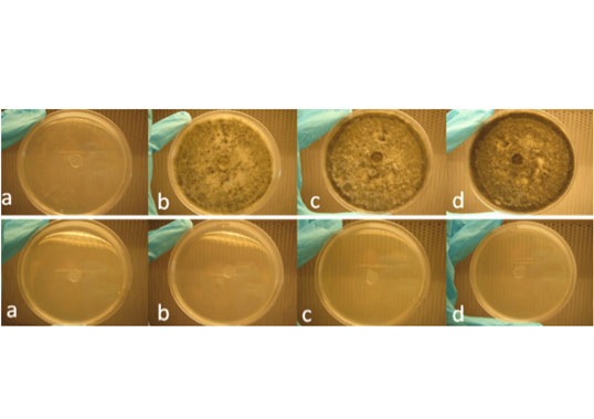
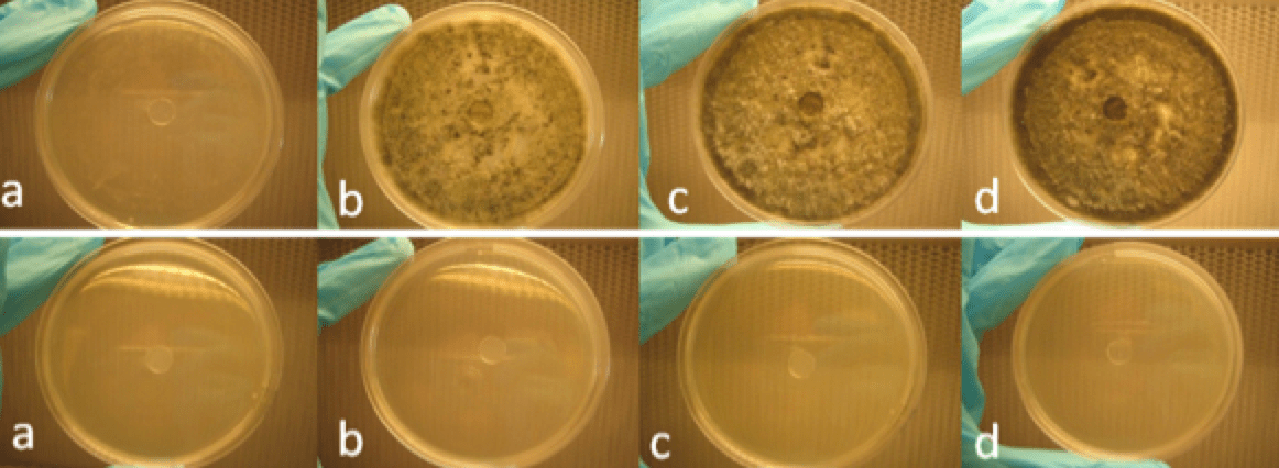
The search for remedies to impede biofilm growth has been ongoing and special additives have been found to make housing materials more resistant to biodegradation. For example, it has been demonstrated that adding the flame retardant, zinc borate, to silicone rubber significantly inhibits biofilm growth. Also, addition of biocides, i.e. active ingredients that kill or inhibit reproduction of micro-organisms, is regarded as another way to improve performance of silicone rubber based materials in environments characterized by increased risk for biofilm. Inclusion of anti-microbial agents, however, must not adversely affect electrical properties of the housing material. One investigation concentrated on evaluating the impact of sodium benzoate and a commercial agent Intercide DCOIT on surface conductivity, volume conductivity and flashover voltage (FOV) withstand of silicone rubber samples. Although the commercial agent appeared more efficient in impeding biofilm growth, it had an adverse impact on the material’s volume conductivity, which may prove undesirable in some applications. Investigations continue and presently focus on more environmentally friendly solutions. For example, recent research at the Royal Institute of Technology in Stockholm showed that biocidal effects in silicone rubber could also be achieved by adding compounds of natural origin, including benzoic acid, thymol, eugenol or chitosan. Thymol appeared to be highly effective against fungal and algal growths and indication of this inhibiting effect is illustrated in Fig. 6. Methods to prevent loss of anti-microbial compounds from the material bulk still need to be developed.
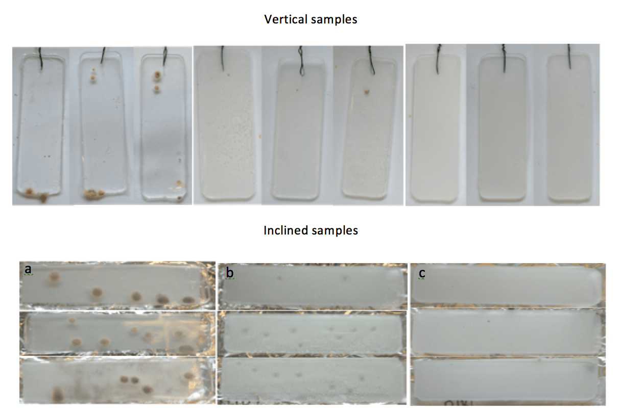
Investigations were also performed that aimed to determine impact of surface texture and roughness on biofilm formation. Patterned and plain silicone rubber surfaces were compared in a humidity chamber, while variation in roughness and improvements to hydrophobicity were achieved by spray-deposition of modified and unmodified ZnO nanoparticles. Insulator geometry was represented by placing the samples vertically and inclined. Microbial growth was not found on the samples characterized by higher surface roughness and improved hydrophobicity whereas the uncoated samples became colonized by micro-organisms (as illustrated in Fig. 7).
Materials with Improved Electrical Strength
Degradation by electrical treeing has been broadly described for cable and epoxy based insulation systems. On the other hand, appearance of this same degradation process in the case of the materials in composite insulators has been comparatively rare, even if demonstrating similar behavior. It is therefore necessary to consider a material’s resistance to electrical treeing whenever designing composite apparatus insulators, where high electrical stress acts radially across the insulator’s walls. Research in Sweden has thus concentrated on mechanisms to improve such resistance in polymeric materials by adding so-called voltage stabilizing agents. A study was performed using polyethylene (LDPE) as the polymer matrix but it is believed that its conclusions can be extended to other polymer systems, including silicones, since the treeing phenomena observed are similar. A newly developed wire-plane electrode test has been adopted for testing electrical tree initiation level in materials containing various types of stabilizers (e.g. benzil, fullerenes, thioxanthone and melamine). The high voltage electrode of the test object (see Fig. 8) is made of electrolytic-cleaned tungsten wire of 10 μm diameter and molded into the tested material. The majority of additives used exhibited positive impact on resistance to electrical treeing, ranging from 20% to more than 100% increased tree initiation field (as shown in Fig. 9). By correlating test results with the electronic properties of these stabilizers it was found that their electron affinity correlates well with stabilizing efficiency. This indicates that electron scavenging is the dominant mechanism behind the improvement.

Materials with Decreased Electrical Conductivity
Another desirable material property, especially for HVDC applications, is very low electrical conductivity. In contrast to pristine polymer systems, which have inherent low conductivity, an approach was adopted based on adding nano-fillers. The study concentrated on investigating their impact on a material’s electrical conductivity. Resistance to electrical treeing was tested as well. LDPE-based nano-composites containing inorganic particles of Al2O3, MgO and ZnO as well as graphene nanoparticles were investigated. Levels of measured current for all nano-composites were significantly lower compared to the reference material, indicating a weakening in charge transport (see Fig. 10). Dependence of electric conductivity of a material, calculated by utilizing charging currents at 4×10⁴ s, on nano-filler content are also illustrated. Similar effects have also been reported by other researchers.
Compared to the pristine polymer, remarkable reduction in electrical conductivity is observed for the nano-composites investigated at a filler content of 3%wt. It appears that this effect is not related to the chemical nature of the nano-filler but rather to formation of polymer-particle interfacial layers. These provide deeper charge trapping sites and reduced long-range molecular mobility.
New Measurement Procedure for Dielectric Characterization of Outdoor Polymeric Materials
All activities focused on developing new materials for power applications have required elaboration of specialized measuring techniques, e.g. to test extremely low electrical conductivity levels or resistance to electrical treeing. In this context, another area of future interest deals with developing methods for dielectric characterization of outdoor polymeric insulating materials. This work has involved co-operation between CIGRE (WG D1.59) and IEC (TC 112 WG 4).
Dielectric measurements can be performed in both time and frequency domains. In the frequency domain, these are known as frequency domain spectroscopy (FDS) measurements and allow extracting the complex impedance of test objects under excitation by voltage signals having variable frequency. One area where FDS is used involves selecting and developing dielectric materials for electrical insulation applications, where precise knowledge of relative permittivity (εr) and dissipation factor (tan δ) are of interest. However, such characterization of materials is often hampered by intricate electrode arrangements since reliable measurements require using electrodes that provide proper contact with test objects. The simplest case is when placing measured specimens between two metal plates. But in most cases specimen surfaces are not ideally smooth and of constant thickness. This means that areas with no direct contact between the electrodes and the surface create current paths along the test specimen that yield a higher loss factor result due to appearance of series resistance in the measurement circuit. Moreover, in the case of specimens made of soft materials, the pressure imposed by the electrode arrangement can lead to their deformation and possibly influence measured permittivity. In addition, series resistance of electrodes and cables can also influence complex permittivity and yield an extra loss peak at higher frequencies that hides the real relaxation mechanism.
Different types of electrode arrangements have been proposed and used to achieve proper material surface contact, each with advantages as well as drawbacks. Among these is deposition of conducting material on the specimen surface, e.g. fired-on metal films, metal or graphite painting, metal sputtering and evaporation, use of conductive glue or grease with metal foils, mercury and water solution of NaCl. All are common solutions but which also introduce additional uncertainty. One robust and simple solution to avoid the contact problem in dielectric response characterization is to entirely avoid direct contact between material and parallel plate metal electrodes. Thus, the combined response of a small air gap and the specimen is measured. Such an electrode arrangement was first introduced in 1906 for capacitance measurements but later abandoned in determining dielectric properties because of accuracy limitations. In addition to the contact problem, geometric influences imposed by the electrode edge effect come into play, thereby distorting electric field distribution in this area.

A way to overcome this problem was recently proposed and today constitutes the subject of internationally coordinated work (i.e. Round Robin Test) by CIGRE WG D1.59, Methods for dielectric characterization of polymeric insulating materials for outdoor applications are being published in the form of a CIGRE Technical Brochure. Fig. 11 illustrates the impact of measuring procedure on determination of material dielectric permittivity using contact-free and contact electrode arrangements in the case of HTV and LSR silicone rubber. For both, the materials tested with the contact electrode arrangement show a clear increase in real permittivity with decreasing testing temperature. Here, thermal expansion of the materials may have influenced the contact measurement but this is not observed for the contact-free measurement.
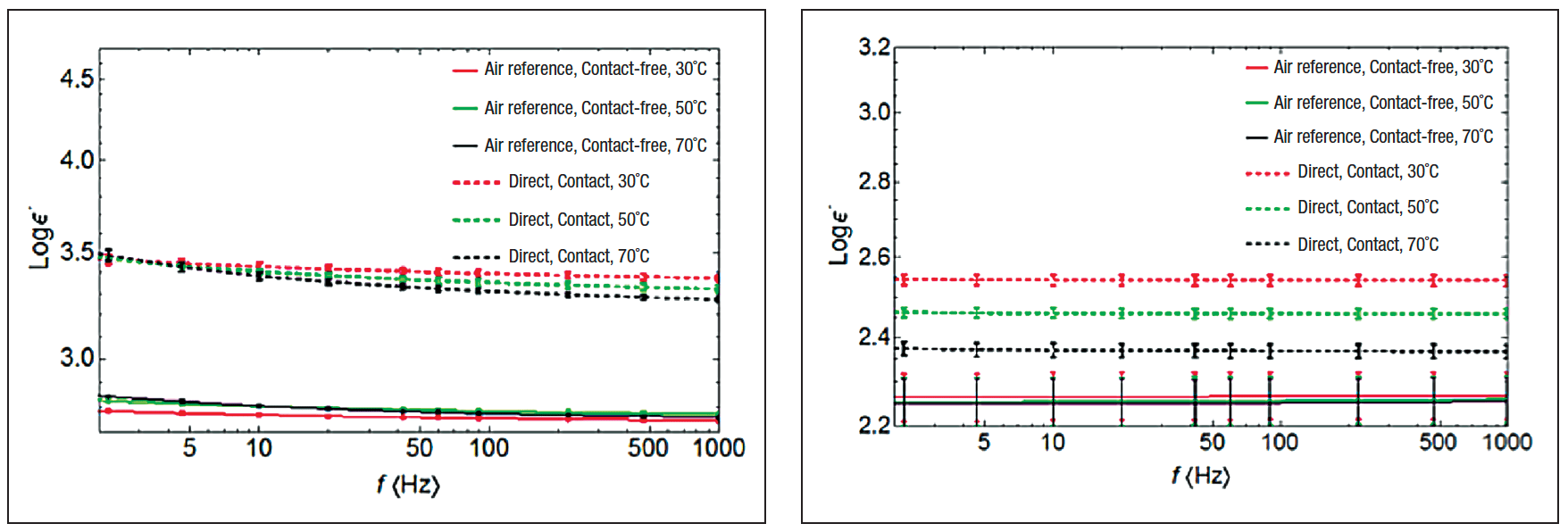
arrangements at frequency range 1-1000 Hz and temperatures 30°C, 50°C and 70°C.
Conclusions
The time needed to develop reliable polymeric insulators and attain broad market acceptance is about 30+ years, based on the experience with current composite insulator technology. Most past research was devoted to searching for reliable materials for line insulators and also toward convincing users that these perform reliably in outdoor environments. In parallel, other work aimed to develop suitable manufacturing technologies, elaborating insulator design criteria and preparing test procedures for the new concepts. Later, came development of polymeric station post and apparatus insulators as well as elastomeric coatings. Together, all these resulted in composite insulation systems now being broadly applied in power engineering.
The aim of future work will be to improve operating performance of polymeric materials, especially for apparatus insulators and cable accessories for HVAC and HVDC applications. Two specific areas are: modifying polymer material properties using additives to enhance field grading, improve resistance to bio-fouling, increase breakdown strength and reduce DC conductivity; and, second, developing suitable test methodologies for more precise characterization of such new materials.