Increasing the transmission capacity of existing lines has become a key topic in the European power supply industry and elsewhere given an open marketplace and steady growth in transfers of electrical energy among EU member countries. This goal is the more pressing since obtaining approvals for new lines is difficult even as new power sources, such as renewable wind generation, require increasing existing power transfer capacities.
The term ‘longitudinal profile’ describes actual clearances from ground and other objects located beneath an overhead line. Based on calculation of different scenarios defined in the standards, such as ice loading, minimum temperature and highest operational temperature, it also reflects security as well as public safety criteria.
Years ago, CEPS, the transmission system operator in the Czech Republic, faced the need to increase the longitudinal profiles of certain overhead transmission lines. The goal was to increase phase-to-earth clearances at critical locations with the ultimate goal of increasing ampacity of these lines.
This edited past contribution to INMR by engineers at CEPS described a solution where upgraded thermal rating was achieved based on increased conductor attachment height.

Decision-Making Process
There are two basic mechanisms to increase capacity of existing power lines, i.e. increasing either thermal rating or voltage rating. Since voltage upgrading is mainly applicable to long transmission lines, thermal uprating was considered the more suitable by CEPS management. In general, increasing thermal rating of lines can be dealt with as follows:
• Re-tensioning conductor
This method is easily applied and there are low material requirements. However, a disadvantage is that re-tensioning conductors which have been in operation for 20 years or more can be risky and a conductor ‘memory effect’ is likely.
• Replacing brackets on lattice steel structures
This method has shown good results and is already widely used on overhead transmission lines in the Czech Republic. However, depending on conductor arrangement, modifying the higher-positioned insulator string becomes necessary because of shortened phase-to-phase distance (see Fig. 1).
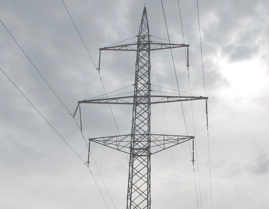
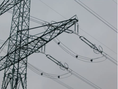
• Modification of insulator strings into special types (upturned V, T)
In most cases, this method requires replacing existing insulators. It is particularly applicable for lines with suspension insulator strings where it has been shown to be most effective (see Fig. 2).
All of the above alternatives are concerned with increasing conductor attachment height and that also means increasing electrical clearances as the basic requirement for system security. Before a final decision was made on which solution to adopt, CEPS engineers reviewed the following factors:
• Condition of existing components on the affected line, especially steel structures and conductors;
• Ready availability of suitable components on the market (including conductors, insulators, etc.);
• Time duration of the power cut on the affected line as well as the estimated cost of the work;
• Ease of access to particular points along the line, i.e. terrain profile, character (forests, agricultural areas, meadows) and ownership of land (public versus private).
Other Considerations
1. Deterioration of components, especially steel structures and conductors, would require their refurbishment. In that case, the selected parameters of the newly-replaced components would match the requirements of the new line profile and there would be no need for special re-engineering.
2. In those cases where there would be a requirement to replace conductors or insulators, new technologies (e.g. conductors with reinforced cores, composite insulators) would make it easier to engineer the best solution.
3. The Czech power grid, based on a network of 400 kV and 220 kV overhead lines, is dense and duration of any outage becomes an important factor in decision-making.
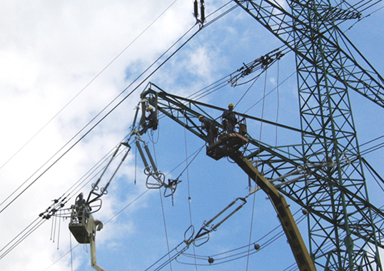
4. In case of good terrain, a machine-operated platform could be used that would make the work easier and save time transporting materials.
The ampacity of existing conductors, according to the original design criteria of the affected line, was based on a maximum operating temperature of 40°C. The subsequent EN standard, however, recommended setting the thermal rating of such lines at 70°C, with a maximum long-term operating temperature of the conductor in most cases being 80°C. The goal was therefore to increase thermal rating of the line to 80°C, meaning a 40°C thermal uprating. After reviewing all above factors, engineers decided on achieving this using the method requiring modification of selected insulator string configurations.
Requirements for Insulators
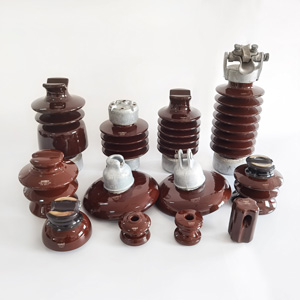
The basic requirements for any new insulator strings were:
1. insulators had to be commercially-available and with no need for customization;
2. weight of the new insulator strings could not exceed that of existing string.
From among the three types of insulators from the dielectric material point of view (i.e. porcelain, toughened glass and composite) the composite design was chosen. Reasons included reduced weight; superior mechanical resistance in the direction perpendicular to the insulator axis; lower acquisition cost; and easier erection procedure.

Testing New Insulator Strings
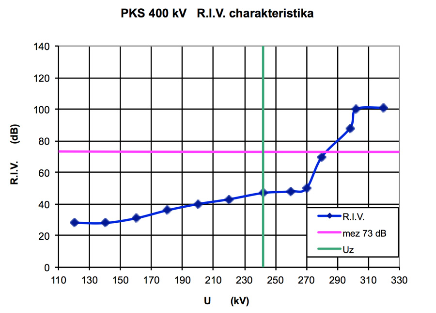
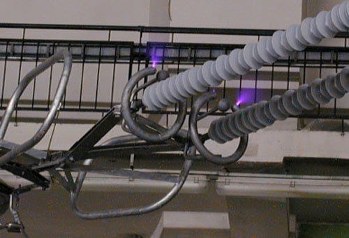
All electrical tests were carried out in accordance with IEC and EN requirements. There was no need for mechanical testing. Electrical testing included: a power arc test; a wet switching impulse test; a dry lightning impulse test; and testing for any radio interference voltage (RIV). The result of RIV characteristics for the insulators selected is shown in Fig. 3. The value at 242 kV was lower then 73 dB, in accordance with EN 61000-6-4:2002. Corona testing was then performed to confirm that any corona occurred only at the grading rings.

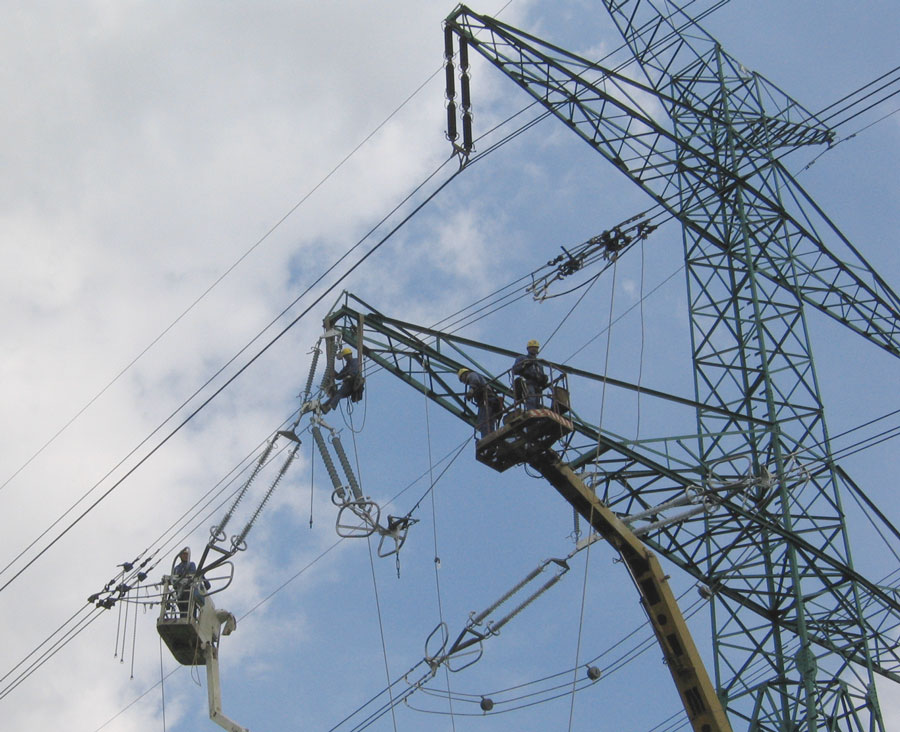
Application of Methodology
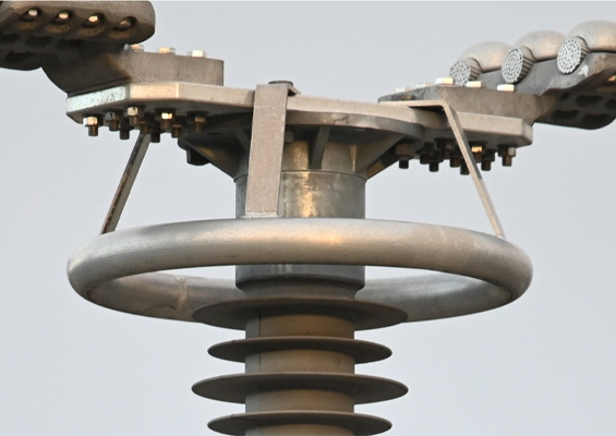
A double circuit 400 kV line, which was one of the recent applications for such a thermal uprating, crossed a dry area with barriers against periodic flooding. Because of this, the longitudinal profile (clearances) had to be increased to fulfil the requirement of system security whenever the maximum level of such flooding would occur. The project involved replacing former ceramic double insulator string having total length of 4982 mm. The new insulator string, in the shape of an ‘upturned T’, was installed having a total vertical length of 1927 mm. This resulted in increasing phase-to-earth distance by 3055 mm, which enabled increasing thermal rating of the line’s conductor to 80°C.
Replacing each affected insulator string took about half a day. For an average span of 300 m, the line’s thermal rating depends on clearances according to the following calculations:
T+1°C = D + 0.03 m
D+1°C = I + 30 A
where T = thermal rating
D = distance in the middle of span (i.e. clearance from the ground)
I = current rating of three-bundled conductors
The first relationship shows that increasing thermal rating by each 1°C requires shortening conductor attachment height by 3 cm. The second relation demonstrates that thermal uprating by 1°C results in possible higher conductor rating of 30 Amps.

Conclusions
The main advantages of this retro-fit process were:
• Excellent methodology for thermal uprating of a line;
• Relatively short shut-down time for the affected line since only about half a day was required for each affected insulator string.
On the negative side, however, existing conductors have to be cut and, in the event of a failure, the new shorter suspension string represented a higher load for the brackets of the structure in the axial direction.