Polymeric insulators have achieved technical maturity due to adapting to lessons from growing service experience as well as continuous refinements in applicable IEC standards. Moreover, over the past decades there has been a rapid transition from an era when these insulators were regarded as exclusive and costly to the present market situation where they are considered ‘commodities’. The relative speed of this transition has been attributed to the large body of application knowledge as well as more automated production and related economies of scale that helped reduce costs.
At the same time, there have been reports of negative service experience and corresponding calls to update and further improve existing standards. For example, one of the most important design aspects for these insulators is the longitudinal interface between the core rod and the polymeric housing. Indeed, failures at this interface have been one of most critical aspects leading to end-of-life situations. Based on this, questions have been raised whether present standards and the procedures used to test interface design are sufficiently sensitive and whether any design test result can ever be transferred to routine test behavior.
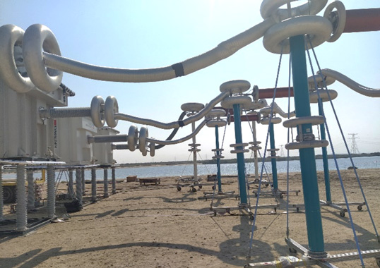
This edited past contribution to INMR by experts at EGU HV Laboratory, Pfisterer Switzerland and ČEPS presented findings from laboratory investigation into failures of polymer insulators at the critical core-housing interface.
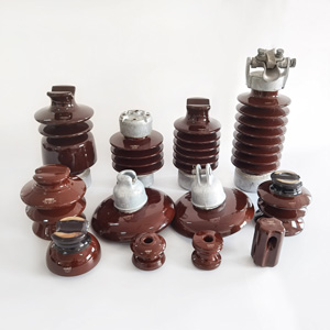


Polymeric insulators have been used worldwide on overhead lines and for other applications for decades, predominantly for AC but also in several DC applications. Choice and development of suitable material compositions and methods of manufacture have improved significantly since the first generation. Nonetheless, the basic design principle has not changed in the terms of how the technical requirements are shared among the different elements and materials used in this construction. Apart from avoiding premature ageing of the housing, it has also become evident that it is critical to protect the fiberglass reinforced (FRP) rod and its interface with housing against moisture. This will prevent failure by insulator puncture (also called ‘flashunder’), which can result in complete mechanical disintegration and dropped conductor.
Based on this, it is now clear that reliable long-term performance can only be achieved if a polymeric insulator is designed to have:
• a consistently reliable and high-quality manufacturing process;
• adequate design that reflects its service conditions;
• appropriate choice of housing material to match service and environmental conditions; and
• functional, reproducible quality of interfaces in terms of long-term adhesion.

Service Experience & Laboratory Testing
Service experience has confirmed that poor adhesion along the rod-housing interface is a key trigger for development of internal tracking. This will eventually result in insulator puncture should the tracking path achieve sufficient length that the remaining unaffected length can no longer withstand an overvoltage or even line-to-ground voltage. This conclusion has only been reinforced by years of experience with failures during design testing of polymeric insulators. For example, years of laboratory testing have revealed that about 10% of polymeric insulators fail during design and type testing. Fig. 1 shows how these failures have been distributed among the different design tests.
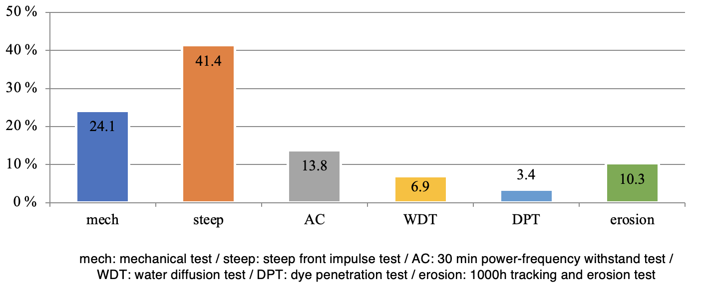
As evident, insulators fail mainly during interface testing either by a steep-front impulse test (41%) or by the 30-minute power frequency withstand test (14%), i.e. 55% of all types of insulator failure under laboratory testing conditions relate to this interface. Moreover, insulator samples that failed during the water diffusion test also indicate poor housing-to-rod bonding rather than low rod quality. That means up to 60% of the polymeric insulators being tested under laboratory conditions fail due to issues with interface quality. Clearly, based on service and testing experience, bonding quality represents the major determinant with respect to failure of polymeric type insulators.
Special Water Absorption Test Sequence
Laboratory studies were conducted with the goal of setting up a special test sequence. This sequence included pre-stressing to simulate water absorption in an accelerated manner through the bulk of a polymeric housing material as well as moisture propagation in the interfaces, i.e. along an FRP rod with areas of poor or no housing-to-rod bonding.
The special thermal cycling water absorption test sequence consisted of the following:
• Tap water was used and heated in a vessel to approx. 54°C;
• Temperature was kept at that level for one hour;
• Water was cooled to room temperature (approx. 24°C), i.e., one thermal cycle consisted of a heating phase and a cooling phase with total duration 8 to 9 hours;
• Cycles were continuously repeated for a specific period;
• Finally, a 30-minute AC withstand voltage test acc. to IEC 62217 was conducted with temperature of the insulator shank of each sample monitored using an infrared camera. Maximum temperature change was recorded.
The main goal was to compare behavior of insulator samples under specific pre-stress conditions under different numbers of thermal cycles in water. This would simulate moisture absorption phenomena through the housing materials and along FRP rod-to-housing interfaces. The different test objects included special test samples, insulator samples from among those provided for regular design testing and samples removed from service. All insulators tested were manufactured with silicone rubber housing material, either high-temperature vulcanizing (HTV) silicone or liquid silicone rubber (LSR).
1. Insulator Samples with HTV & LSR Housing Materials: Case Study 1
Special polymeric long-rod insulator samples with HTV silicone housings were made for testing purposes to simulate different qualities of housing-to-rod bonding. The samples tested either had no chemical bonding or 100% chemical bonding.
Next, two LSR long-rod insulator samples made for the purpose of design testing were also included in the test scenarios. Those samples were expected to have little to no housing-to-rod adhesion based on experience with previous samples from that same production batch. None of these samples had earlier been subjected to any design or type testing.
The following test procedure was applied to all samples:
• Initial testing done acc. to IEC 62217: Test samples were boiled for 42 hrs. Then, the steep-front impulse test was conducted. The 30-minute AC withstand test was also performed on samples with temperature measurements before and after the test;
• A ‘rest’ period of one month to allow moisture to evaporate from the silicone housings;
• A special thermal cycling water absorption test sequence, i.e. after application of different numbers of thermal cycles (e.g. 65, 96, 121) samples were removed from the vessel and subjected to steep-front impulse testing as well as the AC withstand test with measurement of temperature;
• Peel testing was done on selected samples.
Table 1 summarizes test results.
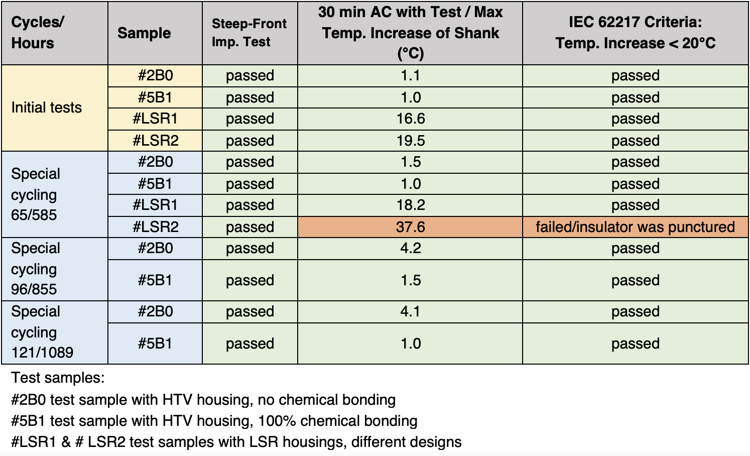
All samples passed initial testing. Those samples with LSR housings (expected to have little or only poor bonding) showed higher temperature rises after the initial 30-minute AC withstand test (i.e. 16.6°C and 19.5°C). Nonetheless, all samples still passed criteria given in IEC 62217 in regard to interface testing.
The temperature rise in the LSR samples also increased during application of the water absorption test procedure. Then, sample #LSR2 failed the AC withstand test due to internal puncture. Temperature rise was above 37°C.
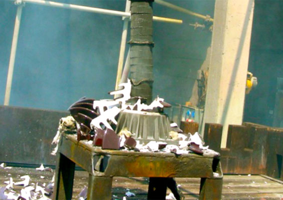
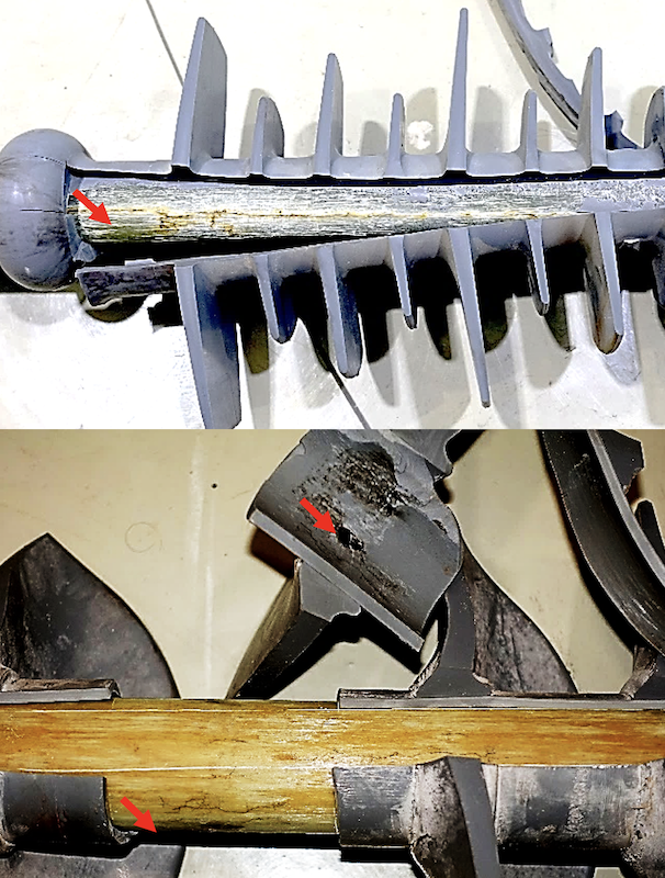
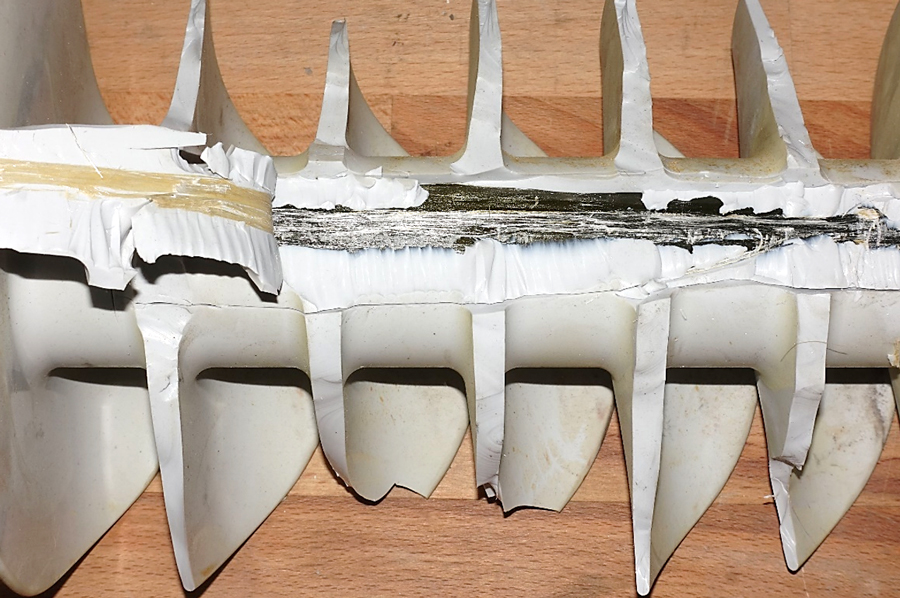
A peel test was performed on samples #LSR1 and #LSR2 after 65 thermal cycles of water absorption and after the AC withstand test. As expected, no bonding was observed on either sample. Moreover, after internal flashover, sample #LSR1 showed carbonized tracks along the rod-to-housing interface due to lack of bonding. Sample #LSR2 also showed carbonized tracks due to internal electrical discharges during the AC withstand voltage test (see Fig. 2).
Samples #2B0 (i.e. with no chemical bonding) and #5B1 (with 100% chemical bonding) both passed all tests. But sample #2B0 showed a slightly higher temperature rise after application of several thermal cycles of the water absorption procedure. Clearly, more time was needed for moisture ingress to reach the FRP rod through the bulk of the HTV housing material.

2. Insulator Samples with HTV & LSR Housing Materials: Case Study 2
Special samples with HTV housing and without any chemical bonding between rod and housing were used. Moreover, these samples were manufactured either with or without chemical sealing at the triple point, i.e. sample #92B0 was made with chemical sealing at the triple point while sample #93B0 was made without chemical sealing at that point (see Fig. 3).
The samples with LSR housing were from among those supplied by a customer for standard design testing for product qualification according to IEC 61109 and IEC 62217. Table 2 summarizes test results.
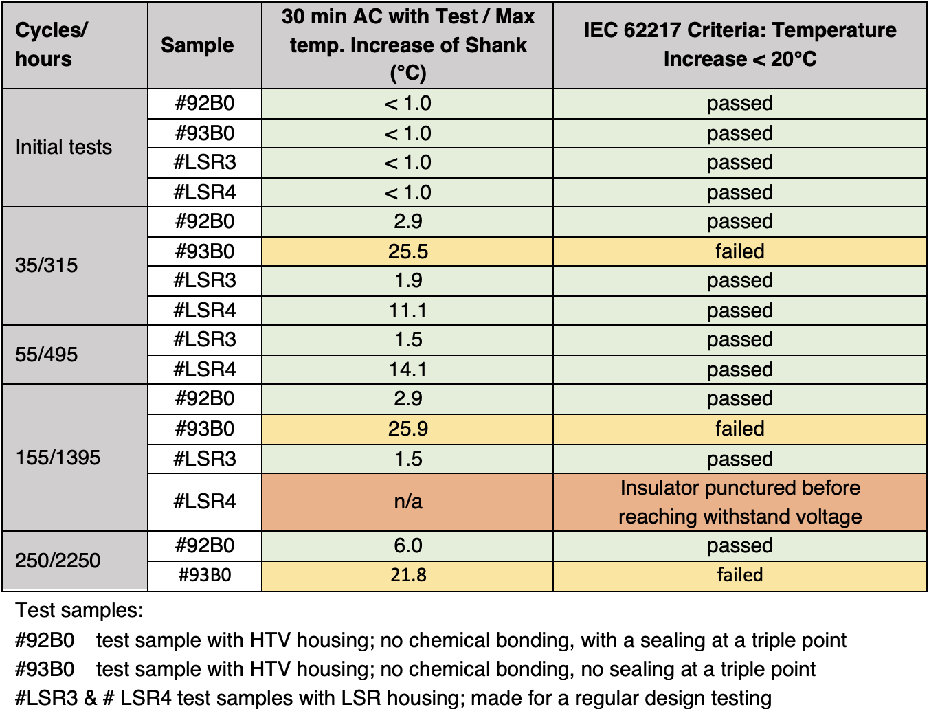
Fig. 3 shows special insulator samples with HTV housings after 250 of thermal cycles.
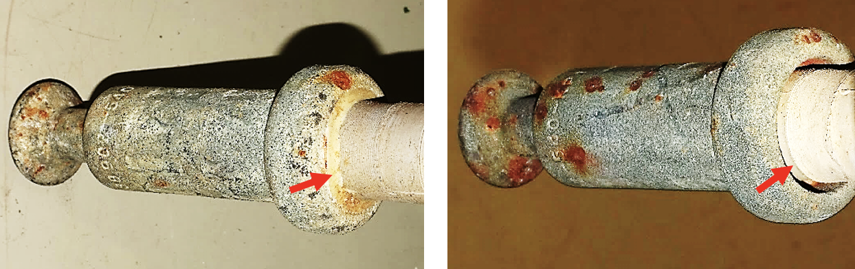
Different behavior was observed for insulator samples with LSR housing and HTV housing materials with respect to rate of moisture ingress and propagation along their rod-to-housing interfaces. For example, the test sample with HTV housing, no bonding but with sealing at the triple point (#92B0) showed no notable temperature increase at the shank and passed all criteria given in IEC 62217 at each stage of testing (see Fig. 4). Obviously, the mechanical bond between FRP core rod and housing created by the housing’s shrinkage during the curing process was sufficiently strong to prevent moisture propagation along the FRP rod-to-housing interface
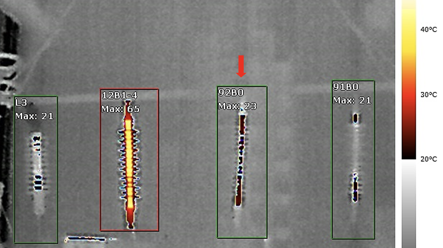
The sample with HTV housing, no bonding and with no sealing at the triple point (#93B0) recorded a high temperature rise at the shank and failed the criteria in IEC 62217 at each stage of testing (see Fig. 5). This was due to lack of sealing and likely weaker mechanical adhesion of the housing to the FRP rod.
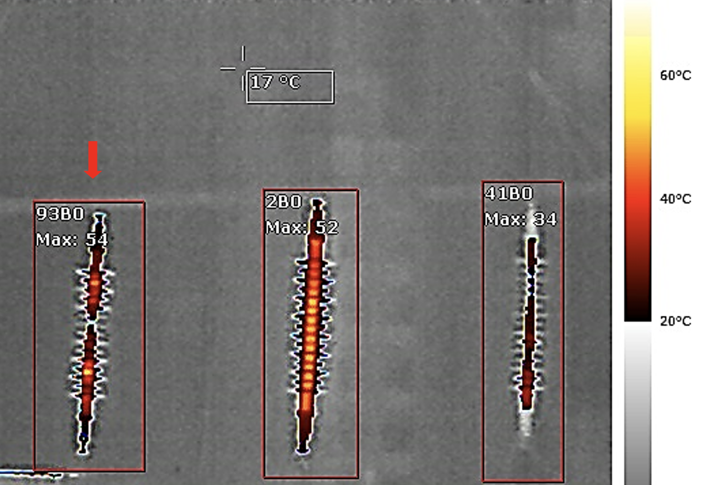
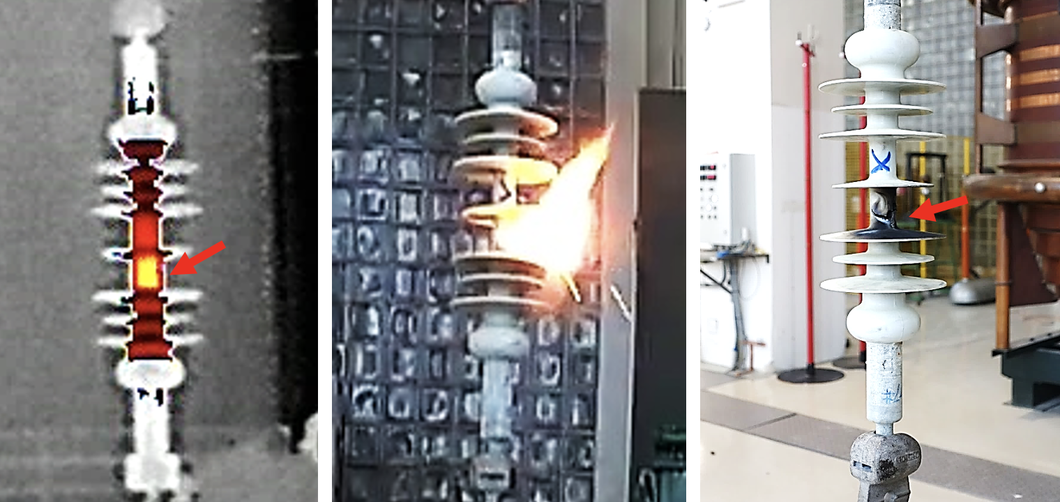
Sample #LSR4 (with LSR housing) recorded a temperature increase of more than 10°C after 35 thermal cycles (312 hours) and 55 thermal cycles (492 hours) but still passed the criteria in IEC 62217, meaning Δt < 20 K. Subsequently, it punctured after 155 thermal cycles (1395 hours) and a critical hot spot was localized at its middle (see Fig. 6).
Peel testing was subsequently conducted on intact sample #LSR3 and showed good chemical bonding between rod and housing (see Fig. 7).
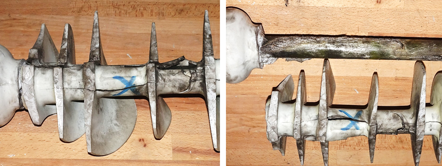
Peel testing on sample #LSR4 showed virtually no chemical or mechanical bonding of the housing to the FRP rod (see Fig. 8).

Summary of Case Studies 1 & 2
A special water absorption test method was used to investigate quality of the FRP rod-to-housing chemical bond in polymeric insulators. Different behavior was observed for samples with LSR housing and HTV housing materials with respect to rate of moisture ingress and propagation along the rod-housing interface.
Samples with LSR housing and poor or no bonding failed by puncture after 155 thermal cycles (1395 hours). Most significant was that samples with no bonding still passed the criteria in IEC 62217 (and also IEEE C29.11) which specify that maximum temperature rise of the housing surface must be below 20°C (K). That value is clearly too high and does not guarantee samples without sufficient chemical or mechanical bonding will be detected during testing. By contrast, samples with good bonding showed only minor temperature rise at the housing surface i.e. no moisture propagation along the interface could happen.
Test samples with an HTV housing, no bonding but with sealing at the triple point showed no notable temperature increase of the shank and passed criteria given in IEC 62217 at each stage of testing. But samples with HTV housing, no bonding and with no sealing at the triple point showed a high temperature rise of the shank and failed criteria in IEC 62217 at each stage of testing. This was due to lack of sealing and probably weaker mechanical adhesion of the housing to the FRP rod.
It is noteworthy that samples with HTV housings and no chemical bonding (i.e. no primer applied) showed much better adhesion to the rod than samples with LSR housing and no bonding. Apart from different water absorption behavior, this may also relate to different processing and curing conditions. Whereas HTV silicone rubbers are usually cured at temperatures of about 160 to 180°C, they experience higher thermal shrinkage than LSR rubbers which are usually cured at 100 to 120°C. As such, higher mechanical pressure to the FRP rod can be achieved for HTV samples, which helps reduce risk of water accumulation at the interface. Fig. 9 shows HTV samples with and without chemical bonding after peel testing. Even without applied primer, test samples still showed high mechanical adhesion to the rod, which would result in high tear strength and low leakage currents during the water diffusion test.
3. Performance of Samples with HTV Housing from Service: Case Study 3
Several long-rod polymeric insulators exhibiting some deterioration in their housing surface were removed from a 400 kV line after 8 to 10 years in service and two full-scale insulator samples were taken for testing. Three test specimens were then cut from each sample representing a top part (i.e. grounded side in service), a middle part and a bottom part (i.e. energized in service).
Test specimens were subjected to:
• Modified test on interfaces according to IEC 62217 with specimens boiled for 100 hours, followed by the 30-minute AC withstand test with surface temperature monitored by an IR camera;
• Rest period of one month to allow moisture evaporation from the silicone housing;
• Special water absorption test sequence (8 cycles / 72 hours), followed by the 30-minute AC withstand test with surface temperature monitored using an IR camera.
The same test specimens were used for these test procedures. Table 3 summarizes findings.
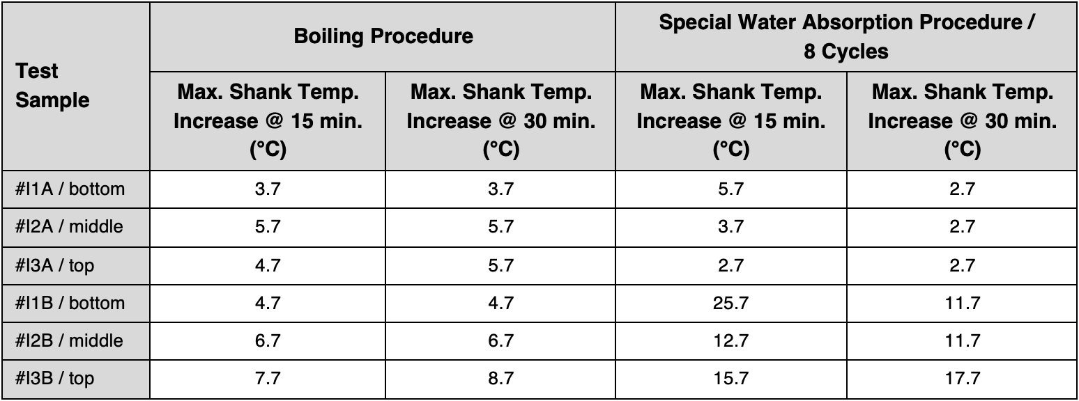
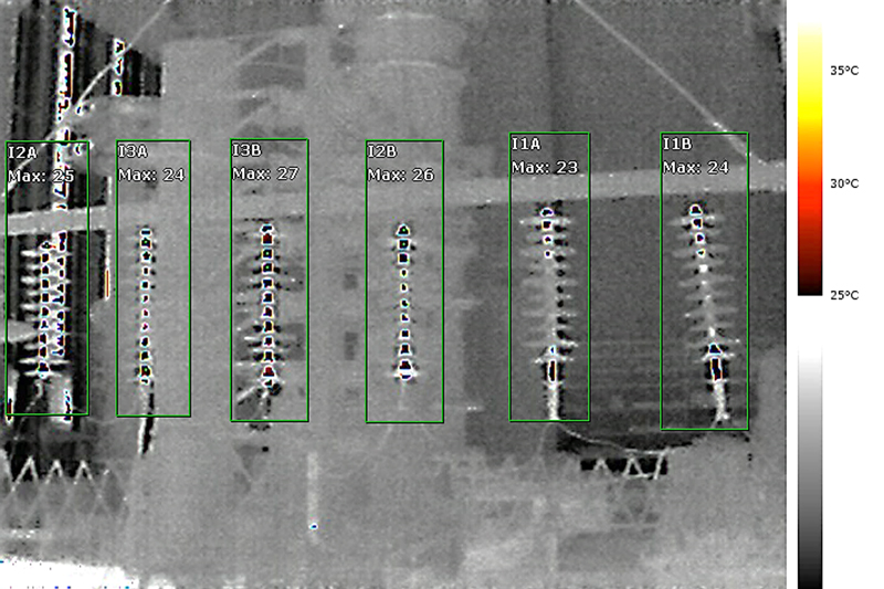
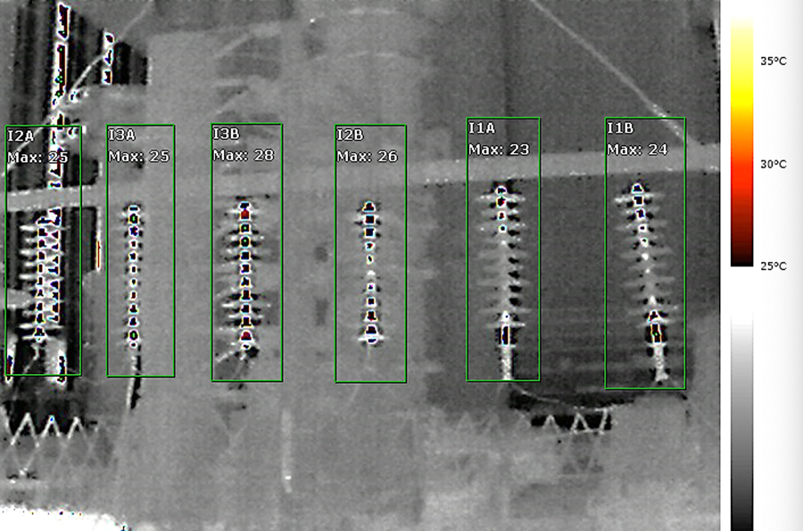
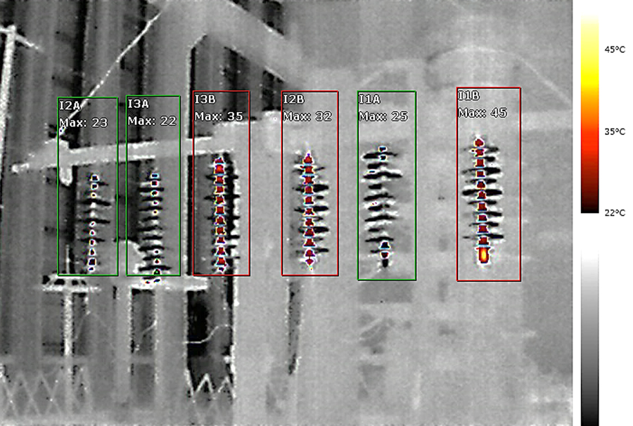
Figs. 10, 11, 12, 13 show thermal images of the samples after the boiling procedure and special water absorption pre-stressing (8 cycles) at 15 minutes and 30 minutes of AC withstand testing.
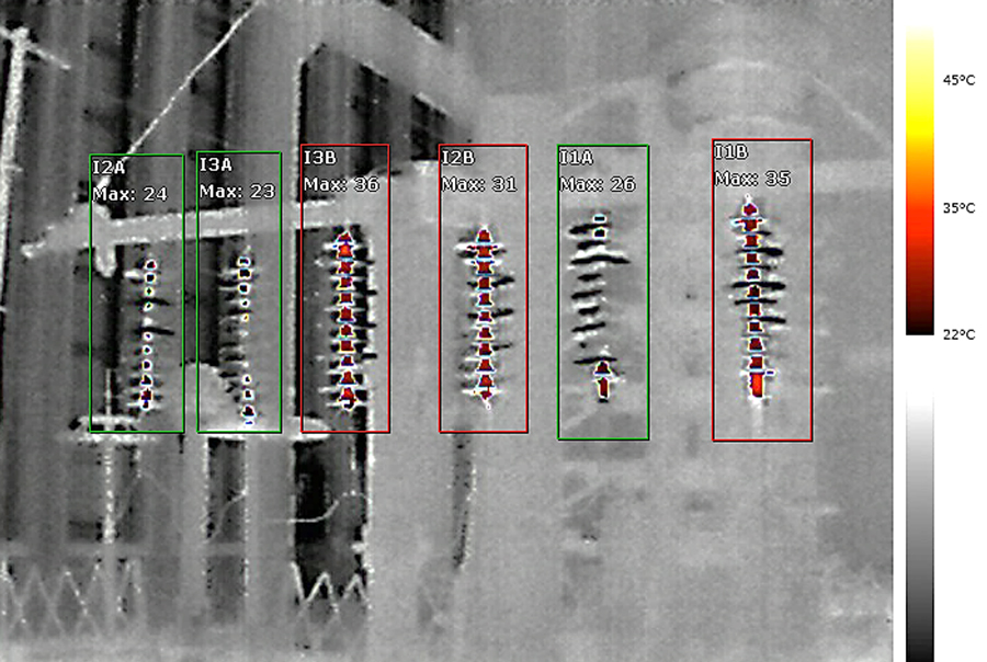
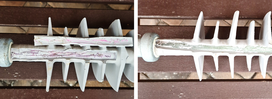
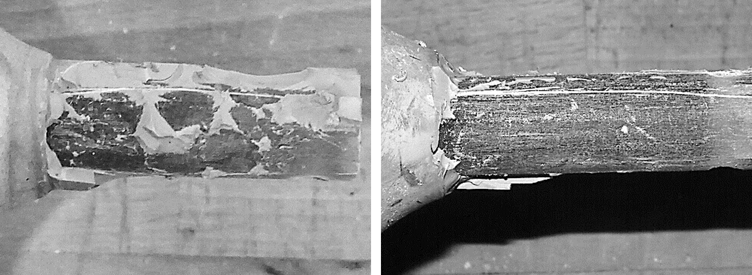
Peel testing at the top parts of samples #I1A & #I1B was conducted to check level of adhesion of the silicone housing to the fiberglass core (see Fig. 14).
Summary of Case Study 3

Investigation of insulators removed from service revealed the following:
• Maximum temperature increase of shanks was below 10°C (K) with regard to the modified test on interfaces according to IEC 62217 with boiling procedure applied. i.e. samples passed testing;
• Maximum temperature increase does not vary, comparing measurements at 15 and 30 minutes of AC withstand testing;
• Maximum temperature increase of the shanks was below 10 K in regard to the modified test on interfaces according to IEC 62217 with boiling procedure applied. i.e., samples passed testing.
• Maximum temperature increase of the shank of sample #I1B was higher than 25°C (K) when applying the special water absorption procedure (8 cycles). i.e., samples failed evaluation criteria according to IEC 62217;
• Maximum temperature increase varies if comparing measurements done at 15 minutes (45°C) and 30 min (35°C) of AC withstand testing;
• Peel testing showed reduced level of adhesion of housing to core for sample #I1A. For sample #I1B, almost no adhesion between housing and core was detected.
Long-Term Water Absorption Stressing of Insulator Samples with HTV Material
Long-term behavior was also studied of samples with HTV housings under specific pre-stressing conditions. Samples #1B0 and #2B0, without chemical bonding between FRP rod and housing, were subjected to long-term thermal cycling water absorption testing. Table 4 summarizes maximum temperatures recorded during 30-minute withstand voltage testing after different numbers of cycles.
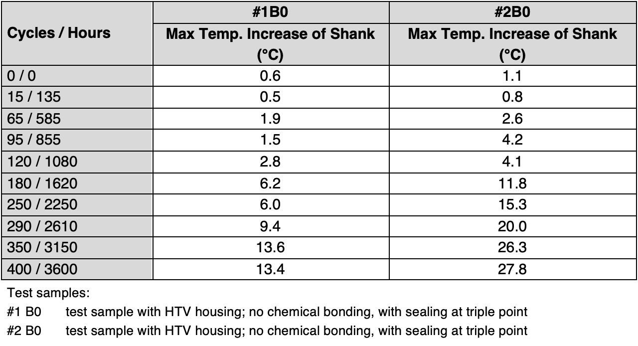
Fig. 15 charts maximum temperature rise of the housing surfaces of samples #1B0 and #2B0 during 30-minute withstand voltage test after particular numbers of thermal cycles.
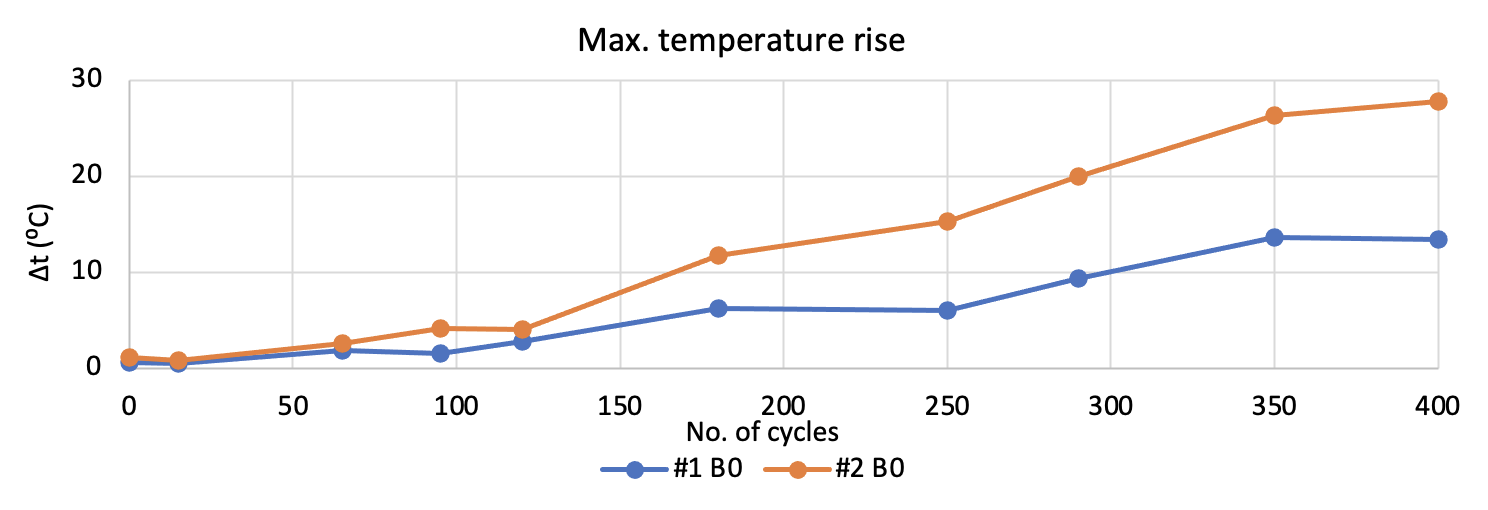
Samples showed a temperature increase in their housing surface over time (i.e. with increasing number of applied thermal cycles) that was proportional to the amount of moisture that had penetrated through the silicone material.
Sample #1B0 showed much slower moisture propagation along the housing-to-rod interface than did sample #2B0, probably due to a different level of mechanical adhesion of the housing to the rod. Peel testing was not carried out since samples were to be used for further water absorption testing.
Conclusions
A special thermal cycling water absorption test sequence was investigated to verify the quality of housing-to-rod bonding in polymeric insulators. Different behavior was observed for insulator samples with LSR and HTV housing materials with respect to rate of moisture ingress and propagation along the rod-housing interface.
Samples with LSR housings and poor to no bonding failed by puncture after a certain number of thermal cycles applied. Given this, criteria specifying a maximum temperature rise of housing surface to be below 20° K, as per IEC 62217 and other standards, is too high and does not guarantee that samples with insufficient chemical and mechanical bonding will be detected.
HTV housed samples with no bonding but with sealing at the triple point showed no notable temperature increase of the shank and passed criteria given in IEC 62217 at each stage of testing. This was because the mechanical bond between FRP core rod and housing due to housing shrinkage during curing was strong enough to prevent moisture propagation along the rod-housing interface. By contrast, HTV housed samples with no bonding and with no sealing at the triple point showed a high temperature rise of the shank and failed the criteria in IEC 62217 at each stage of testing. This was likely due to lack of sealing and probably weaker mechanical adhesion of the housing to the rod.
Polymeric long-rod insulator samples with HTV housing taken from service passed the modified interface testing with the boiling procedure involved. But samples with poor bonding failed AC withstand testing after the special thermal cycling water absorption procedure.
Differences in quality of bonding of samples with HTV and LSR housing must also be taken into account in view of the different silicone material formulations and manufacturing processes used in industry. HTV materials are usually cured at temperatures of approximately 160 to 180°C and therefore a higher thermal shrinkage to the rod.
A 30-minute AC withstand test with temperature monitoring according to IEC 62217 is a highly useful test method. While leakage current measurements did not show high sensitivity, an improved test circuit with separate resistive and capacitive parts of leakage current would help.
Simulating the failure mechanism of in-service polymeric insulators having no or very poor bonding is difficult since this takes place over a long-term when insulators are energized. Regarding insulators with HTV silicone housing materials, longer water absorption pre-stressing might be needed to reach an adequate moisture ingress level such as to seriously affect electrical performance.
The special thermal cycling water absorption procedure using tap water is more severe than the boiling procedure given in IEC 62217. This is because this procedure enhances capability for water to penetrate through the bulk of the silicone material due to its lower specific conductivity and relative permittivity. In the case of a high temperature increase on the insulator shank, i.e., high real current flowing through the housing-rod interface, moisture evaporation starts about 15 minutes after AC withstand testing. This might result in reduction of the shank’s temperature in the testing interval between 15 and 30 minutes.
As such, when evaluating quality of bonding of a housing to the FRP rod, it is important to consider polymeric material type and properties, chemical bonding and also mechanical bonding. Future work will concentrate on further studies of moisture ingress phenomena through silicone housing materials as well as through the triple point when there is improper sealing. Quantification of thermal changes, related to real current flow through an insulator, will also be studied in more detail.
Better understanding different possible levels of bonding quality for polymeric insulator interfaces will help improve evaluation of present condition as well as predicting future service performance. IEC 62217 is currently under revision.
References
[1] IEC 62217:2012 Polymeric HV insulators for indoor and outdoor use – General definitions, test methods and acceptance criteria.
[2] Lachman, J.: “Lessons from 25 Years’ Experience Testing Polymeric Insulators” INMR World Congress 2019, Tucson, USA.
[3] Baer, C., Schmuck F., Strumbelj, J. Tinner, E., Lachman, J., Kornhuber S., LOH, J. T.: “Technical Demands to Improve Today`s Polymeric Insulator Reliability” Cigre General Session 2020, 2021 and 2022, Paris, France.