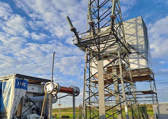
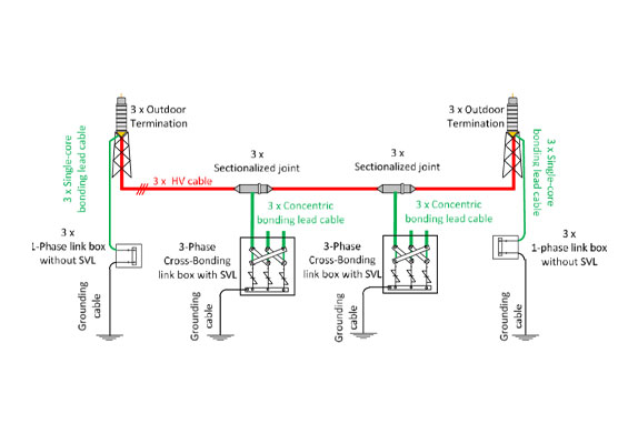
Sheath voltage limiters (SVLs) are used in long underground cable systems, when sectionalized cross-bonding is applied for the sheath bonding design. The sheath voltage limiters provide protection to the sheath bonding system against transient overvoltages and their selection is part of the insulation coordination process. Typically, two main parameters are considered in the selection process of the SVLs, a) the continuous operating voltage, Uc, and b) the protection level, Upl.
This edited contribution to INMR by Kostas Velitsikakis and A. Kumar at TenneT TSO focuses on selection of sheath voltage limiters when considering charge transfer capability. Their electromagnetic transient analysis is the result of root-cause analysis regarding a failed cross-bonding joint of an underground cable system in a 380 kV Siphon Circuit in the Dutch EHV grid. The study considered circuit energization and evaluated overvoltages across the sheath interruption of cable joints as well as energy dissipation and charge transfer levels of the SVLs.


In general, a cable system can be subjected to transient overvoltages resulting from:
a) switching actions, e.g., energization of the circuit, fault inception within the circuit and its subsequent clearance; and
b) fast-front overvoltages due to lightning strikes on nearby overhead lines.
Such overvoltages can stress the cable’s main insulation as well as the insulation of the sheath bonding system as well as accessories. Unless properly mitigated, such overvoltages could exceed the specified insulation withstand levels, leading either to a reduced lifetime of a component or to insulation degradation, potential dielectric failures and long repair times.
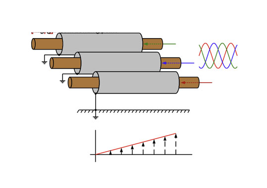
Long underground cable circuits have become more common in the Dutch transmission grid due to increasing number of HV and EHV expansion projects. Sectionalized cross-bonding has been the standardized sheath bonding design applied (as illustrated in Fig. 1).
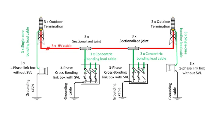
International standards provide guidelines for selection of minimum sheath insulation withstand levels with respect to bonding lead lengths. However, there are few detailed guidelines for proper insulation co-ordination of a sheath bonding system. For maximum bonding lead lengths or for selection of sheath voltage limiters, no distinction is made with respect to nominal voltage of a cable system or if it is part of a Siphon circuit.
Below, focus is placed on the SVL selection when considering the charge transfer capability and its importance in the insulation coordination process to achieve a sufficient performance against transient overvoltages. Main findings and lessons learned are presented based on results of a cable cross-bonding joint failure investigation and root-cause analysis.

Description of Cable System & Failure Event
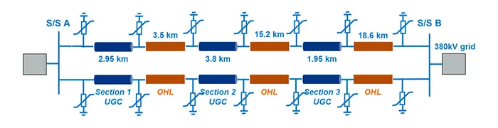
TenneT is the Transmission System Operator in the Netherlands and and also a part in Germany. The Dutch EHV grid operates at a nominal voltage of 380 kV and consists mainly of overhead line circuits. Nevertheless, in the western part of the grid, the so-called Randstad380 System is in operation, i.e. circuit connections consist of overhead line parts in combination with multiple and relatively long underground sections. The system under study, commissioned in 2018 and put into operation in 2020, refers to a double circuit connection between the two 380 kV substations A and B (see Fig. 2) and total circuit length is approximately 46 km.
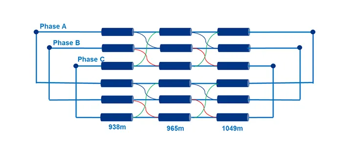
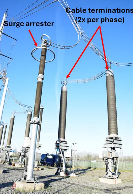
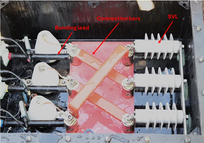
Each circuit consists of three underground cable and three overhead line sections respectively. Due to transport capacity requirements, two cables per phase (Figs. 3 and 4) are applied that result in a total cable length of approximately 105 km. Sectionalized cross-bonding is applied with the following characteristics per cable section: one major section per cable system, 3 minor sections per cable system, 6 cross-bonding joints per cable system, 2 link boxes per cable system and each one equipped with 3 sheath voltage limiters (Fig. 5). Single-core cables are used as bonding leads, with length estimated at 20 m.
Table 1 summarizes the main information of the cable systems within the cable section 1 of the circuit. Table 2 provides the main data of the SVLs and of the surge arresters that are present at both transition ends of each cable section.



Failure Event
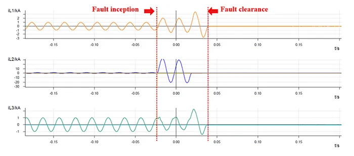
In Jan. 2023, one of the outdoor cable terminations failed at the transition point between the underground cable Section 1 and the overhead line. The failure resulted in a single phase-ground fault, which was correctly cleared within 70 ms by the differential protection of the cable system, as shown in the protection recordings of Fig. 6. Because the fault was detected within the protection zone of the cable section, the single-phase auto-reclosure function was blocked and the complete circuit was de-energized. The root-cause analysis concluded that the cable termination failed mechanically and no link was made to possible dielectric stresses due to transient overvoltages.
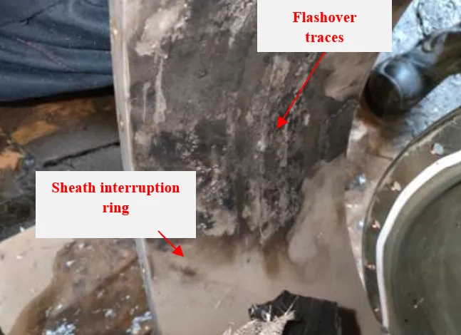
Nevertheless, following the repair, an HVDC voltage test was conducted to check the integrity of the cable sheath. During the test, an abnormally low resistance was detected at the sheath interruption of one of the six cross-bonding joints at the end of the first minor section as seen from S/S A. The laboratory investigations indicated traces of severe electrical activity on the sheath interruption ring, as shown in Fig. 7. Moreover, the System Operations data showed that both Siphon circuits are frequently switched, as an alternative measure to control the system voltages below the maximum allowable voltage of 418 kV, as specified in the Dutch grid code.
Based on the above findings and information, transient overvoltages were considered as possible root-cause of the cable joint failure. An electromagnetic transient (EMT) analysis was therefore conducted to evaluate performance of the insulation coordination of the sheath bonding system by analysing:
a. transient overvoltages at cross-bonding joint locations;
b. energy dissipation and charge transfer levels in the SVLs;
c. impact of bonding lead length on the resulting overvoltages;
d. impact of SVL selection on the charge transfer.
The EMT analysis focused on switching transients due to circuit energization.

EMT Analysis
For the purpose of the transient analysis, an EMT model was developed in EMTP-ATP. The model included detailed representation of the main components of the Siphon circuits (overhead line sections, surge arresters, underground cable sections, bonding leads and SVLs) and was extended several nodes further than Substations A and B to account for simulation of slow-front overvoltages due to switching events.
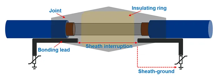
The transient simulations calculated the sheath-ground and sheath-sheath overvoltages at the sheath interruption points of Cable Section 1 of the circuit (as shown in Fig. 8). Moreover, energy dissipation and charge transfer of the sheath voltage limiters were monitored. Calculated values were evaluated against given lightning insulation withstand levels (LIWL) and SVL data sheet values (as summarized respectively in Tables 2 and 3).

Parametric Switching Analysis
A parametric switching analysis was conducted, by varying the energization instant in steps of 1 ms within half a cycle of the power frequency voltage waveshape. The analysis considered the simulation cases, as listed below:
• Case 1: Circuit energization from S/S A, i.e. circuit breaker at S/S A closes and circuit breaker at S/S B remains open.
• Case 2: Circuit energization from S/S B, i.e. circuit breaker at S/S A remains open and circuit breaker at S/S B closes.
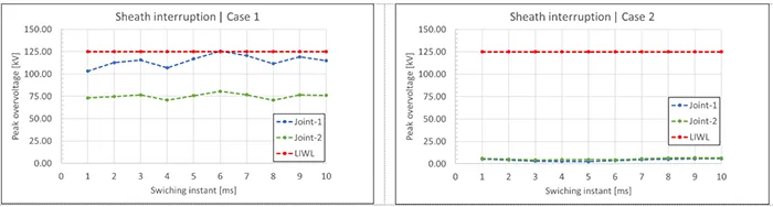
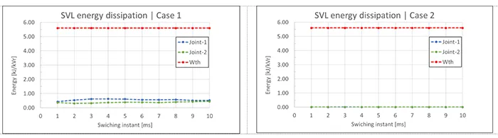
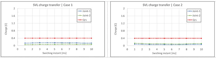
In Case 1, the resulting peak overvoltages across the sheath interruption of the cross-bonding joint 1 are close to or slightly higher than the specified LIWL for all switching instances (Fig. 9). On the other hand, Case 2 results in significantly lower peak overvoltages. Although in both cases calculated energy dissipation levels remain well below given thermal energy withstand of the SVLs (see Fig. 10), Case 1 (irrespectively of switching instant) results in much higher charge transfer levels at both measurement locations (see Fig. 11).
Based on these findings, it can be concluded that energization of the Siphon Circuit from S/S A leads to stresses that could be problematic for the sheath interruption insulation of the Cable System of Section 1. Revised insulation coordination should consider either shorter lead lengths and re-location of the link boxes or selection of SVLs with lower protection levels – or a combination of both.

Impact of Bonding Lead Length
The overvoltage across the sheath interruption is the sum of the voltage drop in the bonding leads and the residual voltage of the SVLs [1, 11], as shown in Fig. 8. Considering the inductive behavior of the bonding lead, the voltage drop depends on the lead inductance and the derivative of the current that flows through the lead:
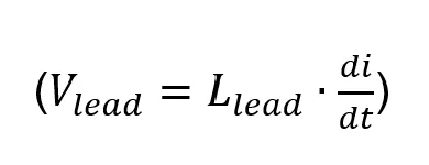
Longer leads result in higher inductance values; however, higher inductance values result in slower change in the current and, thus, in lower di/dt values.
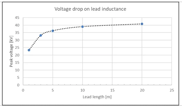
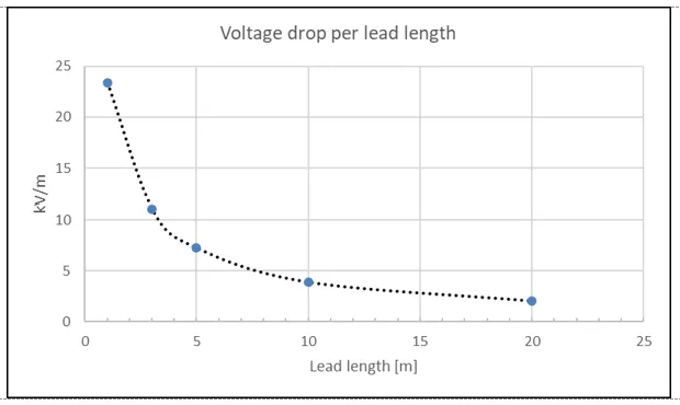
As shown in Fig. 12, a non-linear increase of the inductive voltage drop occurs due to the cumulative effect of these two factors. For longer lead lengths, the voltage drop per meter decreases (see Fig. 13). Moreover, additional simulations indicated that an increase in the bonding lead length from 10 m to 30 m does not impact on the initial peak overvoltage across the sheath interruption as well as its steepness.
Impact of SVL Selection on Charge Transfer
Typically, two main parameters are considered in SVL selection process: a) continuous operating voltage, Uc, and b) protection level, Upl. In most cases, Uc is selected by considering the maximum induced voltages on the sheath during fault conditions. In some cases, the continuous operating voltage is selected to be even higher than the HVDC withstand voltage of the sheath; this allows the after-installation voltage testing of the sheath without the need for disconnecting the SVLs. Upl is selected by considering the insulation withstand levels of the cable sheath and of the cross-bonding joint in combination with the inductive voltage drop on the bonding leads.
Although international guidelines do not make specific reference to charge transfer capability, the latter can have significant impact on the SVL selection process. For example, should EMT studies conclude that higher class SVLs are required to meet the charge transfer criteria, this could significantly impact design of the link box and overall cable system design costs. On the other hand, poor SVL selection could lead to possible failures, leaving the sheath bonding system exposed to higher transient overvoltage stresses.
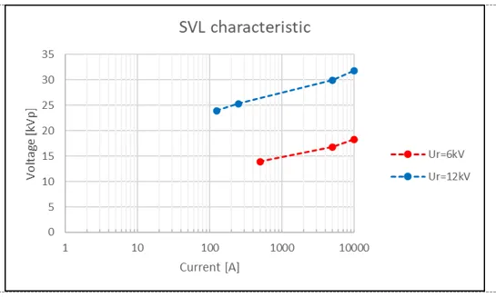
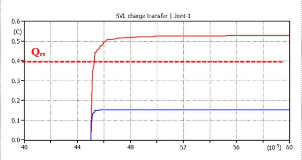
The following example case provides further elaboration on the above; the circuit energization simulation was repeated, by considering the characteristics of an SVL with a lower rated voltage (Ur=9 kV, Uc=7.2 kV, Upl=27.4 kVp). The sheath voltage limiter is still considered an acceptable option with respect to its protection level and the continuous operating voltage. Nevertheless, this SVL offers a lower voltage-current characteristic compared to the SVL of the reference case (Fig. 14). For this particular Siphon circuit, the switching transients resulted in excessive charge transfer levels (Fig.15) and exceedance of the given Qrs datasheet value.
The above research focused on selection of sheath voltage limiters when considering charge transfer capability. The latter is considered essential for insulation coordination of sheath bonding of a cable system to achieve sufficient performance against transient overvoltages. The analysis presented was the result of the root-cause analysis regarding a failed cross-bonding joint of an underground cable system in a 380 kV Siphon circuit in the Dutch EHV grid.
The electromagnetic transient analysis showed that the substation of switching determines peak overvoltages across the sheath interruption in the cross-bonding joint under study. More specifically, the peak overvoltages slightly exceed the specified lightning insulation withstand level of the sheath interruption when energizing the mixed cable-line cable from substation A. Moreover, bonding lead length is an important parameter for peak overvoltage across the sheath interruption. For longer lead lengths, inductive voltage drop per meter decreases, which results in a ‘saturation-like’ voltage drop-lead length characteristic.
Lastly, EMT analysis showed that SVL selection should consider charge transfer capability. Although the continuous operating voltage and protection level may meet SVL requirements, poor selection with respect to charge transfer capability could lead to exceeding data sheet guaranteed values. Possible failure of a sheath voltage limiter could leave the sheath bonding system exposed to excessive transient overvoltage stresses.
References
[1] CIGRE Technical brochure 797, Sheath bonding systems of AC transmission cables – Design, testing and maintenance, 2020
[2] IEC 62067, Power cables with extruded insulation and their accessories for rated voltages above 150 kV (Um=170 kV) up to 500 kV (Um=550 kV) – Test methods and requirements, 2022
[3] IEC 60840, Power cables with extruded insulation and their accessories for rated voltages above 30 kV (Um=36 kV) up to 150 kV (Um =170 kV) – Test methods and requirements, 2020
[4] IEEE P575/D13Approved draft guide for bonding shields and sheaths of single-conductor power cables rated 5 kV through 500 kV, 2014
[5] IEC 60099-5, Surge arresters – Part 5: Selection and application recommendations, 2018
[6] G. Hoogendorp, Steady state and transient behaviour of underground cables in 380 kV transmission grids, TU Delft, 2016
[7] Netcode elektriciteit, 2016
[8] K. Velitsikakis, A. Kumar, M. Faragalla, R. Zuijderduin, Failure Investigation Analysis for Switching Overvoltage Stresses in a Cross-Bonding Joint of a 380kV Siphon Underground Cable System in the Netherlands, CIGRE NRCC Symposium, 2025
[9] EMTP-ATP
[10] IEC 60071-4, Insulation coordination – Part 4: Computational guide to insulation coordination and modelling of electrical networks, 2004
[11] A. Khamlichi, G. Denche, F. Garnacho, G. Donoso, A. Valero, Location of sheath voltage limiters (SVLs) used for accessory protection to assure the insulation coordination of cable outer sheath, sectionalising joints and terminations of high voltage cable systems, CIGRE Session, Paris, 2018