Sheath voltage limiters (SVLs) are arresters that reduce risk of cable damage by limiting transient voltages on cable sheaths. SVLs facilitate single point bonding of cable sheaths, which reduces steady-state circulating current losses. As is the case for phase arresters, SVLs are sized so that conduction current is negligible during normal or emergency operation. But during transients that induce high sheath voltages, SVLs conduct current to limit the voltage.
Steady-state sheath voltages are kept within limits by proper selection of cable section lengths, grounding the sheaths at strategic locations and applying sheath cross bonding for field cancellation. If sheath grounding or application of SVLs are performed improperly, the SVL and the cable itself are at greater risk of damage.
This edited past contribution to INMR by experts at Power Engineers in the United States provided basic information about proper SVL operation and focused on consequences to SVLs in the event of failure to ground the cable sheath.


Sheath Induced Voltages
It is important to first understand the fundamentals of induced voltages on cable sheaths and Fig. 1 shows a simplified cable cross-section. While actual cables include additional layers, these prominent layers are sufficient for the purpose of this discussion. Any voltage on the sheath contributes to voltage difference between core and sheath and between sheath and ground. Typically, the insulation provided by the jacket is the controlling factor for maximum allowable sheath voltage. Typical jacket materials have a breakdown voltage in the range of 20-100 kV/mm. If the jacket is compromised, this can lead to further deterioration and cable failure.
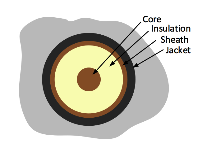
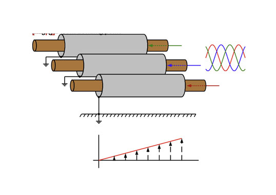
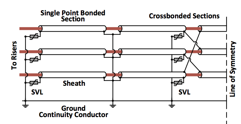
Fig. 2 is a representation of a horizontal cable arrangement but with insulating components not shown. Each core conductor is surrounded by a concentric sheath, which is grounded at one end. From Faraday’s Law and Lenz’s Law, AC current flowing in the core induces a longitudinal voltage in the conductor sheath. Since one end of the sheath is grounded, the induced voltage appears between sheath and ground at the open end.
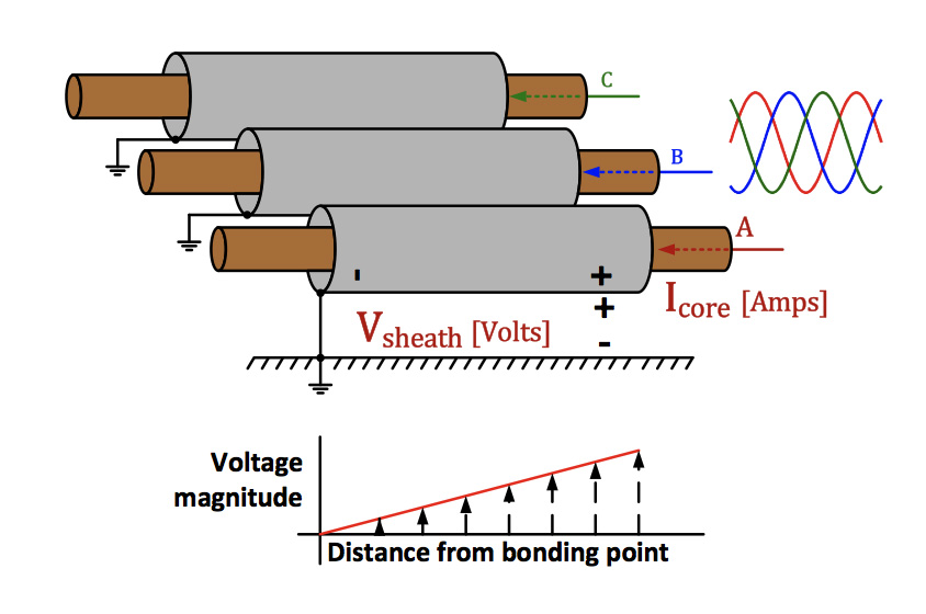
Distance between phases is often relatively small in the case of cable installations. Therefore, currents in adjacent phases and other nearby circuits should be considered when calculating the voltage induced in any sheath. If the phase currents are balanced (i.e. same magnitude with phase angles 120° apart), field cancellation effects can help reduce severity of induced voltage. Single-phase installations that do not benefit from field cancellation could see higher induced sheath voltages for the same core current.
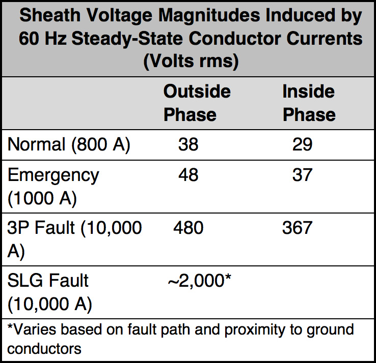
IEEE Standard 575 and references cited at the end of this discussion provide methods for calculating sheath-induced voltages. Simulation can also be used but care must be taken to properly model return currents and electromagnetic coupling between sheaths, phase conductors and ground conductors. Table 1 offers an example showing results calculated using equations from IEEE 575 and verified with simulation using ATP-EMTP. A 230 kV XLPE insulated cable is arranged horizontally with 0.25 m spacing (0.8 ft). Section length is 305 m (1000 ft) and the sheaths are grounded at one end. Jacket thickness is 3.8 mm (0.15 in) and load and reported fault currents have a frequency of 60 Hz. Note that none of the induced voltages approach breakdown strength of the jacket (i.e. approx. 76 kV = 3.8 mm x 20 kV/mm).
Transients such as those from switching or lightning have higher frequency content and couple more effectively through cable capacitance. This can cause much higher voltage difference between sheath and external ground. Indirect lightning strikes to ground can also increase ground potential, causing a large transient voltage to appear across the jacket.
A simple ATP-EMTP simulation illustrates the impact of switching transients. A surge type source with 10 µsec rise time, 350 µsec tail time and amplitude of 2.0 per unit on 230 kV was applied to the core of one phase of the 230 kV XLPE cable described above. Transient voltage on the sheath of the same phase reached a peak value just above 110 kV while sheaths on adjacent phases saw peak transient voltages of about 80 kV. Depending on material and thickness of the jacket, these voltages could be high enough to result in puncture.

Basics of SVLs
More detail is available in Refs #6, 7, 8 & 9. A typical insulation coordination approach using SVLs to protect a cable jacket consists of the following:
1. Maximum continuous operating voltage (MCOV) of the SVL must be selected so that it will not conduct current for any sheath voltages induced by the maximum normal or emergency steady state load currents or fault currents flowing in core conductors;
2. The SVL is selected with a volt-current (V-I) characteristic that results in conduction for high voltages induced from transient events, such as switching and lightning. Since insulating properties of the jacket are not well defined and not assured by industry standards, ample protective margins are recommended;
3. The SVL must have an energy absorption capability sufficient for possible events that could result in SVL conduction. Total energy ratings and temporary overvoltage curves provided by manufacturers should be consulted.
SVLs are applied at locations corresponding to sheath-to-ground voltage peaks. This includes the open end of single point bonded cable sections or at section terminations where the sheaths of cross-bonded cable configurations are transposed (see Fig. 3).
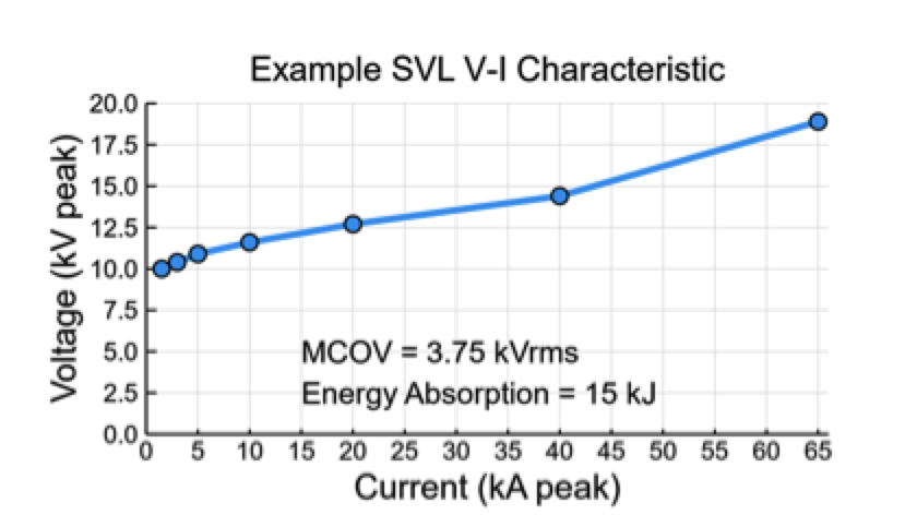
Rigorous coverage of insulation coordination analysis for SVLs is beyond the scope of this paper and additional information about specification of SVLs is found in the literature. Fig. 4 shows the characteristics of an SVL selected for the 230 kV XLPE cable installation example. Applying this SVL and simulating the switching transient described above results in clamping of sheath voltages to about 11 kV (down from 110 kV). Transient SVL current peaks at about 5500 Amps and SVL energy absorption is approx. 615 Joules.
Impact of Ungrounded Sheath
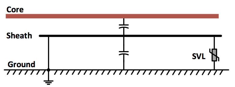
Fig. 5 offers a circuit representation of one phase of a single point bonded system. One end of the sheath is connected directly to ground and an SVL is connected between sheath and ground at the other end. The capacitor circuit elements represent the sum of the distributed capacitance between core and sheath and sheath and ground. So long as one end of the sheath is grounded, sheath-to-ground capacitance has negligible effect. Steady-state induced sheath voltages in this case are due primarily to magnetic fields from core currents which couple to the sheath (i.e. mutual inductance, not shown).
If connection to ground is broken or not installed, electrostatic effects dominate and voltage at the sheath will be determined by a voltage divider using the respective capacitances. If resulting sheath voltage is higher than the SVL’s V-I curve, the SVL will conduct. Returning to the 230 kV cable discussed above, assume cables are direct-buried in conductive ground (i.e. ground potential reference at the surface of the cable jacket). Capacitance per unit length between concentric cylindrical conductors can be calculated using equation (1). Table 2 lists input data and results of the voltage divider calculation, overlooking presence of the SVL.
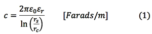
where:
ε0 is the permittivity of free space;
εr is the relative permittivity of the dielectric;
rs is the inner radius of the outer conductor; and
rc is the inner radius of the inner conductor.
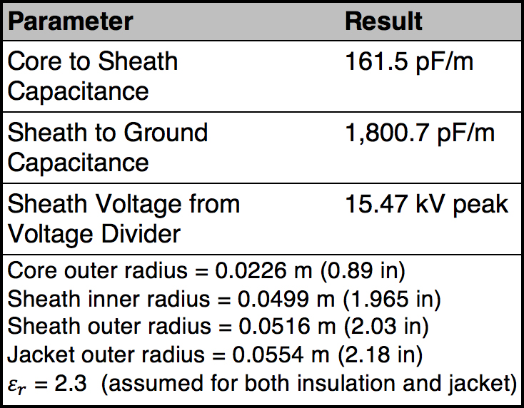

Comparing sheath voltage result to the V-I curve in Fig. 4, it can be seen that voltage is high enough to cause the SVL to conduct. However, the steady-state current cannot be found directly from the SVL’s V-I characteristic because it is limited by core-to-sheath capacitance. Manufacturer data typically does not include V-I characteristics for currents below 500 Amps. If nominal voltage of the cable system is much larger than the lowest published voltage of the V-I characteristic curve, current through the SVL can be approximated by assuming all the voltage drop is across the core-to-sheath capacitance. The larger the voltage across the SVL with respect to nominal system voltage, the more this approach will tend to overestimate SVL current. In this case, current will be limited to:
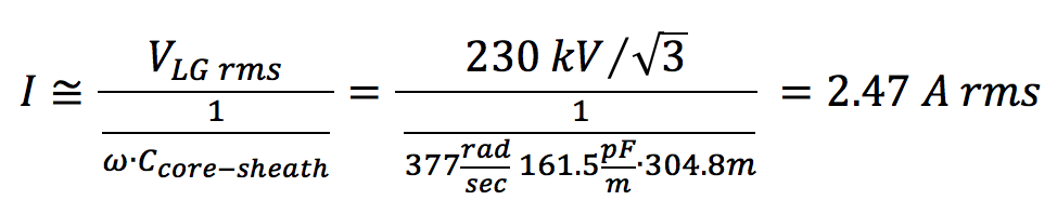
Even though this current is low, the heating effects are substantial and can result in rapid deterioration and failure of the SVL. (This will be explored below). An error that is occasionally made in conjunction with failure to ground the sheath is to install SVLs at both ends of the sheath. The result is similar but the current in each SVL will be approximately half the total capacitive current. The example above is for a direct-bury cable in which the reference ground surrounds the jacket. This configuration was selected for simplicity in calculating sheath-to-ground capacitance. But what about other cable configurations? Figs. 6 and 7 compare results of electrostatic finite element analysis for three cable configurations. .
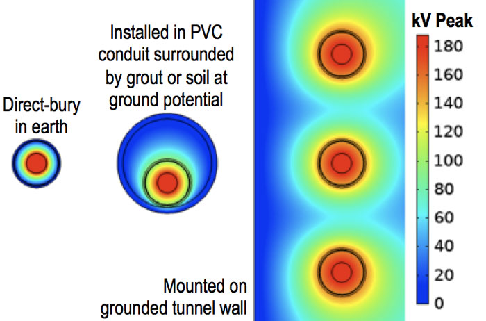
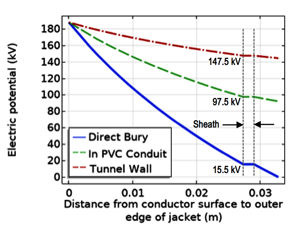
In each case, distance between sheath and ground plane is successively larger and such larger distances result in reduction in capacitance between sheath and ground. The corresponding increase in capacitive reactance between sheath and ground causes an increase in sheath potential due to the voltage divider. Note that these are steady-state voltages the sheath would see without an SVL connecting it to ground. In all three cases, the example SVL would conduct. The further the sheath is from reference ground, the higher will be the floating potential. However, current in the SVL will be approximately the same in all three cases since it is the core-to-sheath capacitive reactance that limits the flow.

Thermal Impact of Induced Current
Estimated SVL current in an ungrounded sheath, as discussed above, was 2.47 Amps rms (about 3.5 Amps peak). In reality, this current will be a distorted waveform since the SVL only conducts for a portion of each cycle. Fig. 8 shows a simulated result of SVL currents for each phase of the 230 kV case installation having ungrounded sheaths. The simulation uses the SVL’s V-I characteristic from Fig. 4. The program estimates the V-I characteristic for operating points outside those specified by manufacturer data. Variations and asymmetry in current waveforms are due to the non-linear V-I characteristic and series capacitance as well as from variation in induced sheath voltages caused by asymmetry inherent in the horizontal cable arrangement (A to B spacing = B to C spacing ≠ A to C spacing).
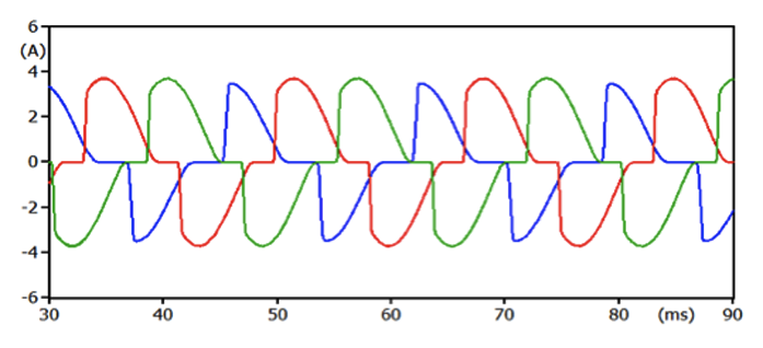
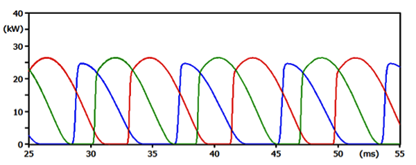
Fig. 9 plots power absorbed by the SVLs. Peak power is about 26.5 kW and average power is about 13.3 kW. This level of power dissipation would cause rapid heating and failure of the SVL given that a typical SVL has a maximum operating temperature of 60°C (140°F). If temperature is too high, properties of the zinc oxide blocks change and a thermal runaway condition can occur.
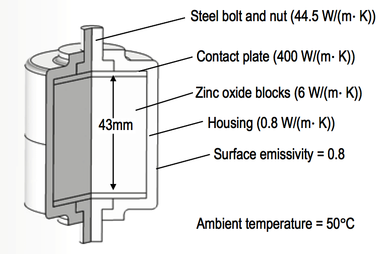
To estimate current required to reach maximum operating temperature, a thermal finite element analysis was prepared for a representative SVL (see Fig. 10 which lists the thermal characteristics of the model). The zinc oxide block was set as a variable volumetric heat source with heat loss through conduction and radiation at the housing-to-air interface. The SVL model was placed in a region about the size of a link box enclosure. Boundaries of the link box region were set to a constant temperature of 10°C (50°F).

The simulation iterates until equilibrium is reached between heat sourced by the ZnO blocks and heat flow out of the SVL. Maximum temperature in the SVL was then recorded. This was performed for a range of ZnO heat generation levels. Post processing calculations determined conduction currents that would produce the ZnO heat energy assuming a 5 kV residual voltage across the SVL and assuming the instantaneous power is about twice the average power. Fig. 11 provides results of the analysis. These values are only an approximation but nonetheless demonstrate that even little steady-state current is sufficient to push an SVL to its thermal rating.
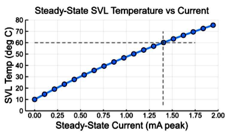
SVL currents in the milliamp range are possible for distribution level circuits with short section lengths. Under these circumstances, the SVLs could operate for some time before failing and would be sensitive to ambient temperatures and other thermal conditions.

Conclusions
Sheath voltage limiters are important in order to reduce cable losses and to protect cable jackets from lightning and switching transients but their use requires that the sheath be properly grounded. Failure to ground the sheath results in a floating potential condition. If the steady-state sheath voltage exceeds the V-I characteristics of the SVL, the unit will begin to conduct continuous current, limited by cable core-to-sheath capacitance. If an ungrounded condition exists on a transmission cable sheath, SVL currents can be in the range of a few Amps. This corresponds to an instantaneous power in the range of tens of kW and SVL failure will then likely occur quickly. The process leading to failure can take longer on short distribution circuits where capacitive currents might be in the milliamp range. Analysis of ungrounded conditions is not necessary for proper specification of SVLs. However, the conceptual analysis and calculations completed above are for training purposes and also provide information to help troubleshoot SVL failures.
References
[1] Lapp Tannehill, “Insulation/Jacket Materials: Physical Properties Chart,” [Online]. Available: https://www.lapptannehill.com/resources/technical-information/insulation-jacket-materials-physical-properties-chart. [Accessed 16 September 2019].
[2] IEEE Power and Energy Society, “IEEE Std 575-2014, IEEE Guide for Bonding Shields and Sheaths of Single-Conductor Power Cables Rated 5 kV through 500 kV,” IEEE, New York, NY, 2014.
[3] C. Adamson, E. Taha and L. Wedepohl, “Determination of the Open-Circuit Shath Voltages of Cable Systems,” IEEE Proceedings, vol. 115, no. 8, 1968.
[4] M. Shaban, M. A. Salam, M. A. B. Sidik, Z. Buntant and W. Voon, “Assessing Induced Sheath Voltage in Multi-Circuit Cables: Revising the Methodology,” in IEEE Conference on Energy Conversion (CENCON), Johor Bahru, Malaysia, 2015.
[5] V. K. Gouramanis, G. C. Kaloudas, T. A. Papadopoulos, K. G. Papagiannis and K. Stasinos, “Sheath Voltage Calculations in Long Medium Voltage Cables,” in IEEE PowerTech, Trondheim, 2011.
[6] J. Woodworth, “Sheath Voltage Limiters Protect HV Power Cables,” Zimmar Holdings Ltd./INMR, 9 February 2019. [Online]. Available: https://www.inmr.com/sheath-voltage-limiters-protect-power-cables/. [Accessed 18 September 2019].
[7] D. Cao, X. Liu and X. Deng, “The Suitability Analyses of Sheath Voltage Limiters for HV Power Cable Transmission Lines,” in 2nd International Conference on Electrical Materials and Power Equipment, Guangzhou, China, 2019.
[8] A. Heiss, G. Balzer, O. Schmitt and B. Richter, “Surge Arresters for Cable Sheath Preventing Power Loss in MV Networks,” in 16th International Conference and Exhibition on Electricity Distribution, IET, Amsterdam, Netherlands, 2001.
[9] Insulect, “Sheath Voltage Limiters,” 2019. [Online]. Available: https://insulect.com/products/sheath-voltage-limiters-svl. [Accessed 17 September 2019].
[10] C. R. Paul, Analysis of Multiconductor Transmission Lines, Second Edition, Hoboken, NJ: John Wiley & Sons, 2008.
[11] J. He, R. Zeng, S. Chen and Y. Tu, “Thermal Characteristics of High Voltage Whole-Solid-Insulated Polymeric ZnO Surge Arrester,” IEEE Transactions on Power Delivery, vol. 18, no. 4, 2003.
[12] S. B. Lee, S. J. Lee and B. H. Lee, “Analysis of Thermal and Electrical Properties of ZnO Arrester Block,” Current Applied Physics, vol. 10, no. 1, pp. 176-180, 2010.