Over the past decades, use of extruded XLPE cables in underground transmission systems has increased steadily to the point that they now account for the vast majority of all new installations. This near total shift away from oil and paper insulation has made it worthwhile to look for improved methodologies for testing solid dielectric cables.
At present, there are two primary IEC standards and one ICEA standard that prescribe the methods and requirements for type testing as well as commissioning testing of transmission class cables.
This past article contributed to INMR by testing staff from Kinectrics in Toronto reviewed procedures that form the basis for these standards with a view to performing type test qualification to IEC and ICEA concurrently. It also proposed techniques to make these tests more efficient and economical.

Standards for Laboratory Type Tests
Type tests for solid insulation HV cables are described in two IEC standards and one ICEA standard:
• IEC 60840 Edition 4.0 2011-11 “Power cables with extruded insulation and their accessories for rated voltages above 30 kV (Um = 36 kV) up to 150 kV (Um = 170 kV) – Test methods and requirements”
• IEC 62067 Edition 2.0 2011-11 “Power cables with extruded insulation and their accessories for rated voltages above 150 kV (Um = 170 kV) up to 500 kV (Um = 550 kV) – Test methods and requirements”
• ICEA S-108-720-2012 “Standard for Extruded Insulation Power Cables above 46 through 345 kV”.
CLICK TO ENLARGE
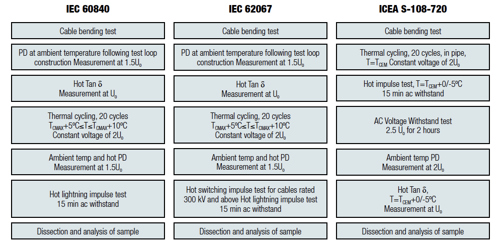
The electrical type test requirements for these standards are similar but not the same (see flowcharts in Fig. 1). As evident, the procedures mandated are different only in that cables rated for system voltages of 300 kV and higher require a hot switching impulse test while those rated below do not. The procedures outlined in the ICEA standard differ more significantly, as follows:
1. Different sequence of tests;
2. Higher required elevated test temperatures;
3. Requirement that cable loop is installed in a pipe;
4. No requirement that cable systems rated 300 kV and above be subjected to hot switching impulse test;
5. Requirement that hot impulse test be completed by breakdown (or that cable system is tested to limit of test equipment);
6. PD test performed at higher test voltages;
7. Requirement for 2 hour AC withstand test at 2.5Uo.

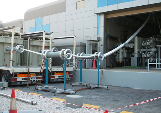
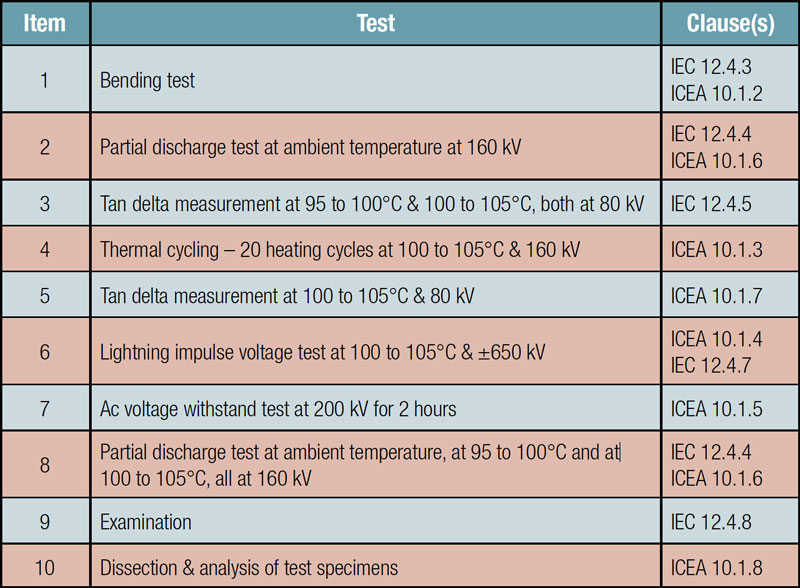
Typically, cable manufacturers and users prefer a single test program to satisfy the requirements of both standards and this can be done by utilizing the procedure outlined in Table 1 and applicable to cables systems rated for systems up to 150 kV. Since this procedure combines the most severe factors from each specification, passing this program results in qualification to both standards.
Cable System in Accordance with IEC & ICEA Standards.
CLICK TO ENLARGE
Developments in Laboratory Type Testing
In order to improve the accuracy and integrity of cable type test procedures, several innovations have now been developed. These include a method of continuous heating throughout the impulse testing as well as eliminating the need for the dummy loop traditionally used during thermal cycling tests.
Impulse Test Heating
During the impulse testing segment of type testing, conductor temperature must be maintained within given limits linked to the maximum operating temperature of the cable system. Application of the specified 10 positive and 10 negative impulses takes time since impulses are typically applied every 2 minutes. This means that about 30 minutes are required for each set of required positive and negative impulses when taking into account the need for conditioning impulses at reduced levels.
Concerns about damaging the heating system during possible impulse breakdown have lead some test laboratories to heat the cable to the required temperature before application of the impulse sequence test. Then, upon initiation of the impulse applications, the heating source is disconnected.
If the cable is not heated during the 30 min period required for each set of positive and negative impulse applications, its temperature can drop significantly below the required limits. To address this issue, a method of heating the cable between successive impulse applications has been developed which ensures that the temperature limits required by the standards are maintained throughout impulse testing.

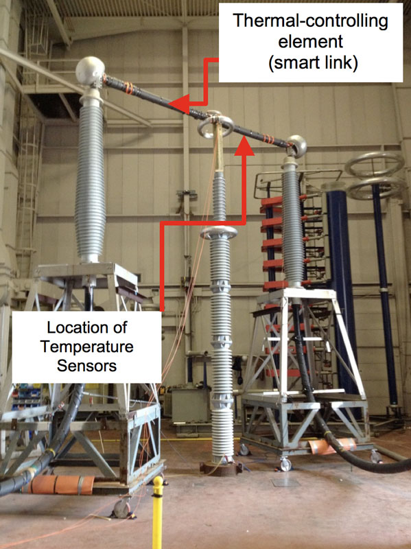
Eliminating the Dummy Loop
The protocol used during thermal cycling testing requires that the cable system undergo a heat cycling voltage test over the relatively long period of 20 days. The test involves heating, soaking and cooling the cable system for 20 cycles while the system is energized according to the specific voltage class of the cable and accessories. Each cycle lasts 24 hours while heating is maintained for 8 hours. During the first 6 hours, the cable conductor must reach a specified temperature and this must be maintained within a 5°C limit over the next 2 hours. The cable is then allowed to cool naturally for 16 hours.
When performing this test, the standards suggest a control loop utilizing an identical cable. This ‘dummy’ loop is heated in the same manner as the test loop and the temperature of its sheath and conductor are continuously recorded. The only difference between the loops is that the dummy loop is not energized and therefore thermocouples can be directly attached to the conductor in order to measure its temperature.
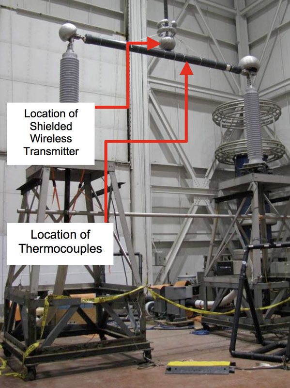
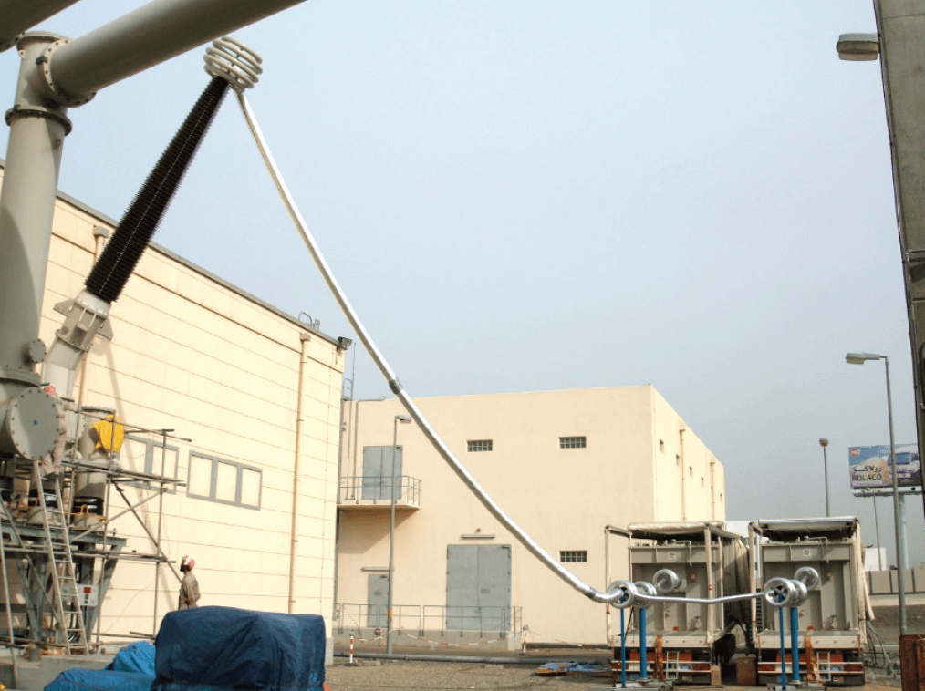
The need for such a dummy loop has effectively been eliminated by implementing a mechanism for transmitting data under voltage using a wireless data logging transmitting system. Basically, conductor temperature is measured by means of a smart link telemetry system installed on a length of the same cable being tested. Thermocouples are attached directly to the surface of the conductor as well as to the sheath of the control cable and connected to a wireless transmitter nearby. The control cable is then installed between the outdoor terminations in series with the test loop such that the conductor in this length of cable carries the same current as the test loop itself. Use of such a ‘smart link’ allows for electrically isolated temperature measuring points directly on the conductor and on its sheath.
CLICK TO ENLARGE
New fibre-optic based technologies for monitoring temperature under voltage are now available. The advantage of such a system lies in the fact that the fiber-optic cables are isolated and can be attached directly to the energized conductor. Such a set-up allows temperature reading of the smart loop’s conductor to be captured on a continuous basis, thereby enabling automatic control of the test loop heating current. These minor modifications to the temperature sensing elements combined with custom programming allow the system to be tailored to the application.
A fiber-optic temperature monitoring and control system as described above has already been successfully tested in monitoring mode during a 132 kV cable system type test. Moreover, it is now being deployed as the primary monitoring and control system for type testing of 240 kV cable.
CLICK TO ENLARGE
Commissioning Tests for HV XLPE Cable Systems
Traditionally, due to lack of AC high voltage power supplies capable of energizing several kilometers of cable, DC overpotential tests similar to those used for fluid-filled cables have been applied. However, possible problems caused by space charge injection during such testing resulted in DC tests being abandoned for cables insulated with solid extruded polymers. Lack of alternative forms of external energization has led to the so-called ‘soak test’ under which the newly installed cable is put on potential for a 24-hour period. Unfortunately, there have been cases reported of subsequent cable and accessory failures within only a short time after the tested cable system was placed into service.
Availability of variable frequency AC power supplies has since enabled after-laying high voltage testing of XLPE-insulated transmission cables up to 400 kV and over 20 km in length. In this regard, application of AC overpotential testing in conjunction with partial discharge (PD) testing can aid in assuring reliability of a new cable installation.

Test Equipment
High Voltage Power Supply
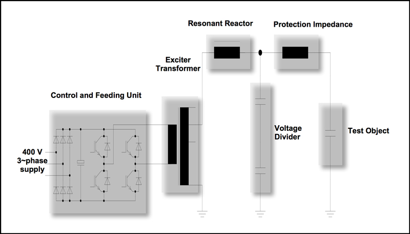
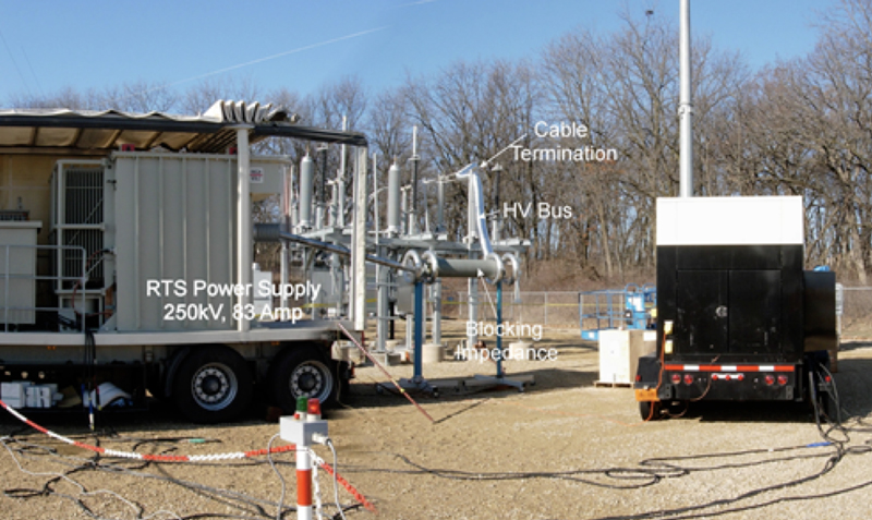
The high voltage power supply employed is a 260 kV, 83A variable frequency resonant test set (RTS) that complies with IEC standards 60840 and 62067 and operates within the frequency range 20-300 Hz. A schematic of the test setup is illustrated in Figure 2. As can be seen, a blocking impedance is placed between the power supply and the high voltage connection to the cable under test with two goals in mind: firstly, the blocking impedance protects the RTS in the unlikely event of cable failure; secondly, it effectively filters any high frequency noise originating from the RTS and improves the signal-to-noise ratio of the power supply when performing PD measurements.
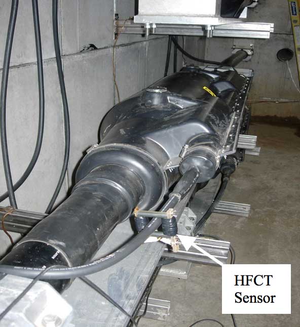
A capacitive voltage divider provides for a voltage reference for the control unit of the power supply. The common point grounding of the entire test circuit is connected to station ground. A 6 inch (15 cm) wide copper foil provides a high frequency ground path while a stranded, insulated aluminium conductor positioned directly on top of the copper sheath constitutes the power frequency ground. Signal coupling is provided by attaching a High Frequency Current Transformer (HFCT) sensor around the ground link from the cable joint toward the link-box. High frequency currents induced as a result of any partial discharge activity in the joint or in the cable section will be coupled to the HFCT sensor and measured by a conventional partial discharge monitor.
CLICK TO ENLARGE
CLICK TO ENLARGE
The commercially available partial discharge monitor used has a 350 kHz to 800 MHz bandwidth and measures the amplitude (in mV) as well as phase angle of any signal detected. A pulse count rate for various categories of magnitudes and phase-angles is also generated. The phase angle reference is provided by a low-frequency winding embedded in the HFCT sensor.
CLICK TO ENLARGE
Test Method
While IEC 60840 and 62067 provide basic guidance on the waveform, frequency and prescribed voltage to be employed during the overvoltage test, there is still no standard prescribed procedure for PD measurements. As such, there is some variation in the measurement procedures employed by various service providers in this field.
The measurement protocol followed in the tests described here consists of the following:
1. Upon tuning the high voltage power supply to the appropriate resonant frequency, a relatively low voltage (on the order of 30 to 40 kV) is applied for two minutes during which various diagnostic parameters are checked to ensure that the system is functioning properly.
2. Voltage is increased to the nominal line-to-ground potential (U0) and held for a further two minutes while diagnostic parameters are confirmed as normal.
3. The voltage is raised to the prescribed level specified in the IEC standards for a period of one hour.
In order to enable performing PD measurements on all accessories during the limited 1-hour hi-pot test, PD detectors can be installed at each of the accessories in the circuit. Signals from these devices are then fed back to a remote test operator for display and analysis. This approach requires the availability of a communication path between the individual joints and the location of the test operator – something that is now increasingly possible as more and more installations of HV cable incorporate fiber communication links into the initial work. This approach, while expensive, has significant advantages in that each sensor point can be observed simultaneously in real-time.
Where such communication networks are not available, the PD must be recorded sequentially at each individual accessory. For significant cable lengths, the time required to carry out these measurements usually exceeds the one-hour hi-pot test duration. In these cases, the PD levels at the maximum possible number of joints are recorded during the one-hour hi-pot test, while the remaining accessories are PD tested at an applied voltage of between Uo and the specified one-hour hi-pot level. This level must be agreed to by the parties involved and has usually been in the range of 1.2 Uo.
Field Experience
Numerous tests have been performed in various locations in the Middle East and across North America involving XLPE-insulated cables from 66 through 380 kV and with circuit lengths ranging from 3 to 30 km. Typically, those circuits rated at 220 kV and higher have required use of two resonant test systems operating in parallel.

CLICK TO ENLARGE
CLICK TO ENLARGE
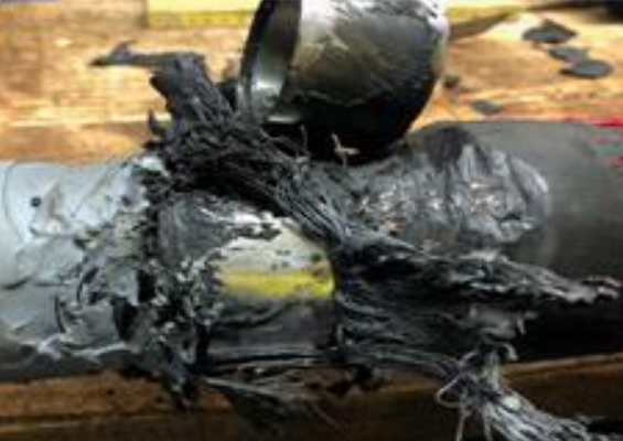
The majority of circuits subjected to such overpotential testing successfully withstood application of the prescribed voltage for one hour. However, in a small number of cases, there were dielectric breakdowns and these failures occurred almost exclusively either in or close to a joint or termination. Typically, defects in the accessories were attributed to problems with installation procedures rather than to deficiencies in design or materials. For example, there was one instance of cable failure where mechanical damage during transport or storage was suspected as root cause.
It may seem attractive to perform PD measurements at the terminals of the cable circuit rather than at individual joints. However, it is well known that problems due to signal attenuation and dispersion limit the lengths of cable where this method could be successfully applied. Detection of PD-related phenomena occurring several kilometres from the detection point requires that the measurement bandwidth be relatively low. Such techniques therefore suffer from problems due to relatively high background electrical interference associated with field measurements. Moreover, although various steps are taken to mitigate the effect of switching noise from the high voltage power supply, these signals will also be present and add to the difficulty of separating PD signals from background noise.
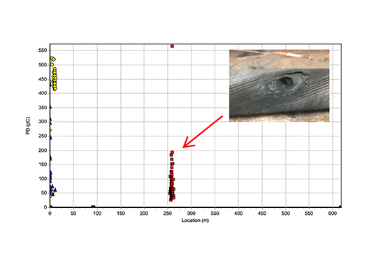
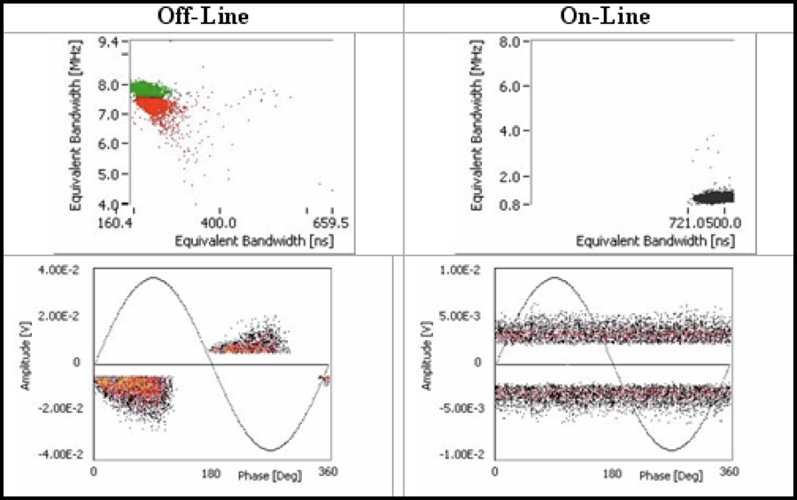
A critical question when making PD measurements relates to establishing pass/fail criteria for their magnitudes. The simplest and most conservative answer is that any detectable level of PD is too high but many practical issues need to be addressed. Among these are the costs and delays needed to replace any accessory or section of cable. One practical example of attempting to define PD-based acceptance criteria for commissioning testing is illustrated in Figure 3
CLICK TO ENLARGE
The left side of Fig. 3 displays data acquired during the off-line test whereas the right side shows data from the on-line test – both conducted at a voltage of U0. PD activity measured during the off-line test has a frequency content ranging from 7 MHz to 8 MHz whereas minimum, mean and maximum PD magnitudes for the off-line data are 5, 7 and 24 mV respectively. In addition, the phase resolved PD plot for the off-line data shows clusters of negative and positive polarity pulses centered near 45° and 225° phase angle with reference to the phase-to-ground voltage. These are classic locations for phase-to-ground dependent partial discharge data.
However, during on-line testing, measured signal activity is quite different, i.e. frequency content of the signals ranges from circa 800 kHz to circa 2 MHz. In addition, the phase resolved PD plot shows the pulses measured to be located throughout the AC cycle. Consequently, the data acquired during the on-line test relates to electrical noise. This figure demonstrates that no PD signals were present during on-line tests since, if present, these would have been detected simultaneously with the noise signals and would have been identifiable in the frequency domain plot of Figure 3. While there are a number of factors that may account for the differences observed above, a decision was made to put the cable in-service in spite of detectable PD during the off-line test. This circuit is currently operating without incident.
One key point emerging from the testing performed to date is that all of the circuits that successfully withstood the high voltage tests and
One key point emerging from the testing performed to date is that all of the circuits that successfully withstood the high voltage tests and on which no PD was detected have operated without incident since commissioning. Circuits which have only been hi-pot tested without the inclusion of PD testing have experienced some failures. Consequently, the combination of overvoltage and PD testing appears to provide the highest level of confidence in the reliability of the cable, accessories and installation method.

Conclusions
Coordinated development of existing standards for high voltage cable systems allows their effective type test qualification to both IEC and ICEA simultaneously. At the same time, innovations in techniques used to perform standard type testing of HV cables can improve accuracy and efficiency, while also lowering costs.
Numerous solid dielectric transmission cable circuits have been subjected to high voltage and PD testing using this methodology as part of the commissioning process following installation. The majority of cable systems tested successfully met the test criteria. However, a small number suffered dielectric breakdown during the overvoltage test with failures generally located in or in close proximity to accessories. Breakdown of the cable itself is extremely rare.
Where post-failure analysis has been performed, the results are consistent with installation issues or damage to the cable during transport or storage. None of the breakdowns have been attributed to design, materials or processing issues. While there is still ongoing debate regarding the technical and cost issues associated with optimizing PD test procedures for on-site transmission cable testing, experience shows that the combination of high voltage and PD testing of transmission cables is necessary to satisfy industry demands for high reliability.