Development of distributed generation systems has expanded from building level connections (< 600V) to privately owned distribution system connections (> 600V). Often, the intent has been to operate in parallel with the utility service when economically viable while also operating separate from the utility to energize portions of the privately owned distribution system as an intentional island, thus forming a local microgrid. Large rotating generation systems (>2 MW) are often employed in microgrid applications to firm up the renewable power supply. These also act as a spinning reserve for intermittent loads within the microgrid that renewable and battery energy storage power supplies may not be able to supply. Most large generators found in the commercial market are wye connected and use either a high or low impedance grounded neutral. Islanding-capable Battery Energy Storage Systems (BESS) may be connected as an ungrounded source as well. System interconnection points vary widely and depend greatly on the existing distribution system, components and utility service design. Large, privately owned distribution systems traditionally include one or more service transformers that establish the distribution voltage. However, during islanding operation, the service transformer is disconnected from the customer power system to prevent unintentional islanding of the utility system. The voltage is therefore solely established by the distributed generation system.
Many existing distribution systems were originally intended to supply loads from solidly or effectively grounded sources and follow typical utility distribution system design guidelines. Therefore, surge arresters within the system are encountered that are designed for temporary overvoltage (TOV) levels traditionally limited to 125% of phase voltage. Many utility systems maintain this design requirement and generation interconnections are designed to limit the TOV to less than 125% of nominal. However, microgrid applications can pose a challenge to system developers in that utility requirements often end at the interface point and do not extend into the customer-owned distribution system. When considering interconnection of a new generation source to privately owned medium voltage distribution system, there are several options to address the new TOV levels.
This edited contribution to INMR by Jesse Hoffman of Stantec Consulting Services in the United States provides a review of common strategies to address TOV levels in microgrid applications.
Listen to Online Lecture on Surge Arrester Considerations in Microgrids by Jesse Hoffman
System Performance
In solidly or effectively grounded systems, during normal operation the service entrance transformer establishes the ground reference for the overall distribution system. In these systems, the transformer neutral is grounded through a very low impedance connection to ground. This ensures that during line to ground faults, the un-faulted phase voltages do not elevate beyond 125% of the nominal voltage allowing for 80% rated arresters to be used. This holds true when connecting an impedance-grounded or ungrounded parallel generation source to the system since the service entrance transformer remains the primary source of fault current. The voltage drop across its neutral point is very low, thus limiting the un-faulted phase voltage to normal levels (7.35 kV as shown in Fig. 1).
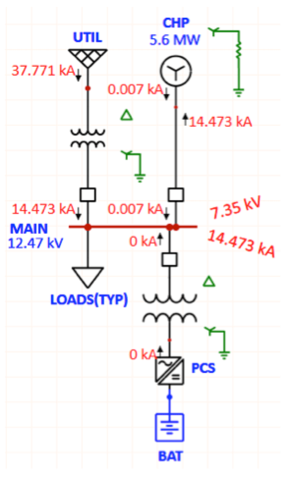
CLICK TO ENLARGE
However, during island operation of the microgrid, the impedance-grounded, or ungrounded generation sources establishes the ground reference given that the service entrance transformer is disconnected from the circuit. During this condition, the ground fault current for a line to ground fault will be low (or near zero for an ungrounded circuit) and the voltage of the un-faulted phases will approach line voltage levels, i.e. 173% of the nominal phase voltage (12.42 kV as shown in Fig. 2). Voltage rise occurs rapidly allowing for quick detection. Actual tripping times tend to be long however, allowing for proper protective coordination and can exceed the surge arrester TOV energy rating. This causes the arrester to conduct current and clamp the voltage to the design level. Over time, this can degrade or damage arresters.
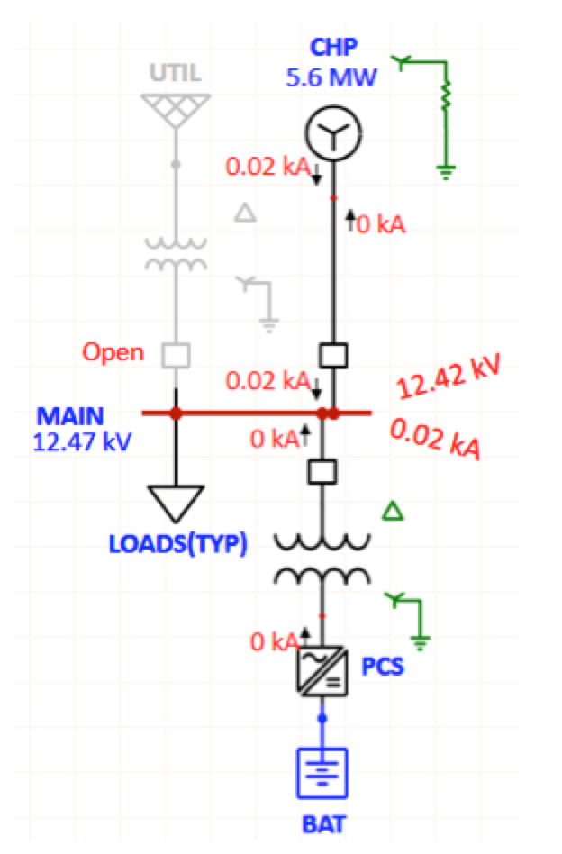
CLICK TO ENLARGE
Considering that there are many arresters in a distribution system, the level of disruption due to this fault and time to repair components can prove significant.
Design Configurations
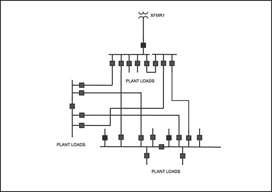
Consider the microgrid configuration in Fig. 2. A large, medium voltage distribution system is privately owned and serves several facilities with only 3-phase loads connected to the system. The new generation source connects to the main incoming switchgear that is fed from a solidly grounded transformer. Prior to the distributed generation project, the system was load serving and did not have islanding capability. The substation includes 8.4 kV MCOV station class arresters that are appropriate for the original installation.

As with most large rotating generators, the generator winding is not 2/3 pitch and therefore, to reduce the flow of 3rd order harmonic currents between generator and main transformer, the generator is high resistance grounded. As indicated in Fig. 2, phase voltages in island mode exceed the MCOV of the arresters during a ground fault event. Evaluation of the arrester overvoltage capabilities is required. If the leakage currents are greater than 1A during the overvoltage, a transient analysis of the arresters is justified. Since TOV limits of the arresters also depend on arrester class, it is important to properly categorize and model each arrester type found in the system. In the subject system, arrester current exceeds 1A [see Fig. 8] and corrective action must be taken. There are several methods to address this problem, including replacement of arresters. Following are the solutions most commonly observed in microgrid installations:
1. Installing Isolation Transformer
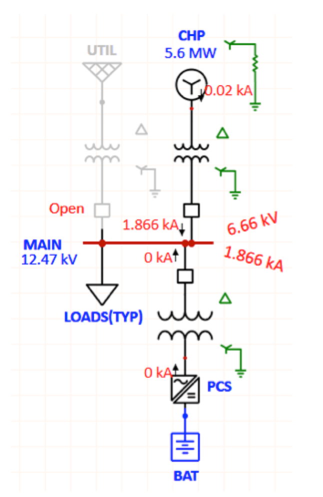
Installation of an isolation transformer can allow the new system to attain similar if not identical performance to a solidly grounded system, provided the winding configuration is properly selected. In most large generation installations, the high voltage winding is configured as wye grounded with a delta generator connected winding. This configuration allows for the generator to remain high impedance grounded, blocks 3rd order harmonic currents from flowing to the utility transformer in normal mode, and provides a ground reference, thus allowing the arresters to remain unchanged. During ground faults, the voltage on the un-faulted phases is much less than the MCOV rating of the arresters [see Fig. 3].

Alternatively, if the energy storage system power conversion system (PCS) is compatible with an ungrounded interconnection, the Delta-Wye transformer can be used for the energy storage system step up transformer. This allows the energy storage system step-up transformer to act as a grounding transformer during island operation, while the generator neutral impedance can remain high [see Fig. 4].
CLICK TO ENLARGE
It must be noted that transformer-winding configuration is of critical importance. Consider the use of a Wye-Wye transformer in Fig. 5. While this type of winding configuration is traditionally lower cost, a review of the Zero Sequence network reveals that this type of winding will not isolate the generator neutral impedance from the distribution system. In this configuration, the transformer no longer provides a ground reference to the distribution system and the TOV levels during ground faults are equivalent to the system shown in Fig. 2.
CLICK TO ENLARGE
CLICK TO ENLARGE
However, application of Wye-Wye transformers between generators and the utility are commonly observed and can be acceptable provided the generator is also effectively grounded and 2/3 pitch, which is typically the case for smaller capacity generators.

2. Adding Grounding Transformer
Addition a grounding transformer at the main switchgear is a suitable alternative to reduce the TOV. The grounding transformer provides a ground reference in the islanded microgrid and, if selected to do so, can achieve voltage results mirroring that of the normal service entrance transformer (7.19 kV as shown in Fig. 6).
CLICK TO ENLARGE
When adding a grounding transformer, care must be taken to ensure that the unit is either switched out of service during normal utility parallel mode or, if the grounding transformer is operated in parallel with the service entrance transformer, that the system is designed for these conditions. Grounding transformers must also be integrated into the protective relay strategy.

3. Using Hybrid Neutral Ground Device
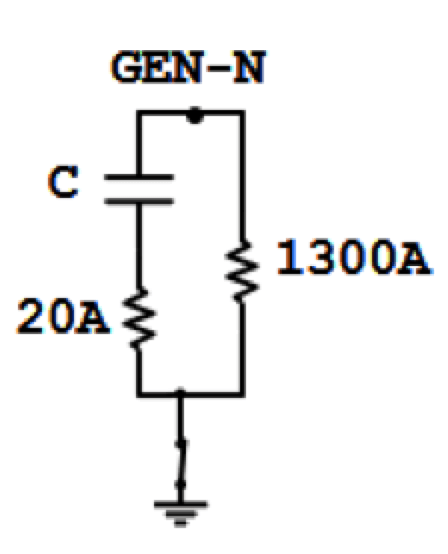
As noted in the cases above, the goal of the system grounding design is to limit the TOV to acceptable levels during island operation while also ensuring flow of 3rd order harmonics is reduced during normal grid parallel mode. This requires that the generation source include low neutral impedance during island mode (to reduce TOV) and high neutral impedance during normal mode (to reduce 3rd order harmonic currents). This gives rise to use of a hybrid neutral grounding device. In such a device, ground impedance is switched from high impedance to low impedance based on the system’s mode of operation. Fig. 7 indicates device ratings for the sample system.
CLICK TO ENLARGE
The resulting TOV during island mode is held to that of normal mode. The added complexity of the grounding device is low and is easily controllable by the system controller.
Listen to Other Online Lectures on Arresters
4. 3V0 Tripping
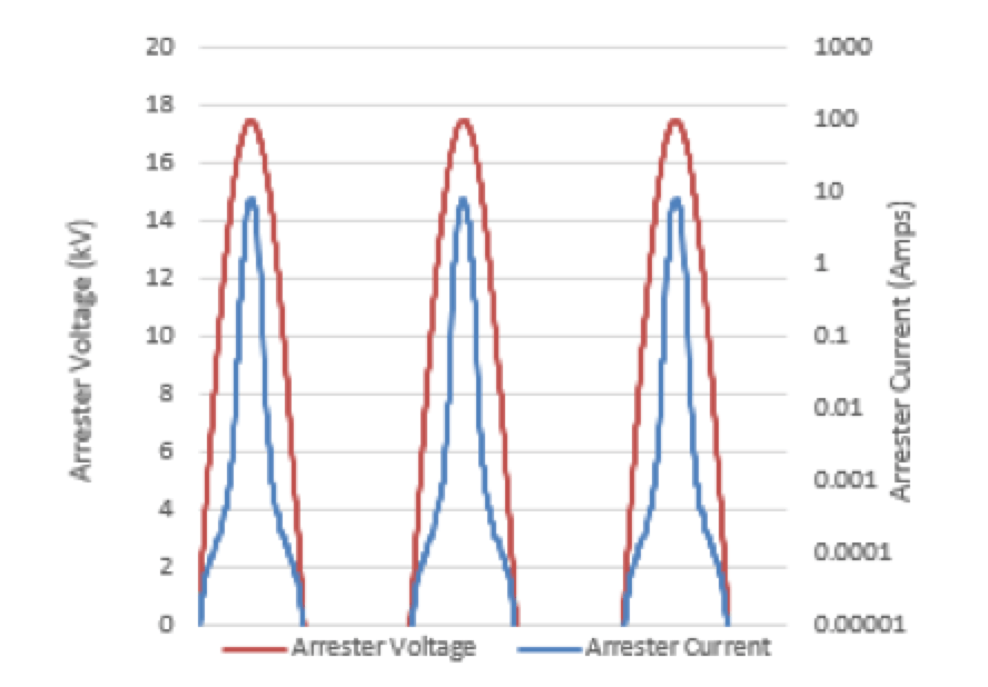
Zero Sequence overvoltage protective relay tripping provides sensitive ground fault detection and can be used to trip generation sources during ground faults in ungrounded systems. This method of protection can be accomplished using either electro-mechanical relays or to be implemented using calculated Zero Sequence voltages in microprocessor relays. Both the voltage trip setting and time delay affect the energy absorbed by arresters during the ground fault. This method of protection will not limit magnitude of TOV but rather only reduce duration and thus energy through the arresters. In the sample system, time delay of the 3V0 protection could be 5 to 10 seconds to allow downstream device tripping to occur. In this case, peak voltage (assuming no other measures are implemented to effectively ground the system) is 17.6 kV. Fig. 8 shows resulting arrester current. The arrester has 9.8 seconds before reaching maximum rated energy.
CLICK TO ENLARGE
5. Replacing Arresters
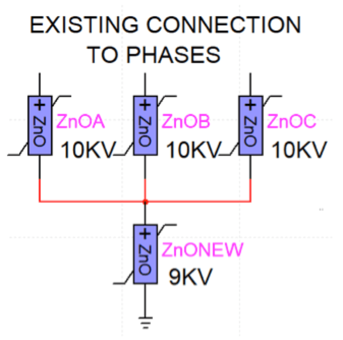
In some cases, replacement of system arresters is unavoidable due to project constraints or technical feasibility. The new arresters should be chosen to ensure that lightning clamping level and system surge protective level are within the acceptable range, while also being rated above the TOV anticipated for island operation. Replacing each arrester per phase of the system is the traditional approach. But if metal oxide arresters are used and the voltage-current characteristics are exactly matched between arresters, the existing configuration can be modified such that the original solidly grounded system rated arresters remain. Arresters can be arranged in parallel, adding a new lower rated arrester at the star point of the existing arresters [see Fig. 9]. The combined arresters perform like a fully rated arrester for line-to-ground faults while for phase-to-phase over voltages, the effective rating of the arresters is much reduced compared to installing new higher rating arresters on each phase.
CLICK TO ENLARGE
Conclusions
As with most design challenges, many different solutions are available to address TOV conditions. Careful evaluation of the system, its ground methodology and the loads served from the system should be conducted during initial microgrid concept development. Oftentimes, generator grounding, winding pitch and system arrester ratings are evaluated during the submission review phase of a project. This can lead to last-minute system wide arrester changes and/or equipment additions during construction. Understanding the interplay between insulation coordination, system grounding, generator pitch and protective device co-ordination is essential for successful microgrid deployment.
References
[1] J. Woodworth, “Understanding Temporary Overvoltage Behavior of Arresters,” 2017.
[2] J. Blackburn and T. Domin, Protective Relaying Principles and Applications, Taylor & Francis Group, 2007.
[3] D. Reimert, Protective Relaying for Power Generation, Taylor & Francis Group, 2006.
[4] A. Hileman, Insulation Coordination for Power Systems, Taylor & Francis Group, 1999.
[5] J. Das, Transients in Electrical Systems, McGraw Hill, 2010.
[6] P. Cardinal, “Generator Pitch and Associated Concerns When Paralleling Generators,” IEEE, 2009.