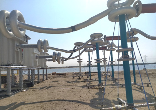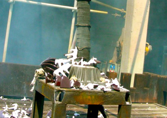
Most reported failures of polymer suspension insulators on transmission lines have been due either to brittle fracture, i.e. mechanical failure, or to flashunder, i.e. electrical failure. These failure modes occur if moisture is allowed to ingress past the rubber weathershed or end fitting seal and come into contact with the internal fiber reinforced plastic core. Such damage, typically the result of improper handling or attack by wildlife, manifests itself through elevated leakage current, corona or flashover. While chemical exposure can also degrade weathersheds, this is usually not as critical.
EPRI in the U.S. first began full-scale, multi-stress accelerated ageing of polymer insulators in 1993 with the goal of better understanding different modes of degradation of rubber weathersheds. Results were found to correlate well with types of degradation and failures observed in service and among the key findings was that corona from end fittings and discharges from water drop corona are primary stressors that can cause degradation. While best practice in insulator design recommends keeping E-field magnitude below corona discharge extinction levels, corona discharges can still occur due to uncontrolled factors. In such cases, the rubber weathershed must be able to endure their presence.
Unfortunately, full-scale testing of insulators is costly and time-consuming, making it difficult to rely on during the product selection and procurement process. As such, there has been a need to develop additional tests that can be included in polymer insulator specifications and that allow utilities to select only those that provide optimum life expectancy and performance. These tests need to be representative of the stresses insulators actually experience during service but must also be repeatable and cost effective.
This edited past contribution to INMR by Andrew Phillips and Timothy Shaw of EPRI in the United States provided background on a small-scale, corona ageing test on the insulator sheath that can be used as part of utility specifications.
Developing Small-Scale Ageing Test
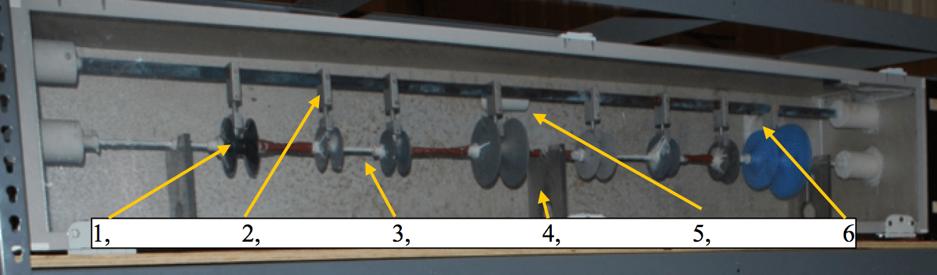
The goal behind development of a small-scale ageing chamber to evaluate performance of polymer insulator samples exposed to corona discharge was to provide utilities with a test they can reference when specifying insulators. Such a chamber tests samples cut from complete insulators and exposes them to corona discharge, similar to what can occur during service. Compared to full-scale ageing chambers, the small-scale chamber aims for lower cost as well as less space and time requirements. The set-up consists of an enclosed aluminum chamber separated into two compartments by an aluminum wall (see Figs. 1 and 2). The larger test compartment enclosed by a polycarbonate door, contains:
1. Test samples;
2. Corona electrodes;
3. Energized buses;
4. Polycarbonate electrode supports;
5. Humidity port;
6. Exhaust ports.
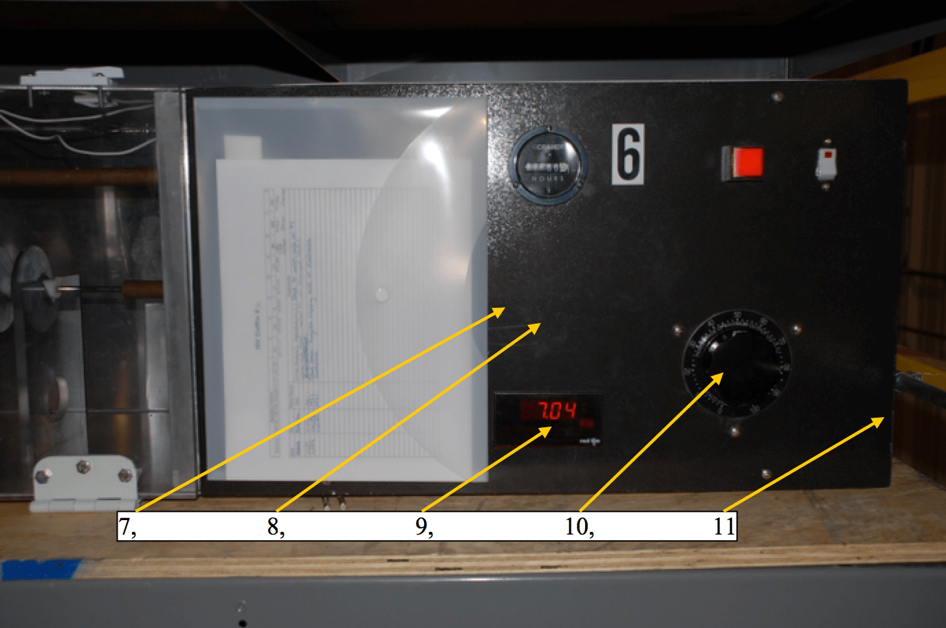
The smaller controls compartment, enclosed by an aluminum panel, contains:
7. Low cost transformer capable of producing ± 7 kV;
8. High voltage probes;
9. Digital voltmeter;
10. Variac;
11. Fuse

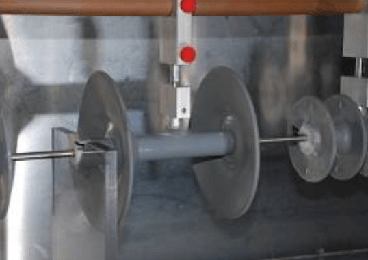
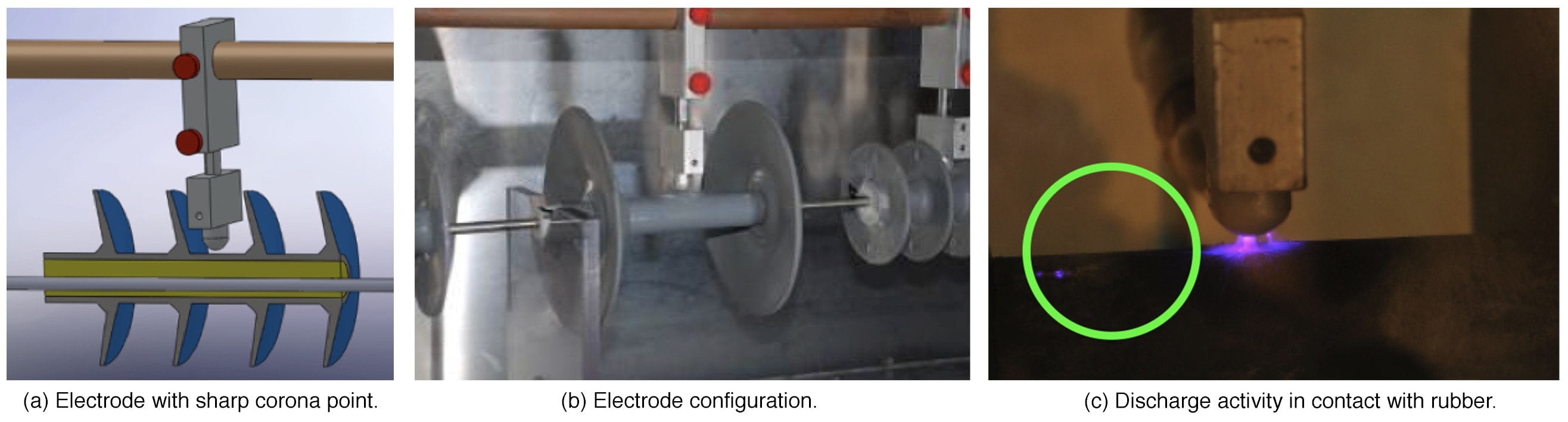
An electrode designed to create a 60 Hz corona source is positioned in proximity to the rubber housing of the insulator section, as shown in Fig. 3. The electrode, manufactured from aluminum, contains a 1 mm tungsten rod from which corona is initiated and is supported by a rod that is energized. A second electrode is installed through the fiberglass rod of the insulator sample to be tested. The location of the hole in the fiberglass rod is selected so that the distance from the surface of the sheath to the upper electrode is 2 mm (0.079 in.). Moreover, distance between the upper electrode and the center of the internal electrode rod is identical for all samples. Since manufacturers offer different sheath thicknesses, the location of the cylindrical hole to the centerline of the fiberglass rod may vary, as shown in Fig. 3a. The lengths of the insulator section also vary depending on manufacturer but, at a minimum, must include at least two sheds with leakage distance of 25 cm from end-to-end. The sheath section considered under test is that between the two sheds.
The test chambers are designed for two types of environments:
Dry Environment
The dry environment chamber operates in the ambient atmosphere and temperature of the laboratory.

Humid Environment
The humid environment chamber has ultrasonic vaporizers plumbed to an inlet port near the middle of the test compartment and subjects samples to high humidity. Recommended humidity is 80%, a level where small discrete droplets form on the surface of insulator samples without impacting the electrode gap.
Testing & Results
Testing and development over the years involved several stages, starting with a dry environment chamber:
• 2011: Dry Environment
• 2011: 100% Humidity Environment
• 2012: Dry Environment
• 2013: 80% Humidity Environment
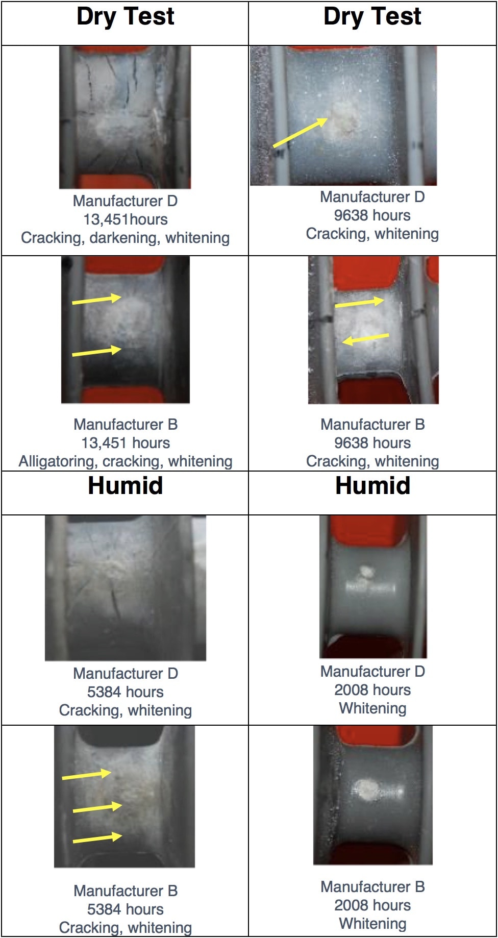
Eleven insulator designs were tested with a total of 124 new samples used at each test stage. Dry chambers ran to a maximum of 14,000 hours while the high humidity chambers to a maximum of 6000 hours. Fig. 5 shows images of two insulator designs over these different time intervals. Whitening of the polymer material was common for all manufacturers while cracking was observed on some but not all samples. Inclusion of moisture into the chamber accelerated degradation and cracking, which were observed with less test time, as seen in Fig. 5 as well.
Assessment Methodology
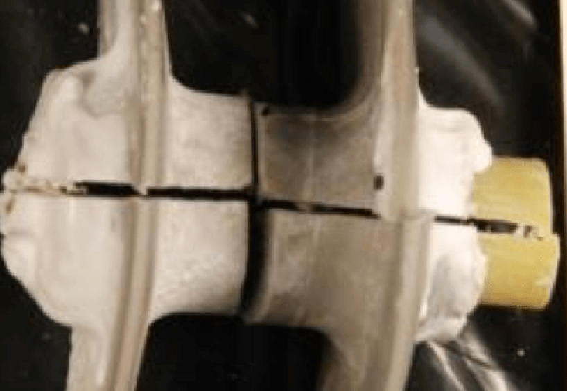
Samples were inspected visually and surface hydrophobicity documented periodically until the end of the tests. Samples were then dissected to assess depth of degradation by being cut in half through the midpoint where corona was present.
Visual Inspection
Insulator surface condition was assessed based on EPRI’s Visual Inspection Guide and a photo taken to record each sample at each inspection. As the rubber surface degrades from exposure to corona discharge, several features can be present simultaneously. Each surface condition identified was noted and documented.

Hydrophobicity
An important characteristic of polymer insulator technology is how the surface of the material wets. Surface wetting properties can be categorized as either hydrophobic or hydrophilic, following the method documented in IEC 62073.
Diameter Measurement
As a rubber surface degrades, filler material can break away resulting in reduced diameter. Diameters were measured once before the test and twice after the test at the locations where corona discharge exposure occurred.
Dissection
Insulator samples were dissected to examine the degradation identified on their surface and three parameters were documented:
1. Crack length;
2. Number of cracks;
3. Whitening depth.
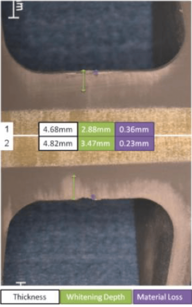
The surface was also inspected using a microscope and results photographed to allow digital examination of degradation depth (see Fig. 7).
Acceptance Criteria
In order for tests to be of value, their duration had to be long enough to generate degradation representative of that observed in service. The following minimum test durations are based representative degradation observed in the field:
• 15,000 hours (625 days or 1.7 years) for the dry environment;
• 6,000 hours (250 days or 0.68 years) for the 80% humidity environment.
For any polymer insulator to perform properly, its fiberglass core must be protected from moisture. Given this, maximum crack depth of 80% of the sheath thickness was deemed acceptable. Degradation of the rubber prior to cracking was observed as whitening or distinct discoloration, indicating a change in the rubber. Maximum allowable depth of whitening/degradation was set at 90% of rubber thickness.
Continued Research
EPRI is developing additional small-scale tests to address other stresses including:
• Impact of corona on end fitting
Such testing intends to assess effectiveness of end fitting design to control corona orientation as well as strength of the end fitting seal in the presence of water drop corona.
• Naturally occurring ultraviolet
This test intends to assess resistance of the polymer weathershed to UV exposure.
• Impact of handling
This test intends to assess an insulator’s ability to withstand damage from handling errors such as cuts, tears and impact.
• Impact of exposure from chemical contamination sources
This test intends to assess weathershed resistance to degradation from common chemicals found in linemen trucks.

Conclusions
Despite best efforts in optimizing design, polymer insulators are still at high likelihood of becoming exposed to corona sometime during their service lives. Unfortunately, current standards do not include tests that: 1. represent the corona characteristically found in service and 2. use actual polymer insulator samples. The test method proposed above addresses both shortcomings while also being of short duration and low cost.
• Results of this test method have shown to represent the degradation of in-service polymer insulators and are both repeatable and reproducible;
• Three modes of degradation associated with corona discharge exposure on in-service insulators were observed using the small-scale tests and results are considered representative of degradation observed in service;
• Rate of degradation in 100% and 80% humidity environments was from 2 to 10 times higher than in dry environments while humidity affected degradation rate differently among various manufacturers;
• Degradation modes and rates were consistent between test chambers and test sessions, thereby supporting the test being reproducible as well as repeatable;
• The test uses common off-the-shelf components and easily available components, making it low cost.
References
1 “Insulator Reference Book.” EPRI, Palo Alto, CA: 2017. 3002010140.
2 A. J. Phillips, D. J. Childs and H. M. Schneider, “Aging of Non-Ceramic Insulators due to Corona from Water Drops,” IEEE Transactions on Power Delivery, vol. 14, no. 3, pp. 1081-1089, 1999.
3 “Electric Field Modeling of NCI and Grading Ring Design and Application,” EPRI, Palo Alto, CA, 1999.TR-113977.
4 “Small Scale Aging of Polymer Insulators: Development of Small Scale Test Chamber and Insulator Evaluation Criteria.” EPRI, Palo Alto, CA: 2015.3002005690.
5 “Field Guide: Visual Inspection of Polymer Insulators,” EPRI, Palo Alto, CA, 2013.3002000968.
6 “Guidance on the Measurement of Wettability,” IEC, 2003.62073.