IEC standards for power cable systems up to and above 150 kV rated voltage are manufacturer standards and, according to experts, do not necessarily provide adequate recommendations for testing after-installation. IEEE 400 and IEEE 400.4 recommend partial discharge monitored testing using continuous or damped AC voltage (DAC).
This edited past contribution to INMR by Paul Leufkens of Power Projects Leufkens in the United States along with Prof. Edward Gulski and Rogier Jongen at onsite hv solutions in Switzerland, focused on application of DAC for after-laying testing and diagnostics of all types of transmission cables.


Reliable energy transport is fundamental to all on and offshore infrastructure and maintaining quality control regulations over newly installed as well as service-aged cable connections is of great importance. Key questions for any Transmission Grid Operator (TSO) in regard to reliable network operation include:
1. How best to detect poor workmanship defects in newly installed cable circuits in a sensitive yet non-destructive way?
2. How to perform non-destructive diagnostics of cable circuits already in service in order to determine their actual condition?
Based on present IEC standards for power cables up to and above 150 kV operating voltage, after-installation test protocols are limited to manufacturer minimum recommendations. But these do not necessarily always meet the need to keep failure risk during operation as low as possible. As a result, when considering responsible operation and asset management of transmission power cables, testing newly installed cable systems should be able to reveal:
1. Manufacturing related defects → less probable due to the high level of quality control in a factory;
2. Accessories parts delivery problems → more probable due to more diversification in supply chains;
3. Installation related defects → highly probable due to diversification in installation supply chains and practical difficulties when installing HV cable systems on or offshore.
Moreover, maintenance and diagnostic testing of cable systems already in operation should allow estimation of:
1. Operational damage as well as electrical and thermal over stresses → cannot be neglected e.g. transients and over voltages;
2. Ageing processes → depend on many operational and local factors e.g. presence of installation defects, load constrictions;
3. Remaining service life → goal of asset managers to keep CAPEX and OPEX at an optimal level.
Unfortunately, some traditional testing companies and contractors and also some TSOs refer to IEC procedures to ensure quality. But these documents (IEC 80840 & IEC 62067) were introduced 30 years ago, were highly influenced by manufacturers and tend to discuss factory-testing aspects. Only basic after-installation test are mentioned. Moreover, no guidelines are provided in regard to maintenance of cable circuits and also maintenance/diagnostic testing. In particular, IEC 60840 and IEC 62067 only recommend a ‘Go/No-Go’ decision as a result of breakdown during one of the following tests:
– Soak test with Uo at 24 hours; or
– After-installation test with 1.73 Uo or 2.0 Uo for cables with rated voltages up to 150 kV;
– After-installation test with 1.7 Uo, 1.4 Uo or lower for cables with rated voltages above 150 kV.
But these over voltage based destructive tests are not suitable to verify if there are insulation weak spots in a newly installed cable section. In case of an installation fault, breakdown occurs only in the case of an extremely serious defect (i.e. rarely). Yet in a situation where no breakdown occurs, presence of defects in accessories can still not be fully excluded. It is well known that breakdowns during such tests seldom occur and that the major reason for cable failures (i.e. some 30% of all failures after installation) are due to defects in or at the interface of joints and terminations. Most such installation defects result from poor workmanship. Moreover about 80% of insulation defects in power cables could be detected only using advanced diagnostics e.g. sensitive partial discharge detection. Considering the focus on reliability, the question is whether these failures could be avoided if TSOs maintain and update their testing procedures based on the latest developments. In this regard, the more recent IEEE 400 and IEEE 400.4, developed in co-operation between power companies, manufacturers and testing companies, can play an important role, in combination with other selected IEC documents. IEC 60060-3 and IEC 60270, for example, represent the state-of-the-art when it comes to modern, non-destructive methods for after-installation as well as for maintenance testing and diagnostics.
On-Site Generation of DAC Voltages
For sinusoidal voltages in the frequency range 20 to 300 Hz, close to the 50/60 Hz network stresses, testing is often conducted using a resonant test set (RTS). But an alternative is application of damped AC (DAC) voltages, including standardized conventional PD detection and analysis, which is now accepted worldwide for on-site testing and diagnosis of HV and EHV power cables. DAC technology was first introduced at the Jicable Conference in 1999 and now has some 20 years use in testing and diagnosing MV and HV power cables across the globe. Nowadays the DAC technology makes it possible to energize long lengths of power cable with a high capacitance with a low input power demand. The characteristics of the applied technology meet the specification of modern on-site testing systems:
• Lightweight modular system,
• Compactness in relation to the output voltage,
• Low effort for system assembling,
• Low power demand incl. long cable lengths,
• Low level of EM noises and possibility of sensitive PD detection and localization as well as dissipation factor measurements.
DAC testing for newly installed and service-aged cables is almost always applied in combination with partial discharge (PD) and dissipation factor (tan δ) measurements. Moreover, use of DAC voltages for testing power cables complies with relevant testing parameters derived from IEC, IEEE and Cigré standards and guidelines.
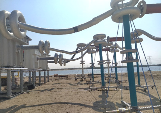
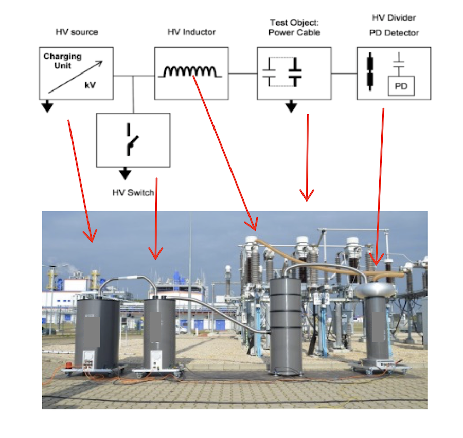
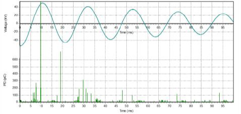
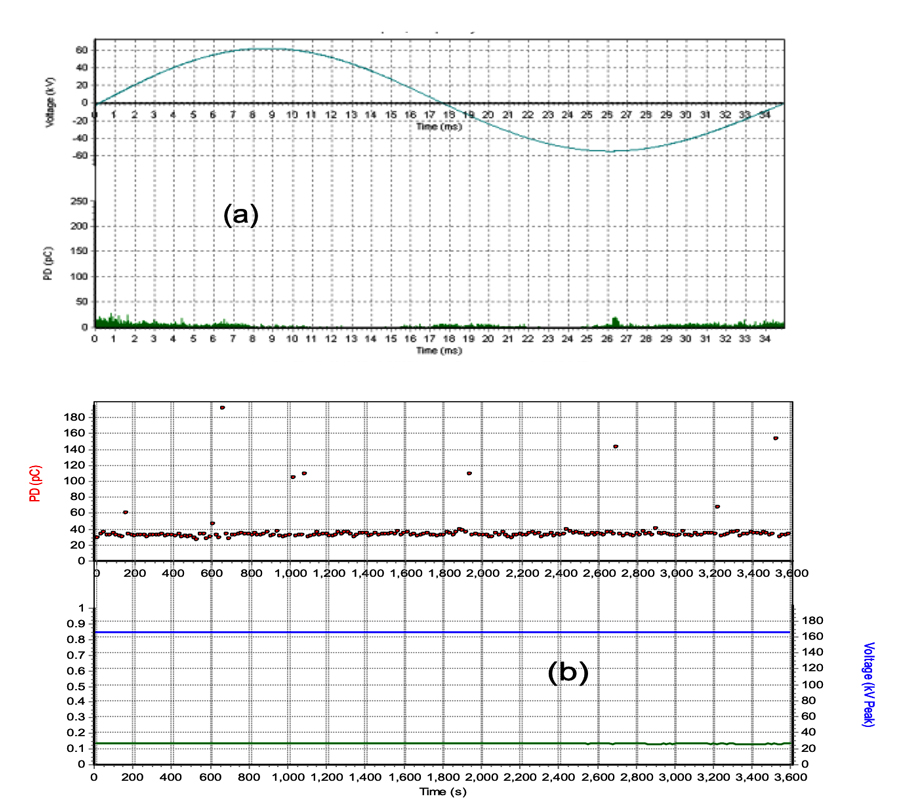
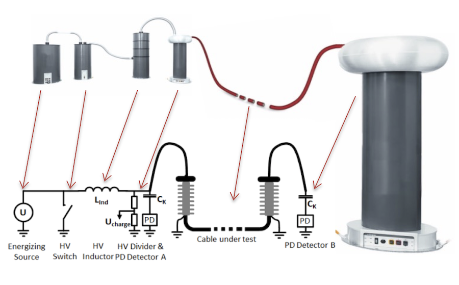
The system consists of a digitally controlled high voltage power supply to energize capacitive load of power cables with large capacitance, e.g. 10 µF (see Fig. 1). Energizing time depends on maximum available load current of the high voltage power supply, test voltage and capacitance of the test object but must remain less than 100 seconds. During a number of AC voltage cycles, PD signals are initiated in a way similar to 50/60 Hz inception conditions. In accordance with IEEE 400.4-2015, no DC stresses are applied to the test object and the DAC stress can be considered similar to factory testing conditions. Due to the continuous voltage increase and the immediate transition to the DAC voltage after the maximum test voltage is reached, no steady-state condition occurs. The low electric field strength in the insulation (typically < 20 kV/mm) and the short duration of bipolar stresses (i.e. less than a second up to tens of seconds) ensure no space charge accumulation (see Fig. 2).

Applying DAC voltage, sensitive PD detection and localization in power cables becomes possible. Using time domain reflectometry (TDR), presence of PDs in cable terminations, joints or cable parts can be localized (see Fig. 3).
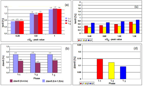
Moreover, dissipation factor, tan δ, can be estimated using the decay characteristics of the damped AC voltage. This can be especially valuable for detecting onset of ageing in paper-oil insulated cable insulation (see Fig. 4).
DAC Voltage Withstand Testing
According to IEEE 400.4, 50 excitations should be repeated followed one after the other in order to perform a voltage withstand test at the maximum test voltage (see Fig. 5). Considering time from PD initiation until breakdown and also shorter duration of the excitation and decaying characteristics of the voltage, DAC test results might differ from those obtained by continuous AC withstand voltage testing. Assuming that testing should not necessarily be destructive and that PD inception indicates the presence of defects, the difference in time to breakdown has to be considered an advantage of DAC testing.
Testing Long Length Cables
Sensitive detection and localization of PDs in long cable systems (e.g. 30 km) can be improved by performing measurements at both sides of the cable circuit. In the case of single sided PD localization, the overall PD pulse travelling distance is two times the cable length. But with double-sided PD measurement, the near end PD only has to travel to the far end to be detected there, thereby travelling only one time the cable length. This can improve detection sensitivity by up to 200%.
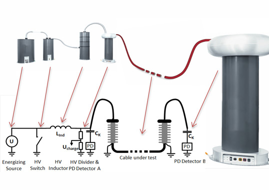
A damped AC system for energizing the cable system is used for such a double-sided measurement system (see Fig. 6). This dedicated solution uses a coupling capacitor with PD detector at the near end side and a second PD detector at the far end side (see Fig. 7).

On-Site Testing of HVDC Cables
Apart from HVAC cables, DAC technology is also suitable for testing HVDC cables. Installing an HVDC cable (e.g. submarine) is costly and challenging and the technical interventions for repair in case of faults are also costly and difficult. This makes effective commissioning testing even more desirable. Submarine power cable circuits have typical characteristics, including:
• high capacitances of HVDC cables that require extremely high power demand for conventional HVAC test systems;
• large number of (factory-installed) joints.
Testing with AC resonant test (ACRT) systems does not provide the desired selection criteria to obtain overall assessment of cable condition and requires great effort to generate the power requested on-site (i.e. numbers of ACRT sets). Compared to HVAC cable systems and accessories, HVDC cables are also designed differently. This could result in damage to HVDC cable and accessory insulation in case of defect breakdown under regular AC voltage over stresses. DAC testing, by contrast, makes it possible to energize very long lengths of AC as well as HVDC power cable with a high capacitance due to its low input power demand. In fact, only DAC voltage testing, including single- or dual-side partial discharge detection at the terminations, is able to test a complete installed HVDC cable length as well as detect and locate possible defects introduced either in the factory or after transport and installation.
On-Site Testing of Subsea Cables
Rapid growth in the number of offshore wind farms has contributed to continuing increase in renewable energy but repairing damage to such infrastructure can be challenging and costly. Subsea cable damage most often arises from two areas:
1. External faults such as caused in the open sea by anchor strikes or dragging fishing nets and due to erosion from jointer error or poor workmanship;
2. Poor planning at the start of the project coupled with inadequate risk identification, sub-standard design or deficiencies in how procedures are applied.
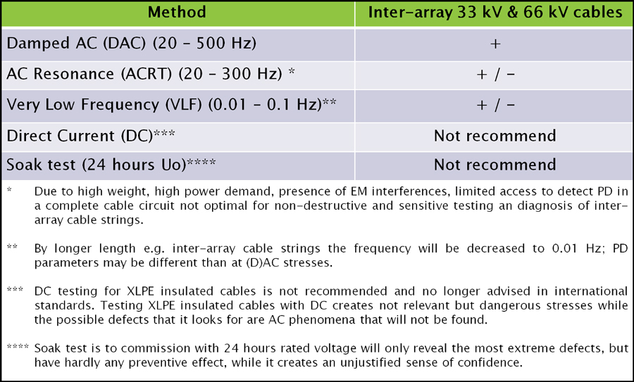
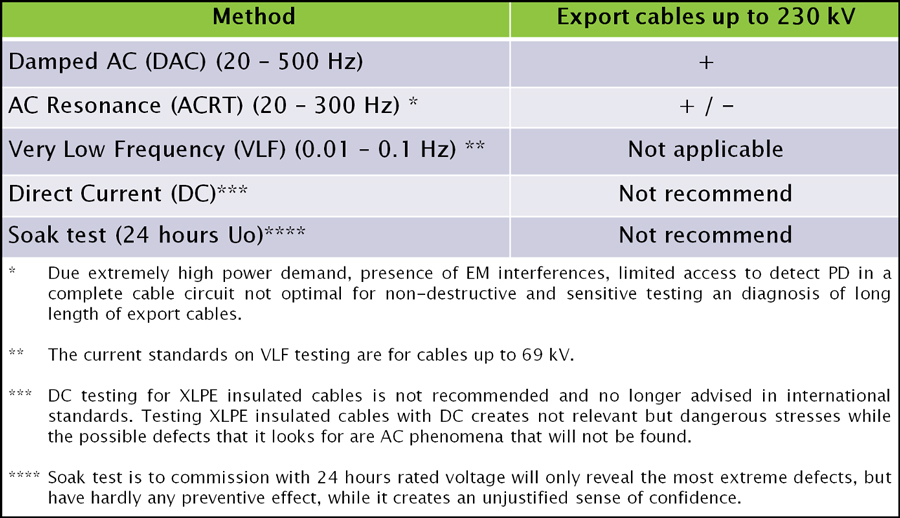
Indeed, each year the offshore wind sector reports on average at least 10 subsea cable failures. These incidents, while not frequent, still carry a high financial impact that continues to grow and accounts for about 77% of global losses by offshore wind farms. It has determined that some two-thirds of cable faults recorded in insurance claim databases can be attributed to contractor errors during installation – even if these do not become evident until a wind farms starts operating or is operational for a period of time. Several technologies are available to perform on-site testing of power cables. Tables 1 & 2 provide an overview of these techniques, including assessing key aspects of each. As can be seen, DAC monitored testing of offshore cables offers several advantages.
In general, an effective after-laying testing technology has to be suitable:
– for offshore testing, taking into account restrictions regarding e.g. size, weight, weather protection;
– to provide adequate information: voltage testing and fingerprinting (e.g. PD, tan δ) during the entire installation and operational process;
– to ensure reliable operation of inter-array cables;
– to provide contractors a basis for lowering risks during the warranty period;
– to allow service providers a solid basis for condition-based maintenance during operation.
Moreover, risk management criteria for contractors (e.g. a 5-year warranty), system operators and insurers have to be related to a quality control system applied during construction, e.g.:
a. Soak Test (non-monitored) Due to lack of information about operational reliability, this offers no warranty.
b. Non-monitored voltage withstand test only. Due to only locating extreme defects, this offers but limited warranty.
c. Monitored voltage withstand test (DAC resp. AC voltage test) with sensitive (PD, TD) fingerprinting. By providing complete information, this allows the fullest possible warranty.


Practical Case Histories
Offshore Inter-Array Cables
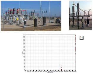
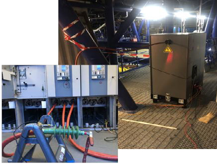
During a maintenance outage on a 15-year old 160 MW offshore wind farm, 10 complete strings of inter-array cables from the offshore substation to the wind turbines were DAC tested as part of diagnostic testing. For this purpose, switchgear in each wind turbine was switched in such a way that all the inter-array cables between the wind-turbines were connected to one another (see Fig. 8). The DAC test system was connected to the cable string under test via a special test adapter in the switchgear on the offshore substation (OSS). Total lengths of cable strings varied from 5.2 km to 9.5 km.
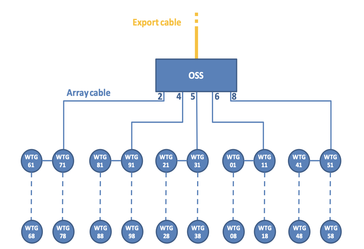
The benefit in this case was that the test system did not need to be transported between tests, i.e. all tests could be performed from the OSS (see Fig. 9).
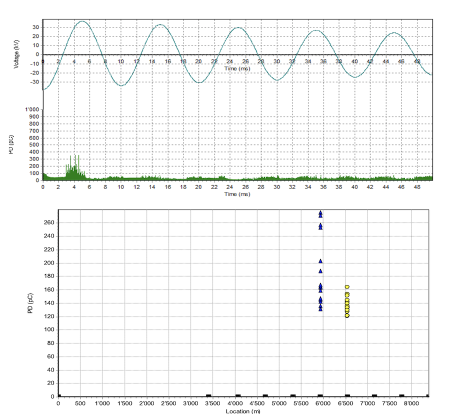
Partial discharges were detected and localized in an 8.4 km long string of inter-array cables between the OSS and 9 wind turbines. Each phase was individually tested using a damped AC offshore system with a DAC frequency of 100 Hz (i.e. total cable capacitance 1.85 µF). Maximum applied test voltage level was 1.4 U0. PD monitored withstand testing was performed of 50 DAC excitations at maximum test voltage. Although no breakdown was observed during the withstand test, as damped AC test voltage was increased starting from 1.4 U0, PD activity was detected in phases L2 and L3 of the string (see Fig. 10).
PD mapping revealed the PD concentration at 5.9 km in phase L3 and at 6.5 km in phase L2. These locations matched WTG locations where cable terminations enter the switchgear of a wind turbine. Based on these PD results (i.e. PD inception voltage and PD concentration at termination) it was advised to investigate/repair the location that showed PD activity or to further monitor the situation by repeating measurement on this string within a year. Since PD inception voltage in this case was above the nominal operating voltage of the cable, the operator decided to monitor PD behaviour and repeat the measurement in about one year during the next maintenance stoppage.

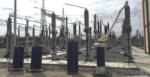
HV Transmission Cable
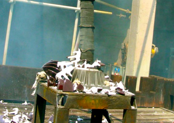
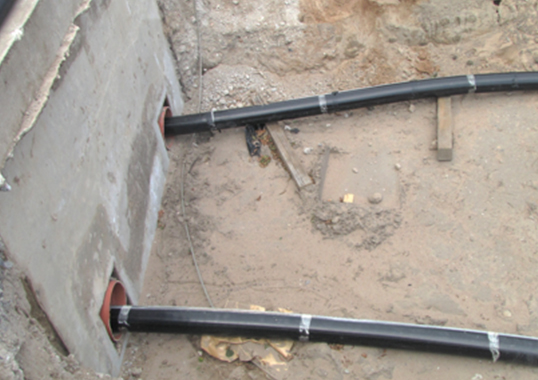
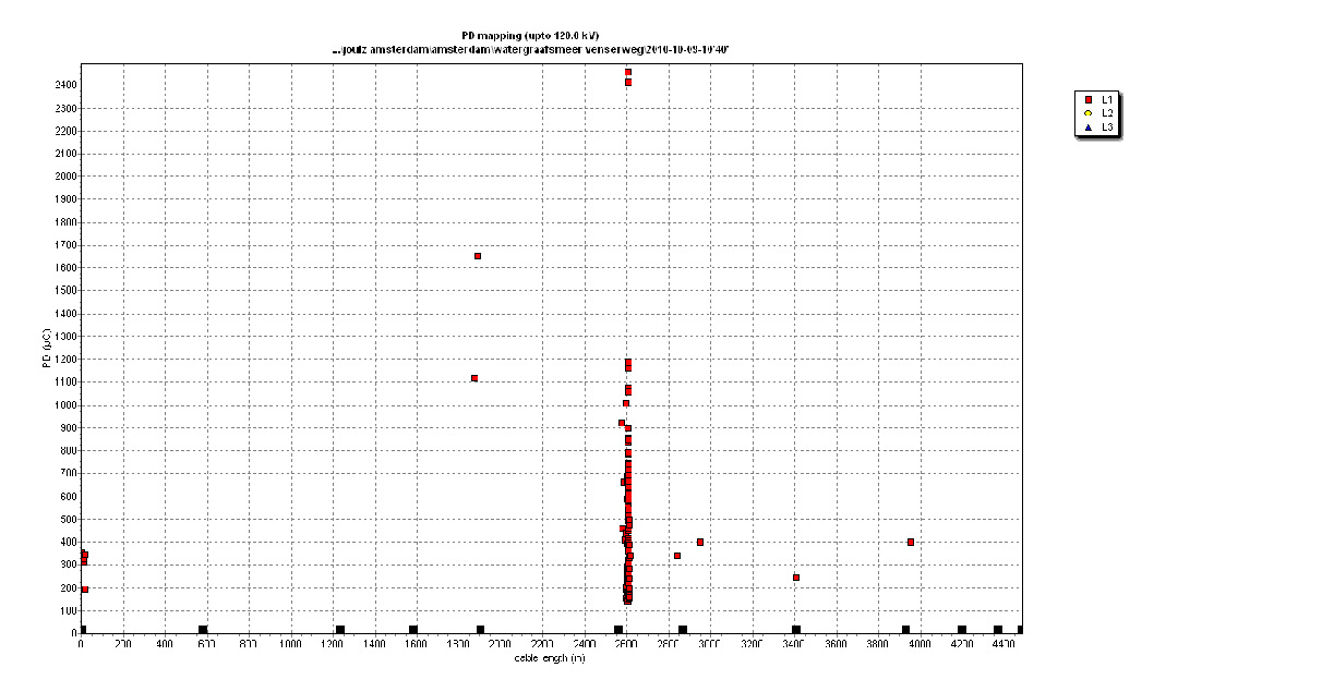
After-installation testing was performed on a newly installed 161 kV XLPE insulated underground cable circuit with length of 5.8 km (see Fig. 11). Maximum test voltage applied was 1.7 Uo and test frequency was 66 Hz. PD was detected starting already from 0.4 Uo in one of the total 6 phases (double circuit, see Fig. 12). Increase in test voltage resulted in increased PD activity. During the test, it was decided not to increase voltage above Uo and not to perform a monitored withstand test on this phase. Location of the PD defect could be determined with TDR analysis.
PD mapping revealed the concentration at 5.0 km and indicated their position in the cable (see Fig. 13), which was at the location of a joint. The other 5 phases fulfilled after-laying conditions and successfully passed the test. There was no internal PD activity in cable insulation or accessories and no breakdown occurred during tests on the other phases.
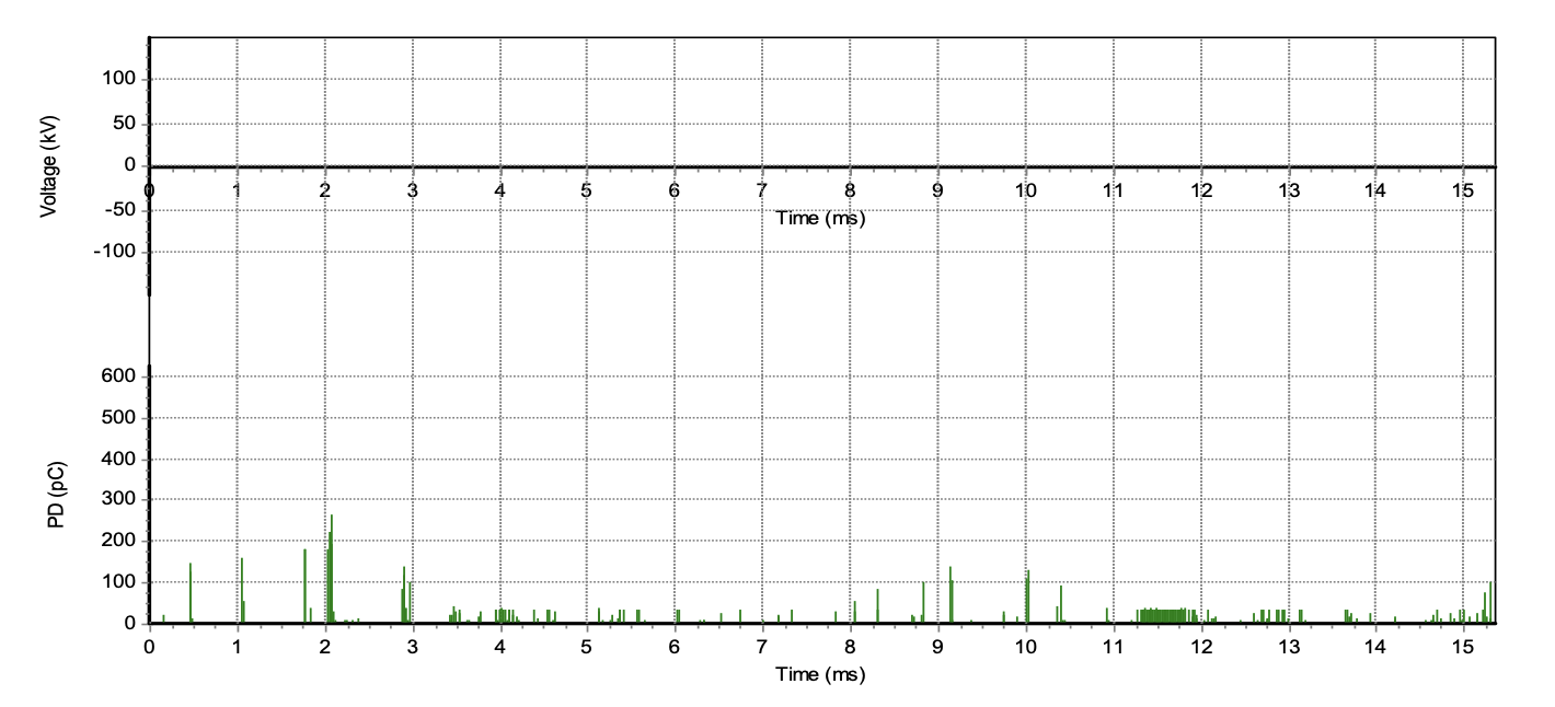
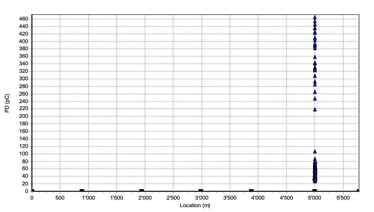
Concentrated PD activity below the operating voltage in phase L3 was sufficient reason to advise replacing or investigating the joint location. However, since this PD evaluation was not part of the original commissioning agreement, in this case the contractor decided not to immediately replace the joint. Unfortunately, after half a year subsequent operation, failure occurred in the joint of phase L3 at the 5000 m position.

Summary & Conclusions
Based on international experience over many years, the following conclusions can be drawn in regard to after-installation cable testing:
1. Present IEC 60840 and IEC 62067 standards do not fully cover the needs of modern TSOs by recommending over-stresses to create a breakdown in a newly installed cable section;
2. Performing sensitive non-destructive testing offers a solid basis for condition assessment and future life estimation of transmission power cables;
3. Damped AC (DAC) PD monitored voltage withstand testing is now common practice in many countries. PD measurements, including PD-pattern information and time domain reflectometry (PD localization), can help detect and locate discharge defects in power cable insulation and accessories;
4. DAC is a suitable technology to test long lengths of on- and offshore HVAC and HVDC power cables, with low on-site power demand needed and with sensitive PD detection and localization;
5. Case studies consistently demonstrate the value of applying damped AC testing, including PD detection and estimation of dissipation factor, to predict risk of failure prior to in service operation.
References
[1] F.J. Wester, E. Gulski, J.J. Smit, “Electrical and acoustical PD on-site diagnostics of service aged medium voltage power cables”, 5th International Conference on Power Insulated Cables, Jicable 1999
[2] IEC 60840: Power cables with extruded insulation and the accessories for rated voltages above 30kV up to 150kV Test methods and requirements;
[3] IEC 62067: Power cables with extruded insulation and the accessories for rated voltages above 150kV
[4] IEEE 400.4-2015: Guide for Field-Testing of Shielded Power Cable Systems Rated 5 kV and Above with Damped Alternating Current Voltage (DAC)
[5] E. Gulski, R. Jongen, R. Patterson, Modern Testing and Diagnosis of Power Cables using Damped AC Voltages, NETA World, Spring 2015
[6] R. Jongen, B. Quak, E. Gulski, P. Cichecki, F. de Vries, “On-site testing and diagnosis of long medium voltage cables”, Condition Monitoring and Diagnosis (CMD) conference, 2012, p. 659-662.
[7] R. Jongen, B. Quak, E. Gulski, S. Tenbohlen, “New developments in on-site testing of long lengths of (E)HV power cable”, Condition Monitoring and Diagnosis (CMD) conference, 2012, p. 149-152.
[8] M. Wild; S. Tenbohlen; E. Gulski; R. Jongen, Basic aspects of partial discharge on-site testing of long length transmission power cables, IEEE Transactions on Dielectrics and Electrical Insulation, 2017 , Volume: 24 , Issue: 2, Pages: 1077 – 1087
[9] P.P. Seitz, B. Quak, E. Gulski, M. Wild, F. de Vries, Long lengths transmission power cables on-site testing up to 500 kV by damped AC voltages, Jicable 2015
[10] Cigré Technical Brochure 610, Offshore Generation Cable Connections, 2015
[11] N. Hodge, R. Maurer, Power under the Sea, Allianz Global Risk Dialogue, Autumn 2014, pp. 26-29, available: www.agcs.allianz.com/assets/PDFs/GRD/GRD_02_2014_EN.pdf
[12] P. Tisheva, Cable failures account for most of offshore wind losses, June 2016, available: www.renewablesnow.com/news/cable-failures-account-for-most-of-offshore-wind-losses-528959
[13] P. Cicheck, Testing and Diagnosis of High Voltage and Extra High Voltage Power Cables with Damped AC Voltages, Delft 2018, ISBN: 978-83-952726-0-8