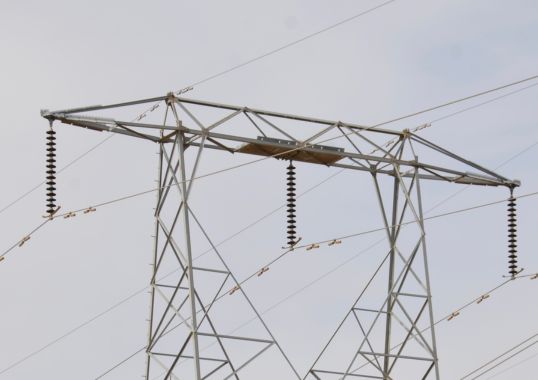
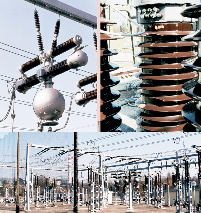
Selection of hollow composite insulators for application on equipment such as bushings, surge arresters, breakers and instrument transformers continues to increase worldwide. Indeed, where reduced weight or superior pollution performance are the main decision criteria, the majority of such apparatus is now being ordered equipped with this type of insulator.
Hollow core composite insulators are also a prerequisite in the move toward UHV DC since they permit creepage distances to be reduced compared to porcelain. This makes production of very long insulators more feasible given mechanical needs, especially in areas with seismic activity.
However, as discussed in this edited past contribution by experts at Hitachi Energy, safety ranks near the top of the list among market drivers toward composite hollow insulators.
Safety and reliability are increasingly important considerations for power utilities and are therefore one of the most important advantages offered by composite insulators for application on pressurized substation equipment. Insulators filled with compressed gas can store great amounts of energy, typically anywhere from 100 to 1000 kJ depending on size and pressure. To reduce risks associated with explosive failure, international standards prescribe minimum requirements for materials, design and construction as well as validation of these by full-scale testing and routine manufacturing inspection. Typically, such vessels must be subject to a routine pressure test to verify structural performance prior to delivery.


In the case of composite insulators, this routine test pressure is twice the highest pressure expected in service, i.e. design pressure or maximum service pressure (MSP). Failure or burst pressure of these vessels is generally required to be at least twice the test pressure. Four different elements of a modern design hollow composite insulator govern mode of failure in the event of an internal pressure overload:
1. The inner barrier layer or liner
This protects the load-carrying composite in the tube from corrosive degeneration products from the insulating gas, e.g. SF6. A new insulator must be able to sustain an internal pressure of at least 4 times the MSP with no visible damage to this liner.
2. Load-bearing composite in tube
The tube must be able to a carry pressure of at least twice the MSP without damage and at least 4 times MSP without rupture during validation tests under ambient conditions. The tube must also be designed to withstand all relevant mechanical, thermal and electrical loads over the entire service life.
3. Joint
This is the adhesive joint between the tube and the metal flanges.
4. Flange
The metal flange transfers mechanical loads to other parts of the assembly.

The insulator norm does not specify which modes of failure are or are not acceptable during a pressure test. Nonetheless, for safety reasons it is preferable that the failure mode is by leakage through the tube wall or by excessive deformations of the flange that lead to leakage. These are clearly better than failure of the adhesive joint.
For insulators whose tube fibers are wound either in or close to the circumferential direction, axial strength is low and sensitive to variations during manufacturing. In the event of excess pressure loading, such insulators can separate into two parts in a catastrophic manner. Therefore, such designs should be avoided. Failure in the adhesive joint is another undesirable failure mode. For this reason, this joint should be designed to have greater safety margin than other insulator components. To verify that insulators have safe behavior, even if loaded to failure, one optional test to consider is to pressurize to failure once type tests have been completed. Such failure should then ideally occur only by leakage through the tube wall.
Modeling can also be used to optimize design of the tube and adhesive joint prior to manufacturing prototypes and verifying these by means of type tests. Stress analysis is performed to determine the local stress state in a single layer of the composite and adhesive as a function of applied thermal and mechanical loads. Margin of safety is then assessed using conservative failure criteria given the strength parameters of the particular raw materials and manufacturing process.
It is important that these properties are determined for the material combination and manufacturing process of each particular supplier. This is because certain properties can prove sensitive to design details of the manufacturing equipment and process involved. Material properties determined to be relevant for insulators produced by one supplier cannot be expected to be valid for those produced by all suppliers. For this reason, performance of similar-looking composite tubes can also differ significantly among different manufacturers.

Shatter Test of HV Breakers
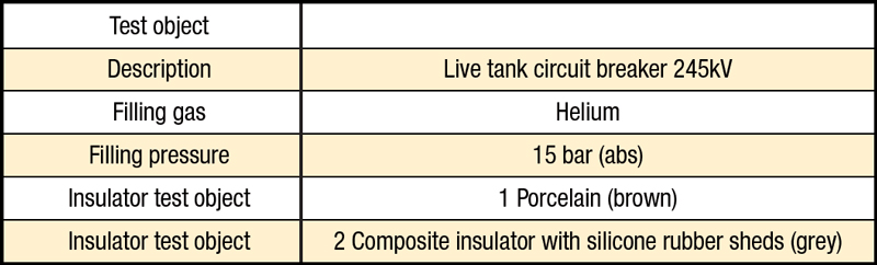
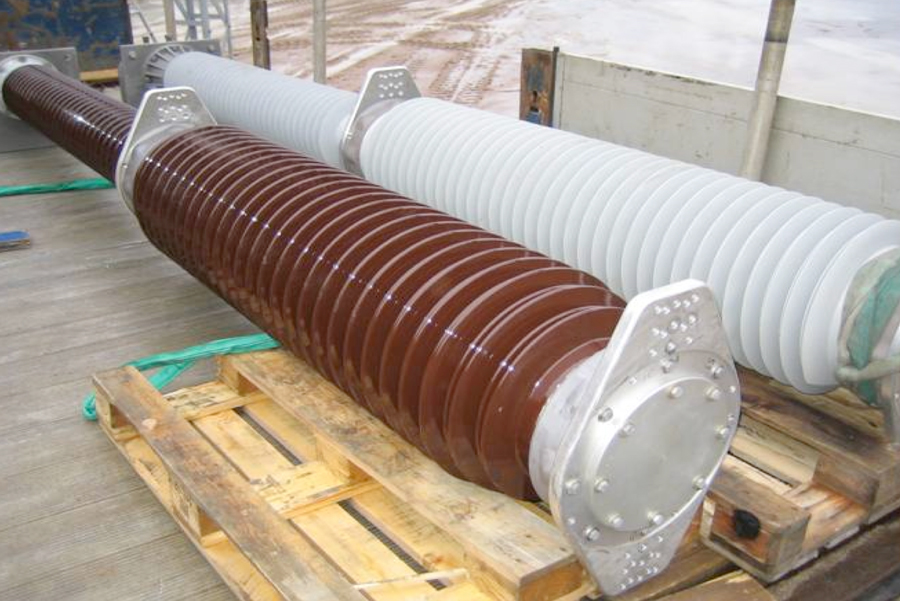
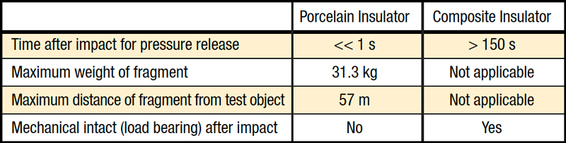
To compare failure modes of pressurized porcelain versus composite housings, a shatter test was performed on live tank circuit breakers equipped with both types of insulators. The different failure modes were then investigated. Table 1 provides data for the two test objects.
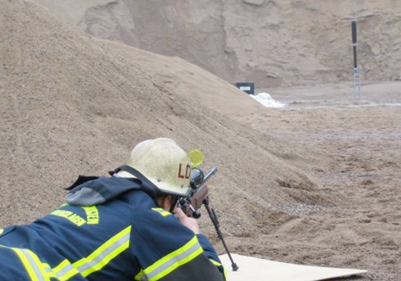
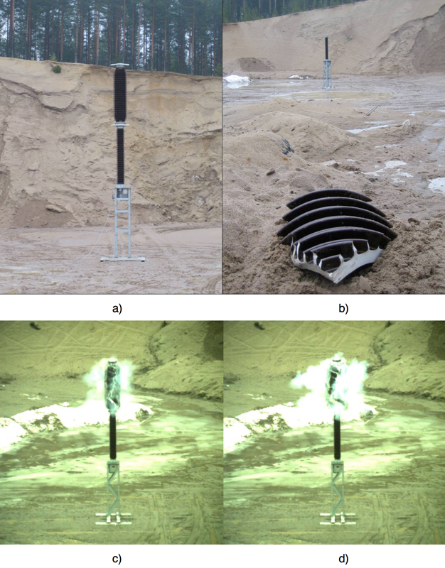
The methodology selected to investigate the different failure modes was by shooting with a 7.62 mm caliber hunting rifle (see Fig. 2) at a distance of 100 m from the test object. This simulated the possible effects caused by typical real-life events such as:
• internal fault/over-pressure in the equipment;
• external shock during transport, installation or maintenance;
• environmental influences e.g. earthquake, landslide, tornado;
• vandalism e.g. rock throwing, shooting.
The live tank breaker having porcelain insulators experienced failure with a violent explosion. The upper breaking chamber where the impact of the bullet occurred was completely destroyed and sharp porcelain fragments were ejected at high speeds. Fig. 3 illustrates the results before and after the impact. High-speed photos of the event are also shown.
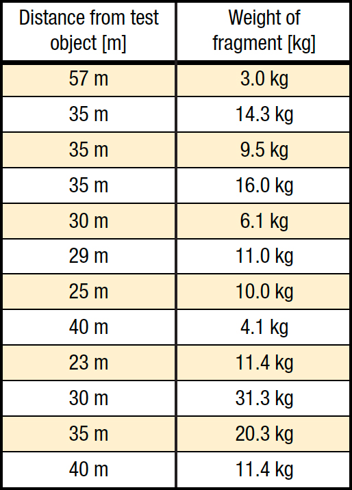
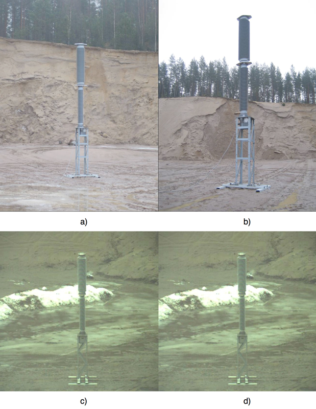
The main concentration of porcelain fragments landed in the range of 23 to 57 m from the test object and had a weight of between 3.0 and 31.3 kg (see Table 2). By contrast, test object 2 (i.e. the live tank breaker with composite insulators) remained mechanically intact after impact with the bullet. A small puncture occurred at the point of entrance, which was the upper breaking chamber. There was no launching of destructive fragments in the air. Fig. 4 shows the results before and after impact and includes high-speed photos. The time needed to release the overpressure through the puncture was >2.5 minutes.

Analysis of Findings
The photos in Fig. 5 below show these different failure modes. The porcelain insulator exploded into sharp fragments spread over a wide area. The composite insulator, by contrast, remained mechanically intact and with only a small puncture from the bullet.
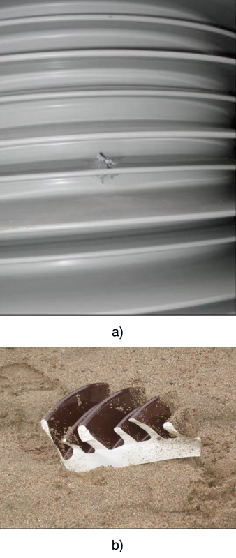
In the event of an internal fault/inner over-pressure or external influence such as vandalism, a porcelain insulator will experience violent failure (explosion) with dangerous fragments thrown about at high speed. The failure mode of a composite insulator, however, is by de-lamination/puncture with no launching of any dangerous fragments. There is therefore no possible damage to surrounding equipment and no danger to persons in the vicinity. This assures maximum safety for both personnel and other equipment at the substation.

Summary & Conclusions by Richard Martin
The late Richard Martin, one of the industry’s foremost experts on hollow composite insulators until his passing 10 years ago, summarized below his views on key aspects of the safety offered by hollow composite apparatus housings.
Perhaps the most basic motivation to specify composite housings is their inherent safety in the event of failure. Each year sees cases of costly material damage and even injury resulting from catastrophic equipment failures such as internal arcing, explosion, short circuit displacement of bus supports or seismic and other unexpected mechanical stresses. Vandalism and contamination flashovers only further contribute to the risks from sudden power arcs and failures of porcelain at a substation.
The requirements necessary to achieve a fully explosion-proof composite apparatus housing fall onto the FRP tube and end fittings assembly. Standards for pressurized housings describe severe tests such as pressure tests combined with partial discharge and routine tests at 10 bars. The burden of assuring an explosion proof housing resides on the tube’s special construction, including winding angle, thickness, resin-to-glass ratio and bonding method to the end fittings.
Insofar as seismic events, composite apparatus housings offer a level of performance that cannot be matched by porcelain. While certain complex designs involving porcelain could survive most earthquakes, these would typically be extremely heavy due to greater wall thickness and this implies higher cost.
At the same time, it should be stressed that superior mechanical and electrical withstand of composite hollow core insulators during a seismic event is not necessarily generic. Rather, it requires a good knowledge by the manufacturer of such factors as amplitude in three axes, duration, cycles per second, natural frequency of the affected apparatus, generated bending moments and allowed deflection. IEEE 693 provided excellent guidelines and testing techniques to evaluate apparatus destined for service in seismic prone areas. Indeed, the housing has to be specifically designed for the application. For example, the seal and tightness system must assure no leaks of oil or gas after shake table tests intended to simulate a seismic event.
The type of apparatus for which a composite insulator housing is intended places additional burdens onto their supplier in regard to maximum safety. In the case of high voltage disconnectors such as vertical and horizontal break devices, the tube designer also has to take into account the limited allowed displacement on the line side. There should therefore be increased rigidity but not at the expense of greater bending moments at the base fitting or a large increase in weight.
To assure true safety for application on circuit breakers, composite hollow core insulators must be designed to withstand possible arcing inside the SF6 insulated chamber as well as high temperatures of the end flanges and conductor. In the case of arcing in live tank breakers, designers must include a non-glass fibre liner to seal the vulnerable glass-resin matrix against any SF6 by-products. At the same time, the composite tubes used for such breakers (i.e. both support and chamber housings) need greater rigidity in order to maintain the alignment of electrodes in the arc chamber as well as external clearances. Dead-tank breakers have still more parameters which must be considered to assure the promise of complete safety offered by composite housings. The high current electrode can generate enough heat as to elevate the temperature of the flange-tube assembly beyond 100°C. Moreover, the internal gas pressure generated is sufficient to cause failure of this important bond