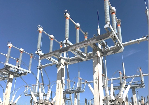
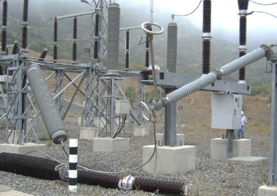
When delta-wye power transformers are installed in a distribution substation, the neutral is usually solidly grounded and needs no surge protection. This is because the transformer’s neutral is kept at the same potential as the substation ground grid by the solid ground. However, there are applications where, for specific reasons, a power transformer’s neutral can be grounded through impedance that can be resistive or inductive or even ungrounded.
In such cases, it is important to protect the neutral terminal from surges that can be transferred through the transformer. Since the transformer neutral is subjected to voltage stresses during fault or surge events that are much different from normal operation, the approach to surge protection is different than for other terminals of the transformer.
This edited past contribution to INMR by Michael Champagne examined how surges propagate through transformer windings as well as the different voltage stresses experienced by the neutral terminal. The goal is to assure more effective surge protection and arrester application of transformer neutral terminals.
Transfer of Voltage Surge Through Transformers
To understand how such voltage can develop between a transformer’s neutral and ground it is important to understand how surges are transferred from one transformer terminal to another. When considering how surges transfer from primary to secondary terminals of a transformer, Hileman explained that surge voltages appearing on secondary terminals from an incoming surge on the primary terminal have four components:
1. Electrostatic;
2. Oscillatory, induced by a corresponding oscillation from the primary;
3. Second oscillatory component produced in the secondary (and tertiary winding if one exists);
4. Electromagnetic
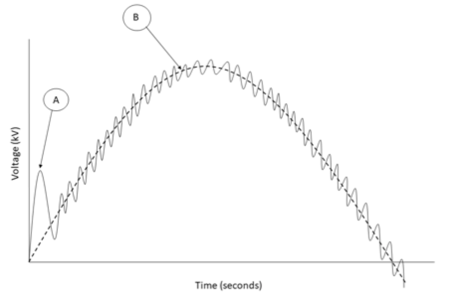
He determined these surge components by experiment and presented them in the diagram shown in Fig. 1. The initial sharp voltage spike is the electrostatic component (A). The electromagnetic component is the smooth sixty-cycle curve (B). The oscillatory components are shown by the smaller voltage oscillations superimposed on B. Magnitude and shape of the voltage transferred by the electrostatic component depends on:
1. Steepness of front (or time-to-crest) of the incoming surge;
2. Applied surge;
3. Nature of the impedance or load connected to the transformer’s secondary terminals;
4. Capacitance distribution within the transformer.

Electromagnetic Component
According to Hileman, when considering slower rise switching surges, the electromagnetic coupling effect is predominant. Oscillatory component surge transfers can be neglected because they are small compared to the magnitude of the electromagnetic component and can be eliminated by addition of several nano-farads of capacitance connected in shunt to ground at the secondary terminals of the transformer. The primary concern of the electromagnetic component produced by induction between the windings depends on turns ratio, leakage inductance of the transformer, impedances connected to the winding terminals and wave shape and magnitude of applied voltage. When calculating total transferred voltage, it should be assumed that arresters are connected immediately adjacent to the primary terminals of the transformer. These limit the voltage applied to the primary terminal to arrester discharge voltage. The crest of the arrester voltage is composed of a sixty-hertz voltage and a surge voltage, E1. The secondary terminal voltage is composed of a sixty-cycle voltage and a surge voltage, E2.
Total voltage seen at the secondary terminal of the transformer depends on time of the sixty-hertz voltage wave that E1 was applied, magnitude of E1, and transformer bank connections. In delta-wye transformers, the secondary will lag or lead the primary by thirty electrical degrees, depending on how the delta is arranged. Hileman derived and presented equations to calculate maximum total transferred voltage based on turns ratio, crest discharge voltage of the primary arrester, voltage shift angle of the transformer, φ, and transformer bank connection:
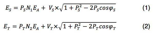 where:
N1 – is the ratio of secondary side, line-to-line voltage to the primary side, line-to-line voltage for two- or three-winding transformers
N2 –is the ratio of tertiary-side line-to-line voltage to the primary side, line-to-line voltage for three-winding transformers
φS , φT – are the phase displacement angles between primary and secondary line-to-neutral voltages, and between primary and tertiary line-to-neutral voltages, respectively
EA – is the crest discharge voltage magnitude of the arresters connected to the primary terminals of the transformer
VS, VT – are the crest magnitudes of the 60 Hz line-to-neutral voltage respectively on the secondary and tertiary sides of the transformer respectively
ES – is maximum total transferred voltage to the secondary side
ET – is maximum total transferred voltage to the tertiary
E1, E2, E3 – are the crest magnitudes of surge voltage at the primary, secondary and tertiary terminals respectively
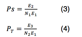
PS, PT – are scalar coefficients that can be estimated using Tables 1 and 2 for different transformer configurations.
Notes to Tables 1 and 2:
1 – values in parenthesis are for two-phase applied surge; values without parenthesis are for a single-phase applied surge.
2 – grounded or ungrounded.
These equations, derived for a three-winding transformer, are equally applicable to a two-winding transformer. In this case, only equations 1 and 3 need be used. In some instances, it is necessary to obtain the transferred surge voltage rate of rise to evaluate the required degree of lightning protection. This is best illustrated by the following example.
Example 1
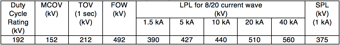
A 230/138/13.8 kV wye-grounded, delta autotransformer is assumed to be protected by a station class 152 kV MCOV primary rated arrester. The protective characteristics from the manufacturer’s published data indicate that the lightning impulse discharge voltage of this arrester, EA, is 440 kV at 10 kA. From the definitions:
N1 = 0.6 and N2 = 0.06.
From Table 2, the PS = 1.0 and PT = . From this data, calculate the maximum secondary surge voltage to be 264 kV, as shown below, and the maximum phase to ground tertiary voltage to be 28.497 kV.
Note: All arresters applied to each side of transformer should be identical. Arrester ratings not included on terminal nodes for drawing clarity.
From Equation (1): ![]()
From Equation (2): ![]()
Assume a 152 kV MCOV arrester, a 10 kA 8/20 μs current pulse with a crest discharge voltage (protective level) of EA = 440 kV.
From Table 2: ![]()
![]()
Therefore,
using Equation (1):
![]()
using Equation (2):
![]()
This example illustrates that, at power system frequency, voltage surge through a transformer is not always only the product of input voltage and turns ratio. The winding connection and phase displacement also have an effect.
For arrester coordination, it is necessary to select an arrester for the secondary that has a 10 kA discharge voltage greater than 264 kV. A 98 kV MCOV arrester (which has a 10 kA discharge voltage typically in the order of 283 kV) would be suitable. Likewise, if the tertiary is to be protected, it is necessary to select an arrester for the tertiary that has a 10 kA discharge voltage greater than 28.5 kV; 15.3 kV MCOV arresters are suggested. This MCOV is above the line-to-line voltage that the arrester will see if one corner of the delta becomes grounded. From surge transfer considerations only, 10.2 kV or 12.7 kV MCOV arresters may be used. Both have 10 kA discharge voltages above the calculated 28.5 kV surge transfer voltage and would coordinate for surges. However, if one of these lower rated arresters is selected, users must ensure that the delta not remain grounded for extended time periods that exceed the arrester’s temporary overvoltage (TOV) capability.
Obviously, the transformer BIL protective margins must be checked for all three windings and arrester selections. If this is a problem and the primary is known to be solidly grounded, the primary arrester could be selected as low as 140 kV MCOV and possibly the secondary arresters could have a slightly lower MCOV and 10 kA protective level.

Electrostatic Component
According to Hileman, the predominant effect is that steep fronted waves are only partially transferred through electromagnetic coupling – the same mechanism that governs transformer operation at sixty hertz. Electromagnetic transfer of steep fronted surges is less than 40 percent of the magnitude for higher frequency surges and hence electrostatic effects dominate. For electrostatic transfer at higher frequencies, capacitances between the primary and secondary windings and between the primary and tertiary windings can be described as a capacitive voltage divider. This work, presented by J. C. Das, shows that extremely high and damaging voltages can be generated on unprotected insulation. Das offers an example of an incoming surge with a 1.2 μs rise time with an arrester installed at the primary transformer terminal. The initial surge transfer through the transformer is a function of the transformer and secondary side external stray capacitance. The components of this capacitance are:
• Primary winding to secondary winding
• Primary winding to core
• Secondary winding to core
• Primary winding to transformer case
• Secondary winding to transformer case
• Winding layer to layer
• Winding to winding
• Phase to phase
• Bushing to ground
Das points out that this data may be difficult to obtain but is important to constructing a transient model. Although in all cases, the owner of the transformer will have to ask the manufacturer for assistance, Das uses typical capacitance values of core form transformers to calculate the initial voltage spike transferred to the secondary transformer terminals using a simplified model, as illustrated in Fig. 3.
Cbh is the high-voltage bushing capacitance
Cb is the secondary bushing capacitance
Chg is the distributed capacitance of the high-voltage windings
Clg is the distributed capacitance of the low-voltage windings
Chl is the distributed capacitance between the high- and low-voltage winding.
Combining bushing capacitances into winding capacitances allows the model to be simplified (see Fig. 4).
In his work Das presents typical capacitance values for a range of two-winding transformers, as shown in Table 3:
As seen, the range of values for transformer capacitance can vary over wide limits and the actual values for a specific transformer must be obtained from the manufacturer. Using the Das model, the initial voltage spike transferred through the transformer (from primary to secondary terminal) can be calculated. Consider, for example, a transformer that has primary arresters but no secondary arresters. The initial voltage spike seen at unprotected secondary terminals can be calculated using Equation 5.
![]()
where
Vls – is the lightning surge transferred to the secondary terminals
S – is the factor depending on the transformer winding
p – is a factor, which allows superimposition of lightning surge voltage over power frequency voltage
p = 1.05 for wye-wye transformers [4]
p = 1.15 for delta-wye transformers [4]
EA – is the surge protective level of the primary arrester
The factor S is defined by Equation 6.
![]()
where Cext is the external capacitance as seen from the secondary side of the transformer.
As stated, this model is a voltage divider and is best illustrated using an example similar to one presented by Das.

Example 2
A two-winding 50 MVA 230/13.8 kV delta-wye transformer is considered. The primary windings have a BIL rating of 900 kV and the secondary windings have a BIL rating of 110 kV. The transformer is installed with a low-resistance 400 A resistor. The primary winding is protected using the arrester shown in Table 4. The primary winding is well protected by this arrester because all of its protective levels are well below its 900 kV BIL rating.
The next step is to obtain the values of capacitance of the transformer. From Table 3, it can be inferred that Chl = 6 nF and Clg = 12 nF in this example. Cext can be neglected because the transformer is considered to be unloaded (i.e. worst case for surge). From Equations 5 and 6, the initial voltage spike at the secondary terminal is 188.6 kV and, with the power frequency superimposed, the peak is 208.1 kV, i.e. well above the 110 kV BIL rating of the secondary winding.
This model is not completely accurate since it has been greatly simplified, neglects all saturation and is highly dependent on capacitances whose values can vary greatly. Nonetheless, it still makes a case to install secondary arresters and also that having the correct values of capacitance is important. As Das points out, this calculation should be done using a transient analysis model. For these reasons, the next edition of IEEE C62.22 will not contain this example but rather strongly advise accurate modeling of the transformer using such software when considering electrostatic surge through a transformer.
Neutral Terminals
Having studied how voltage surges can be transferred through a transformer allows examination of how a neutral terminal differs in behavior from phase terminals. Phase terminals (primary, secondary and tertiary) are energized while the transformer is in service and have a predictable voltage, as measured to ground. If the transformer’s load is balanced, the neutral’s voltage will be at or near zero during normal operation. The only time there will be a significant voltage between the neutral terminal and ground will be if there is an unbalanced fault or a surge, as described above. If surge voltage can be transferred electrostatically from primary to secondary, it stands to reason that the neutral terminal, not solidly grounded, will also see a voltage surge.
Neutral terminals not solidly grounded are subject to temporary overvoltages caused by line-to-ground faults. Isolated neutral terminals can experience overvoltages due to the reflection of impulse voltages from the line terminals. Moreover, in cases where the transformer neutral is resonantly grounded, high switching overvoltages can arise at the transformer neutral and across the winding. These can occur when a double phase-to-ground fault is interrupted and the circuit left connected to the transformer line side has a small capacitance to ground. For these reasons, the transformer neutral that is not solidly grounded should be protected.
Approach to Protecting Transformer Neutrals
The neutral terminal should be protected by an arrester with characteristics selected according to the system conditions and the withstand voltage of the neutral. Two kinds of arresters are used: the same design as for the arresters used at phase-to-ground but with reduced MCOV; or special arresters for this purpose with reduced protection levels.
In selecting an arrester for protection of a neutral terminal, its TOV capability is particularly applicable because TOV requirements become a more defining factor than MCOV. This is because the neutral arrester has a small (typically less than a few percent of phase voltage) continuous operating voltage in well-grounded systems, except during switching events and ground faults. It is important to consider both the duration and the magnitude of the TOV when selecting the arrester. The overvoltage at the neutral is equal to system zero-sequence voltage during faults involving ground. Calculations using the method of symmetrical components are straightforward.
If the transformer power source is switched with a single-phase device or protected by fuses, voltage at the ungrounded neutral can become equal to system phase-to-neutral voltage for an extended period. This condition occurs when one fuse or switch remains closed while the other two remain open. Since the neutral voltage for this condition will generally be higher and of longer duration than the TOV due to ground faults, this should be taken into account whenever selecting the TOV rating for the neutral arrester.
The energy classification of the neutral-to-ground arrester should not be lower than that of the phase-to-ground arresters on the same wye winding of the transformer. The electrical characteristics of the neutral-to-ground arrester will then be the same as those of standard catalog arresters of corresponding MCOV.
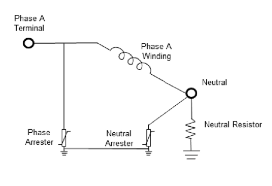
Care must be taken to use the BSL of the transformer neutral (not always as great as transformer winding BSL) when determining required arrester protective level. A protective ratio PRS = BSL (neutral)/SPL of 1.15 or greater is required, where SPL is the discharge voltage (usually at 1 kA for determining this protective ratio) or the gap sparkover voltage. When calculating protective ratios of the phase windings, it is important to note that each phase-to-ground arrester is in series with the neutral-to-ground arrester across the terminals of each transformer phase winding, as illustrated in Fig. 5. This is of particular importance when considering the case of surge impulses of opposite polarity between the phase and neutral terminals of the transformer. Therefore, when calculating protective margins as described above, the two arresters’ protective levels should be added and the sum used to determine the protective level across the phase winding.
When the transformer neutral is fully insulated to the same level as the wye-connected windings, protection can be achieved using arresters having a protection level equal to or lower than that of the phase-to-ground arresters. Due to the lower power frequency voltage between neutral and ground, the MCOV of the neutral arrester can be rated lower. Since the voltage between neutral and ground is zero in an ideally balanced system and less than a few percent in a typical well-grounded system, the MCOV of an arrester in the neutral point could be set nominally to zero. However, it does need to have a rating with adequate TOV capability. For the purpose of general selection, it is recommended to choose an arrester with an MCOV of at least 60% that necessary for the phase-to-ground arresters on the winding where the neutral point arrester is to be applied, assuming relatively long fault duration. Very short or very long fault durations may warrant selecting a different value, after taking specific TOV requirements into account.
Example 3
The transformer in Example 2 is a resistively grounded transformer 230/13.8 kV with 110 kV BIL rating on its secondary winding and 110 kV BIL on its neutral bushing. Catalogue data from typical arrester protective characteristics, as presented in Table 5, can be considered:
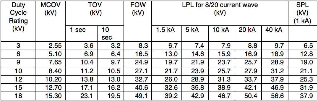
When selecting the phase-to-ground arrester for a resistively grounded transformer, it has to be noted that, when a ground fault occurs, the phase-to-ground voltage on the unfaulted phases will rise and approach normal phase-to-phase voltage for the duration of the fault. This is the referred to temporary overvoltage (TOV). Also, supposing the resistor has a 10 second rating, the transformer must be tripped before 10 seconds so that the 10 second TOV rating of the arrester can be used. This detail can be modified if protective relaying will clear a ground fault in less than 10 seconds.
In regard to the phase-to-ground arresters, the 12.7 kV MCOV arrester can be selected because it has a 10 second TOV rating greater than the normal phase-to-phase voltage. Now, given that the phase-to-neutral voltage is anticipated to be 8 kV for 10 seconds, an arrester should be selected with a 10 second TOV rating of at least 8 kV. Referring to Table 5, that choice would be the 7.65 kV MCOV arrester. This is near the 60% MCOV of the secondary arresters, as advised earlier. It can be seen that this arrester’s protective levels are all well below the 110 kV BIL rating of the neutral, thereby providing good protection. To verify that the protective ratios for insulation coordination are met for the secondary windings, protective ratios must be calculated, as prescribed in IEEE C62.22. This begins with adding the protective levels of each arrester and then calculating each protective ratio:
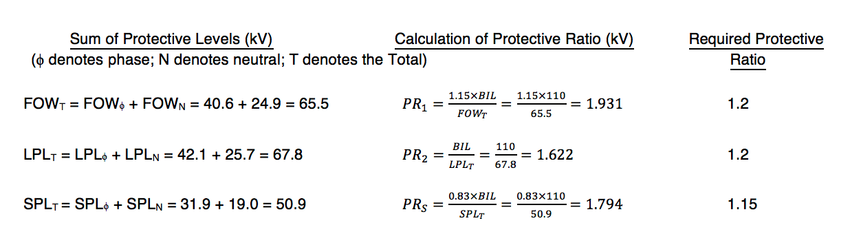
Since these calculated protective ratios are greater than those required by IEEE C62.22, the arresters chosen provide adequate protection of the secondary windings and the neutral.
When a transformer’s neutral insulation is less than that of the phase windings, the neutral terminal should be protected by an arrester with characteristics selected according to system conditions and the insulation withstand voltage of the neutral. This can be achieved using the same selection methods as for phase-to-ground arresters. In cases where intermittent ground faults occur repetitively (e.g. during abnormal environmental conditions), overvoltages of long duration and amplitude high enough to cause successive arrester operation could occur with consequent damage to the phase arresters. If such a situation is anticipated, it is beneficial to coordinate the arresters so that the neutral arrester operates prior to the phase-to-ground arresters. A higher energy neutral arrester can withstand the stresses and prevent damage to the phase-to-ground arresters. In this case, it is recommended that the SPL of the neutral-to-ground arrester be approximately 45% that required for phase-to-ground arresters if that neutral-to-ground arrester has high enough TOV rating.

Conclusions
Surges can be transferred through transformer windings and from one winding to another by electromagnetic and electrostatic means. High frequency surges are more affected by transformer geometry than by turns ratio and are unique to a specific transformer. Calculating these electrostatic transfers requires detailed study using a transient software product. Because surge transfer affects one winding to another, it also affects the neutral. Therefore, the neutral requires surge protection when not solidly grounded. The approach to apply arresters neutral-to-ground differs from that used to apply arresters phase-to-ground because the neutral has a much lower continuous operating voltage to ground during normal operation and behaves differently during abnormal conditions. In specific cases, the insulation rating on the transformer’s neutral terminal can be less than that of its secondary windings, which will affect insulation coordination calculations.
References:
[1] IEEE Std. C62.92.1-2017, Guide for the Application of Neutral Grounding in Electrical Utility Systems, Part I – Introduction.
[2] IEEE Std. PC62.22-2019, Draft Guide for the Application of Metal Oxide Surge Arresters for Alternating-Current Systems. This document is not yet completed.
[3] Andrew Hileman, “Surge Transfer Through Three-Phase Transformers”, AIEE Transactions, vol. II, part III, 1958, Power Apparatus and Systems, pages 1543-51.
[4] J. C. Das, “Surges Transferred Through Transformers”, 0-7803-7746-02-02-2002 IEEE, pages 139-147.