[inline_ad_block]
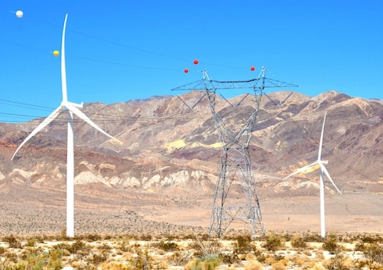
There is a relationship between trendy terms such as ‘renewables’ as well as ‘smart grids’ and electrical insulators, which most people view as just another piece of hardware in a power system. In the interests of protecting the environment and preserving valuable coal and oil resources for future generations, society has embarked on a major initiative to increase use of power from sun and wind. But the fact is that even if it were to suddenly be possible to generate immense quantities of electric power from these resources, it still could not be used profitably at present since there is insufficient capacity on most networks to transport this additional power to users. This unfortunate situation is fairly typical of most countries where transmission lines are running at or close to capacity. For example, a past article in a trade journal suggested that, in the U.S. alone, hundreds of GW from wind projects will need to be connected to the grid. Recent new line projects in places such as Belgium and Germany show that efforts are in fact now underway to address this issue.
While wind and solar power have each made giant strides over past years, it is important to put relative costs into perspective. Not long ago, the cost to produce 1 MWh energy from coal, nuclear, wind and solar in the U.S. stood at $44, $49, $70 and $160 respectively, although these figures will fluctuate based on market conditions. Still, the costs involved for solar and wind energy are tied to expensive equipment such as photovoltaic cells, solar concentrators, wind turbines and the large scale electronics needed to obtain the constant frequency AC output voltage to connect to a power grid. With growing use, wind and solar power will probably decline in cost. But there is still another impediment, namely that load centers such as big cities are usually far from the locations offering favorable wind and sun conditions. Moreover, particularly in the case of solar, the area needed to generate power is much greater than for conventional sources and not typically available near load centers. Yet another issue to deal with is that the times of highest power consumption, i.e. early morning and evening, are exactly when the sun and wind are not at their peak.
Many electric utilities are therefore forced to continue to use power plants that employ fuels such as oil and natural gas to satisfy peak demand, only because of their proximity to the load. So unless more cost effective bulk storage technologies are developed, wind and solar power will probably always remain at a disadvantage. It is this disadvantage that could be greatly offset by building more transmission lines, especially long ones that criss-cross different regions.
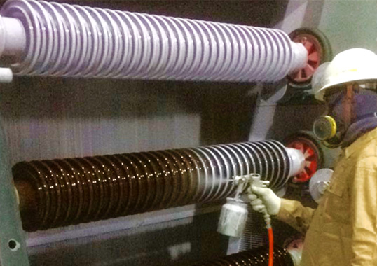
When all non-technical issues are finally settled, it seems clear that more UHV lines will need to be built, namely with voltages exceeding 500 kV AC and ± 500 kV DC. An alternative to new lines, of course, is to upgrade existing lines to enable them to carry greater power along current corridors. For example, the Pacific DC Intertie was upgraded from ±400 kV to ±500 kV DC during the 1980s. In many cases, only the insulators needed to be changed and this proved relatively simple with the cap & pin string configuration. In the case of the silicone composite insulators used along contaminated sections, these did not even need to be changed.
In North America, typical voltages are 69, 138, 230, 345 and 500 kV. The National Electricity Safety Code mandates that minimum clearances to live and grounded parts must not be violated. Still, a change in clearances for 138 kV systems compared to 69 kV amounts to only about 0.18 m. Similarly, going from 345 kV to 500 kV would require an additional 1.5 m (depending on desired BIL) – not really an issue for towers over 100 feet. Voltage upgrades create higher electric fields and these would need to be evaluated to determine optimal corona shielding and grading arrangements. Replacement of ACSR conductors with high temperature low sag conductors would permit higher current to be transported on the same right-of-way but might also require improvements in insulator materials and design. However accomplished, it seems clear that the benefits of clean power cannot be realized without significant investment in additional transmission infrastructure.
In regard to ‘smart grids’, different descriptions exist for this term. For example, the one used by the U.S. Dept. of Energy sees them as grids that function more efficiently and affordably while offering considerable societal benefits (e.g. less environmental impact). As such, increased use of ‘renewables’ is really built into the smart grid description. Increased efficiency is essentially the same as increasing reliability. For example, accoridng to the U.S. DOE, the power system is 99.97% reliable. This might seem good except for the fact that outages and interruptions still cost well over $100 billion each year. EPRI has estimated that 30% of outages are lightning related, so more judicious use of line arresters is one way to reduce the problem. Since such arresters are used in combination with insulators, it is also possible to make structures more compact, thereby providing the additional benefits of improved aesthetics and reduced electromagnetic fields.
It is also worthwhile remembering that insulators are one of the cheapest components of a line and basic principles of insulation coordination dictate that the insulator should fail first in order protect more expensive equipment at stations. Since most outages are associated with failure of an insulator, instead of waiting for them to occur, it should become possible to prevent them altogether by detecting impending failure. Therefore, rather than being just a mundane piece of hardware in the power system of yesterday, insulators could well play one of the key roles in power systems of the future.
Prof. Ravi S. Gorur

