Although line arresters (LSAs) have represented a fast-growing application in the electricity supply industry, there has been comparatively little direction on how users can best specify their desired performance characteristics. This edited past contribution to INMR by industry expert Jonathan Woodworth, while dated, still offers insight and recommendations on this process.


What is a Line Arrester?
Before defining what a line arrester is, it is useful to better clarify this terminology – especially since this power system component has been given several names over the years. The term has been divided in the IEC standard into two more precise categories: NGLAs (non-gapped line arresters) and EGLAs (externally gapped line arresters). In CIGRE and other such international forums, it is referred to as an LSA (line surge arrester) while in the IEEE regions it is often called a TLA (transmission line arrester) or just an LA (line arrester or lightning arrester). The focus in this discussion will be only on the NGLA.
Even though NGLAs have been in existence and covered by articles in such publications as INMR for the past 30 years, it is a component where service experience is still accumulating. In IEC standards, for example, there had been no definition or reference found that applies to the NGLA or transmission line arrester. In the IEEE standards, the term line arrester has been defined as a ‘type of arrester commonly applied to power systems to reduce the risk of insulator flashover during a lightning transient’. To this, it is worthwhile to add that the line arrester may also be used to protect insulators from other types of transients such as switching surges. A line arrester is generally not used to protect any equipment other than line insulators.
The NGLA Selection Process
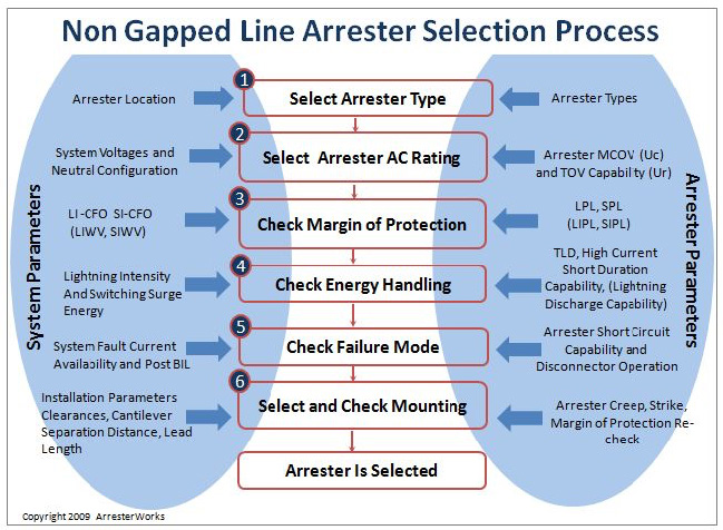
The process of selecting a suitable NGLA for the application can prove a challenge, even for experts, and starts by determining the characteristics of the power system as well as the location where the arrester is to be installed. Fig. 1 attempts to facilitate a description of this process and further steps in terms of NGLA selection, taking all key issues into consideration. At each step, system parameters are determined first and only then are the corresponding arrester parameters selected.

Step 1: Selecting Arrester Type
The selection process begins with choosing the type of arrester that best meets the overall needs of the application. Even though this is fundamentally the most important step, it is routinely left out of those procedures reviewed in the standards. For example, when the goal is to select a suitable arrester for a 33 kV sub-transmission line, there is no need to consider Class 5 arresters ordinarily installed on 400 to 800 kV lines. The initial choice can then easily be subsequently modified if any unexpected problems arise. The main actions as part of this first step include:
1. Identifying the approximate location of the arrester in the system;
2. Reviewing available arresters and their characteristics;
3. Making a selection of arrester type from among the different styles.
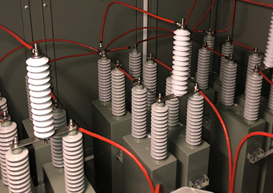
Another important consideration when selecting an arrester for a transmission or sub-transmission line is to consider the ideal type of external housing. Whenever possible, the first priority should be given to polymer-housed types (see Fig. 2), since they are lighter and more easily mounted than porcelain-housed units.
Step 2: Selecting AC Rating
Since most such arresters are energized with an AC voltage throughout their life, this step is critical. An incorrect AC rating can result in premature arrester failure and a resulting system outage. The definition of AC rating for an NGLA is Uc, namely the maximum AC voltage that can be applied continuously across the terminals of the arrester. In the case of NGLAs, this AC rating must be checked for temporary overvoltage (TOV) withstand capability and, if necessary, could be adjusted upward to meet these requirements. The initially selected AC rating is therefore generally a minimum value to be increased to meet other constraints as the selection process continues. Significant considerations in this regard are:
• Determining maximum steady state system line-ground voltage
This is defined as the nominal phase-to-phase voltage divided by 1.73 times the regulation error. On a transmission system where the nominal system phase-to-phase voltage is 760 kV, the line-to-earth voltage would therefore be 440 kV. Since all systems have some regulation error, this too must be taken into consideration. For instance, if the regulation error is 10%, then on the above system, the line-to-ground voltage could be 440 x 1.10 = 485 kV. The Uc of an arrester for such a system should be 485 kV at a minimum, even before TOV is taken into account.
• Selecting an arrester Uc that is equal or greater than this voltage
The general IEC practice, in this regard, has been to select a Uc that is at least 1.05 times the highest continuous line-to-earth voltage.
• Determining the maximum amplitude and duration of potential overvoltages
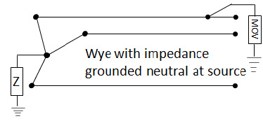
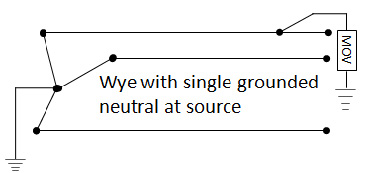
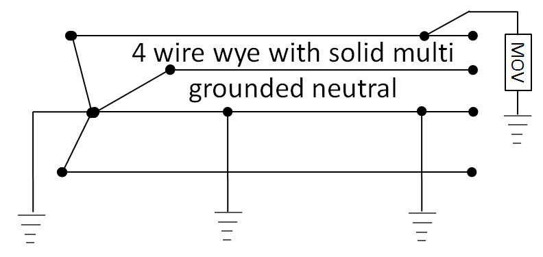
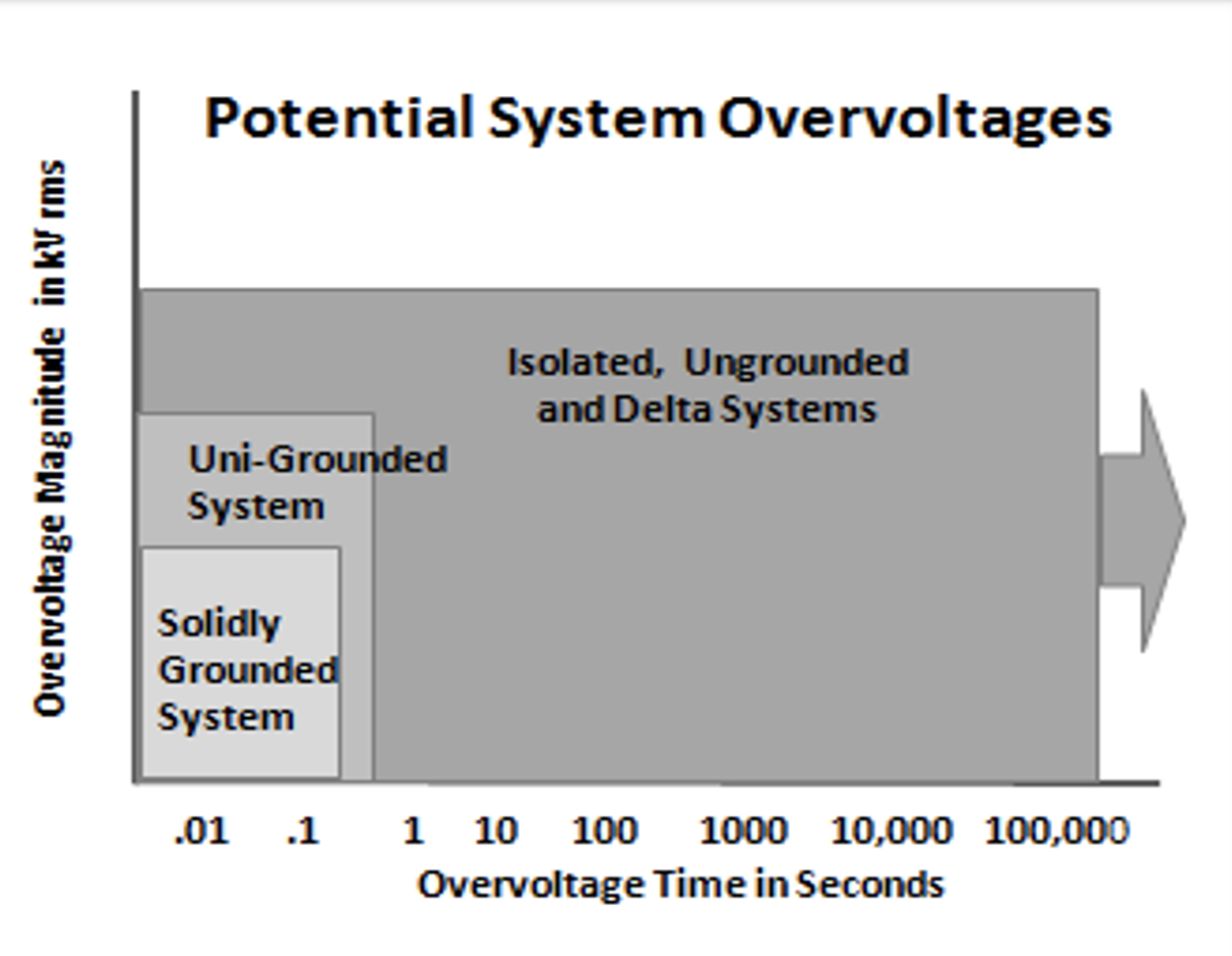
This is one of the most difficult steps in arrester specification since determining the amplitude and duration of temporary overvoltage events is not easy. In the case of arrester selection, the overvoltages of specific interest are the ones that occur due to an earth fault. During an earth fault on a 3-phase power system, the voltage on the unfaulted phase will rise to levels that can easily damage an arrester if not promptly removed by breaker operation. The neutral earthing configuration is the primary determining factor for overvoltage amplitude during this type of fault on the system. Figs. 3, 4 and 5 are examples of system configurations of importance.
For most distribution systems, the worst-case amplitude can be determined by the earthing configuration but seldom is duration clearly understood. Due to the lack of data for such applications, the durations are estimated based on system type. Fig. 6 gives an overview of these typical worst-case scenarios.
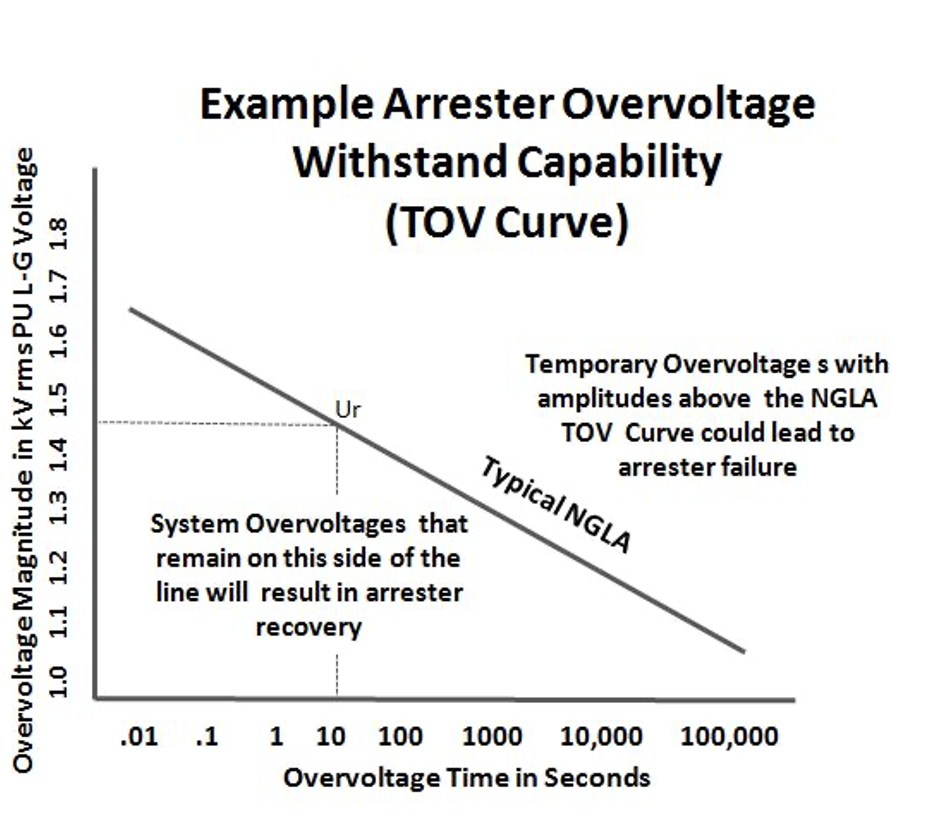
For transmission lines and substations, the amplitude and duration of overvoltages are much better understood and the worst-case scenario is seldom used. The systems in this case are usually modeled and the potential TOV level and duration are available from these fault current studies. Using these amplitudes and durations, one can compare them to the arrester TOV withstand curves, as shown in Fig. 7.
• Checking that the arrester selected earlier can withstand the overvoltages determined above using the arrester TOV curve.
Once the arrester Uc and Ur ratings are selected, the characteristics of that arrester will then be tested against any other constraints in the selection process. Should these other constraints require an increase in Uc or Ur, then the AC rating determined in this step will essentially be overridden.

Step 3: Check Margin of Protection
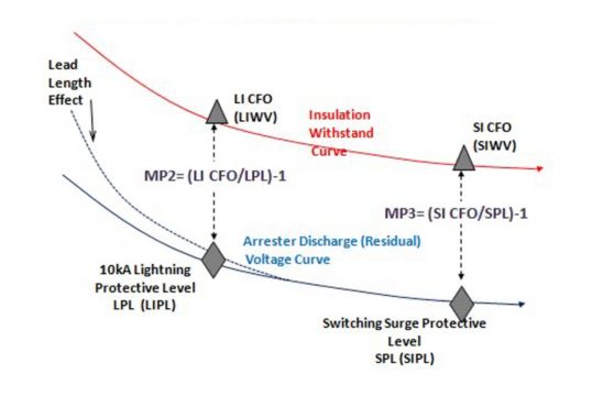
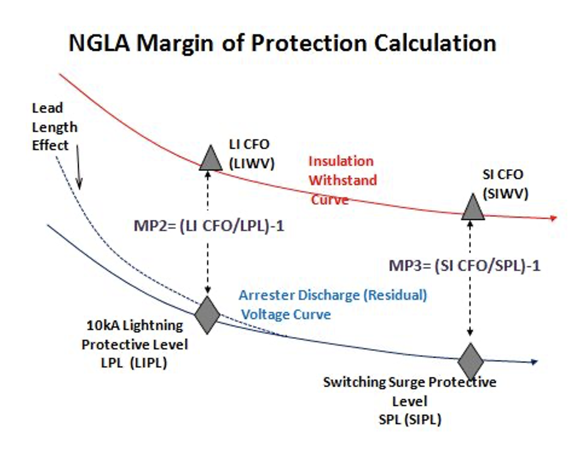
The fundamental purpose of a transmission line arrester is to reduce the risk of insulator flashover due to either switching or lightning surges. The margin of protection is then a standard means to evaluate the level of risk of flashover. If the arrester clamps the voltage at a fraction of the Critical Flashover Voltage (CFO) of an insulator, then this risk is quite low. Neither IEC nor IEEE standards make a recommendation as to what constitutes an adequate margin of protection for line insulators but instead recommend that the arrester residual voltage not be more than 80-85% of insulator BIL at stations. A graphical representation of margin of protection calculations is shown in Fig. 9. The fundamental aspects to the margin of protection selection process are:
• Determining insulation withstand characteristics
LI CFO (LIWV) and SI CFO (SIWV)
• Determining arrester protective characteristics
Lightning Protective Level (LIPL) and Switching Protective Level (SIPL)
• Determining if there is any lead length effect
• Calculating margin of protection
Lightning Protection Margin and Switching Protective Margin
Step 4: Check Energy Handling Capabilities
This is another important part of the selection procedure of an NGLA and requires proper understanding of the purpose behind the specific arrester application. Considerations that need to be taken into account in this regard include:
1. System with OHGW
If the arrester is to be used on a system equipped with an overhead ground wire, the energy requirements of the arrester are much lower than otherwise. This is due to the fact that most of the lightning current during a stroke is shunted to ground via the down conductor and only 10-20% flows through the arrester to the phase. If the footing resistance of the tower is high, more current will be diverted through the arrester and into the phase but even here most will still flow to earth instead of on to the conductor. For configurations less than 300 kV system voltage, a Class 1 arrester is all that is needed for ample reliability and protection. Using such an arrester for lightning protection where little switching surge energy is available is actually standard practice in both the U.S. and Japan. If a more conservative rating is desired for this configuration, a Class 2 arrester can be used, but is not strictly necessary. For systems above 300 kV, the class of arrester will likely be higher due to the energy demands of switching surges.

2. System without OHGW
If the NGLA application is on a system without an OHGW, the full lightning stroke is likely to pass through the arrester. Since a very low outage rate is desired, then a Class 2 or better arrester is recommended to protect this type of system. While Class 1 arresters are of course also an option, ensuring that the arrester has an extremely low risk of failure due to a high current stroke makes selecting a Class 2 or higher arrester the better choice.
3. Switching Surge Energy Considerations
If the NGLA application is to control surges generated during switching operations, the potential switching surge energy of the system needs to be calculated and compared to the energy handling capabilities of the arrester. For distribution and transmission systems below 230 kV, the potential switching surge energy of the system does not exceed that of a Class 1 arrester. Therefore, there is no need to consider higher energy ratings on such systems.
For systems above 230 kV, a precise energy dissipation requirement can be determined using transient analysis software. Alternatively, an estimate can be made using simple formulas found in either IEC 60099 or IEEE C62.22. IEC 60071 offers an excellent estimation of what magnitude of switching surges to expect on power systems as a result of normal energization operations. According to this standard, switching surges can range from 1.2 pu to 3.5 pu depending on system and response during the event. This translates into energies between 4-10 kJ/kV Uc, which is still well within the range of many arrester designs.
4. Lightning Impulse Discharge Capability Test
For arresters applied to systems up to 52 kV, High Current Impulse is the only means of classifying lightning impulse capability. For all Class 1-10 kA arresters, the designs are capable of withstanding 100 kA 2×10 µs impulse at least twice. For 5 kA arresters, this high current capability is reduced to 65 kA. For arresters applied to systems of 52 kV and above, a special test requirement and withstand capability is available to specifiers. Since 2006, all line surge arresters applied to systems above this level must be tested according to the Lightning Impulse Discharge Capability test outlined in IEC 60099-4 Annex N. This requirement uniquely tests the arrester with an impulse that crests in 200 µs and is sinusoidal. The test is unique because the arrester does not pass or fail but rather is placed into one of many available categories of withstand. A further unique feature is that the arrester withstand can be measured in either energy (joules) or charge (A-seconds). A Class 1 arrester is equal to about 1.4 coulombs and a Class 5 arrester approximately 8-10 coulombs of charge transfer. When selecting an arrester for protection of lines above 52 kV, this characteristic should therefore be considered.
Step 5: Check Failure Modes
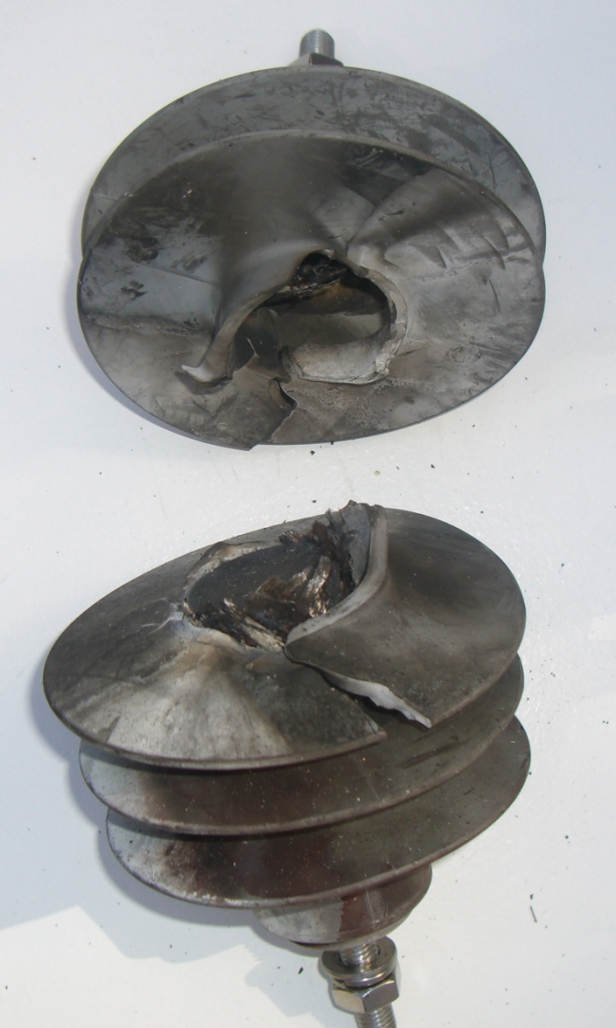
This is another important factor for selecting an NGLA, particularly if it is to be located near highways or public buildings. If the arrester is overloaded, it often becomes a short circuit to the system to which it is applied. If this happens, the power system will supply all potential fault current to the circuit, including to the arrester. When a shorted arrester experiences more power-frequency fault current than it was designed to handle, it could eject very hot components at high velocity and over great distances. Such fragmenting overload is clearly undesirable.
To ensure that this type of overload response does not occur, the short circuit current withstand capability of the NGLA needs to be higher than the available fault current of the system. This short circuit rating for all arresters is found on the nameplate as well as in the manufacturing literature.
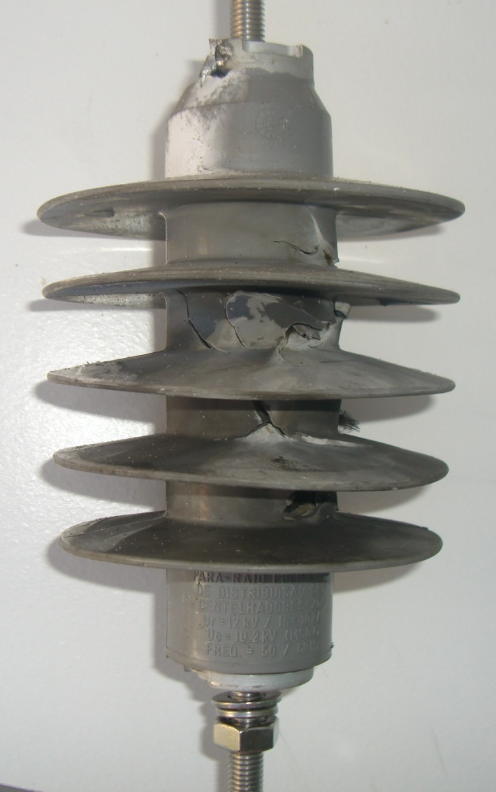
Typically, most distribution systems supply only 10 kA fault current, occasionally higher. Therefore the NGLA for distribution lines needs to offer a maximum of 10-15 kA rating. For transmission lines above 50 kV, the available fault current can be as high as 65 kA for solidly-grounded systems or as low as a few hundred amps for impedance-grounded or floating delta systems. After an arrester has been subjected to an overload, it should look similar to the examples illustrated in Fig. 10. However, should system ground fault current exceed arrester rating, the undesirable effects seen in Fig. 11 could well occur.
Basically, users need to know the available fault current on the system to which any arrester is to be installed and this data is readily available from the relay or from system analysis personnel.

Step 6: Mounting Considerations
Line surge arresters are stressed physically more than any other type of arrester since they are mounted on or near towers and exposed to the elements. High stresses are imposed by vibration, wind, torque and impact. For this reason, selection of mounting components is important and often one of the most difficult parts of NGLA selection. Also, since there are so many possible tower configurations, the mounting requirement for each installation is unique. Following are some specific features to consider in this regard:
Vibration
Presently there are no standard tests to determine if an NGLA can withstand vibrations found at tower tops and on conductors. It is therefore advisable that users discuss this with the arrester suppliers.
Disconnector Strength
If the NGLA is equipped with a disconnector, it is essential that mounting does not stress this component beyond its capability. If the arrester is to be mounted with the disconnector in any way other than the weight of the ground lead, this should be discussed with the supplier. While some disconnectors are designed for this type of stress, not all.
Lead Swing
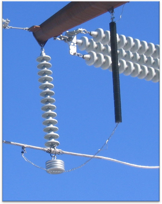
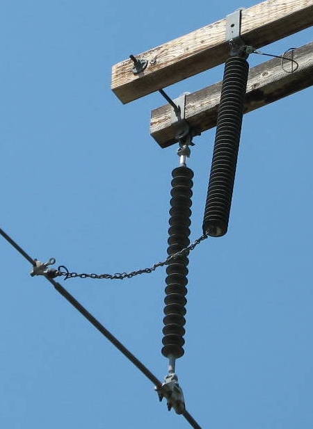
This is one of the biggest reasons for NGLA problems since a swinging lead can not only break itself, but also transfer mechanical stresses to other nearby components. Again, there is no standard for this issue so it must be discussed with the supplier. One solution often used is to string the lead through a chain that reduces the frequency and amplitude of any swing as well as reduce direct strain on the lead itself. Fig. 12 shows this arrangement.
Bird Droppings
If the NGLA is to be mounted where it is subject to possible bird droppings, the same precautions are needed as if it was an insulator.
BIL Restoration
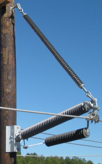
Once any NGLA has been overloaded and failed, it should be mounted in such a way that it will disconnect and allow full system BIL to be restored. This is best accomplished by mounting the arrester so that it or its lead will swing out of the way should it become a short circuit. Fig. 13 illustrates a horizontal mounting that is effective in BIL restoration.
Summary
Once any specifier has completed all six steps of the NGLA selection process discussed above, they will likely have chosen the optimal arrester for the needs of the application. There may be times that this process will need to be repeated before a final decision is made, but systematically going through all these key considerations guarantees that the NGLA selected will enhance the reliability of the power system to which it is applied.