Svenska kraftnät (Svk) is the transmission system operator in Sweden and has approximately 200 substations at 220 and 400 kV. The majority have been built several decades ago and many will be refurbished or rebuilt with new stations within the next two decades due to a change in demand with the ongoing energy transition. This puts great demands on the engineers to ensure continuous quality assurance when a large-scale building of substations as well as refurbishment of existing ones is foreseen.
Svk has written in their technical specification that all apparatus should be of composite material (except earthing switches) since more than 20 years, but all station post insulators should be of porcelain. Thus, porcelain is first choice when it comes to station post insulators but composite might be used when no feasible technical solution is available.
A standardized substation is built by two busbars and connecting transmission lines are entering through gantry towers in the middle of them. Disconnecting breakers are used to separate the two busbars, one on each side of the gantry tower entry. This is the most common station layout at Svenska kraftnät, however, there are plenty of other designs as well. Station post insulators are used hanging in the gantry towers, standing holding the busbars and standing holding jumpers in the bays.
This edited contribution to INMR by Peter Sidenvall of I2G in Sweden, in collaboration with Pernilla Sahlén, Armin Taheri and Kjell Andersson of Svk, looks at policies and experience when it comes to selecting and inspecting quality of station post insulators.

Composite Insulators
There was a gap of approximately 7 years when the requirement was composite types for all insulators within substations. No further requirements were stated regarding composite insulators. More than 1000 composite station post insulators were installed during the previously mentioned period, and spread to approximately 30 different substations. The majority of these have no protective devices but, in a few substations, grading rings have been installed with the insulators. The majority of these will be replaced with porcelain during the next 2 years, but some will remain in service during the technical lifetime of the substations.
Porcelain Insulators
Porcelain insulators are the first choice when it comes to post insulators. A few more requirements than the IEC 60168 are stated in Svk’s technical requirements. Such as requirement of corona free station, meaning that a corona ring is necessary to fulfil this requirement. Furthermore, a requirement limiting the amount of quartz in the porcelain is stated.
Quality Issues Found
Many different quality issues have been found during service inspections within Swedish transmission substations. Many of these are not connected to the specific insulator technology (i.e. porcelain or composite) but rather to overall knowledge, quality control in design, manufacturing, handling and installation practices. Moreover, there were a range of different findings during quality control either at the construction site or during factory acceptance testing at the manufacturer.

Findings from Factory Acceptance Testing (FAT)
As stated, Svk is refurbishing and building new substations in a scale never seen before. This requires a lot of new insulators and since lead times can be several months instead of weeks as earlier, new manufacturers (previously not used by Svk) have been used. Thus, the focus has been on quality control and related FATs, which revealed many quality issues.
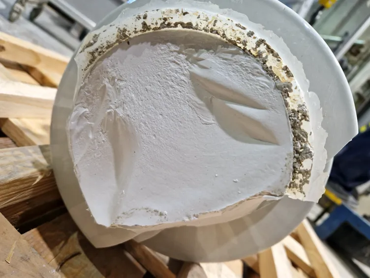
End Fittings
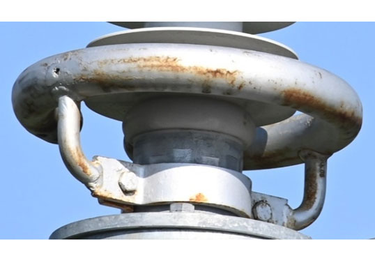
Several end fittings have been found with no height difference and where the water outlets will not work properly. This type of faults has not been addressed by any requirements in the past but gives an indication of the overall quality control of the manufacturer. An example is shown in Fig. 1.
Visual Examination of Porcelain Body
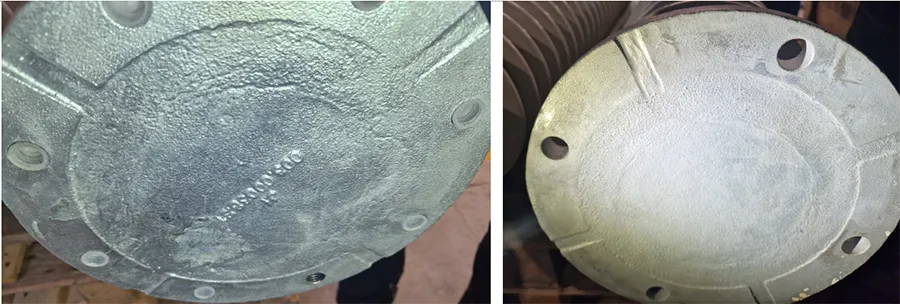
During the visual examination both inclusions (sand particles mostly) and glaze repairs were found several insulators. Example of both glaze repair and inclusions are shown to the left in Fig. 2. Furthermore, were a few damages found on the core of the insulator body, shown to the right in Fig. 2.

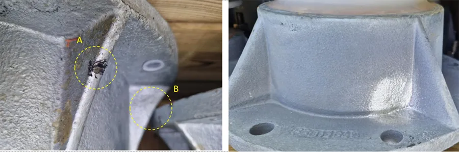
Mechanical Failing Load Test
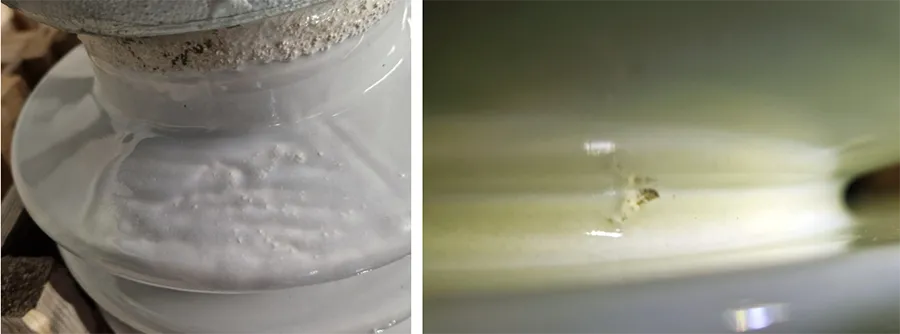
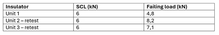
More than once have the first unit failed to exceed the limit in the mechanical failing load test. One example is presented together with retesting of two extra insulators in Table 1. A photo from the fracture of the first unit is shown in Fig. 3.
Findings During Quality Control at Site
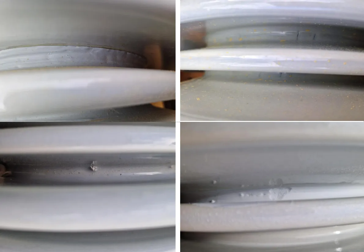
The quality control at site is a visual examination of the insulators. During this quality control, mainly performed by the contractors who will install them, the findings are quite many. First is how the insulators are transported in the crates. To one site the insulators came in crates without proper internal fixing. Thus, had some damages evolved from the end fittings rubbing each other, shown to the left in Fig. 4. Rather large areas of repairs of the end fittings have been found as well, shown to the right in Fig. 4. It should be noted that these types of findings are usually ok with all Svk’s existing suppliers of insulators.
On the insulator bodies cracks, chips, inclusions and glaze repairs have been found, shown in Fig. 5.
Findings in Service
During service inspections several common findings have been made. Many of these findings are easy to learn from and improve internal routines to avoid in the future.
Bolts & Nuts
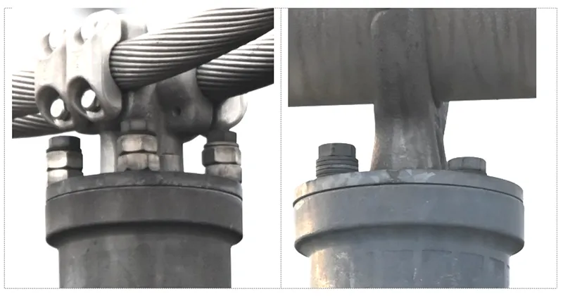
The design of connection plates and conductor arrangements can vary from substation to substation. This will unfortunately cause unnecessary corona activity and corrosion of the bolts and nuts. Examples of too long bolts and poor electric field design of the bolts are shown in Fig. 6.
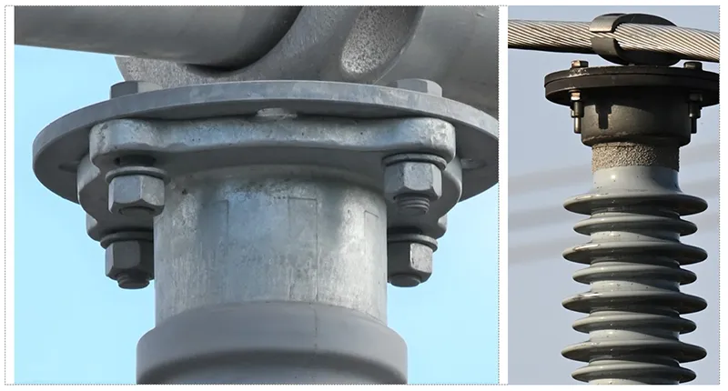
Moreover, it is not uncommon that contractors use “special” solutions when facing problems on site. When having too long bolts, extra washers or bolts as distances might be the solution of the day. Examples of this are shown in Fig. 7.
When the type of solutions as shown in Fig. 7 is found it is time to be careful. They will not only protrude and might cause corona activity, but it will be impossible to guarantee a specific tightening torque. Resulting in loose bolts after a few years and in worst case drop of jumper or busbar. Examples of loose bolts are shown to the left in Fig. 8 and damage on the surface of an insulator from a loose jumper is shown to the right in Fig. 8.

Protective Devices
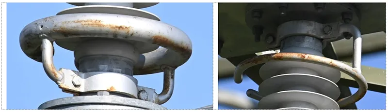
Protective devices on station post insulators are a necessity at 400 kV. All types of station post insulators will cause continuous corona activity at this voltage level, resulting in corrosion on the end fittings and audible noise. The corrosion might lead to further damages on the insulator, but not necessarily. Continuous corona activity towards the insulator body, will also erode the glazing of the porcelain, and if extremely severe it might start to erode the porcelain.
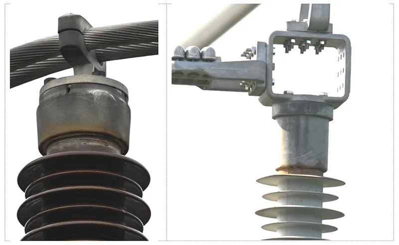
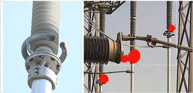
When it comes to protective devices on composite station post insulators, they are even more important. To keep the dielectric properties intact over years in service it is of importance to respect and fulfil electric field criteria presented in several papers over the last years. If not using protective devices at 400 kV, composite insulators will develop severe damages, ultimately leading to failure prematurely. Examples of corroded end fittings are shown in Fig. 9.
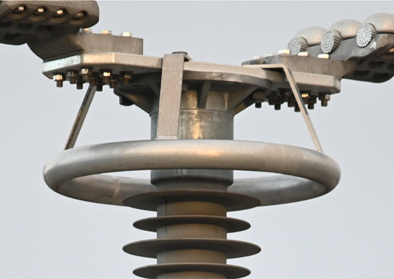
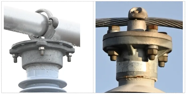
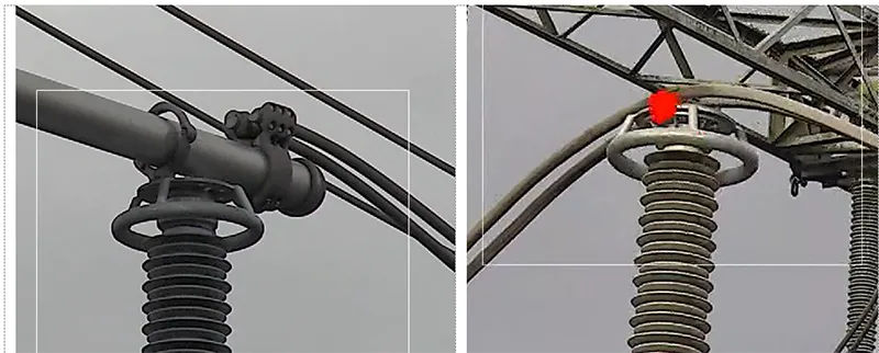
A simple corona ring will significantly reduce the electric field stress on a station post insulator. Examples of with and without protective device, from two neighbouring bays within a substation, is shown in Fig. 10.
The design of the ring needs to be fit for purpose, which is not always the case. Example of a too small rings leading to continuous corona activity and corrosion is shown to the left in Fig. 11. The direction of the ring is not always correctly installed, shown to the right in Fig. 11.
Moreover, a protective device intended for an insulator in one position might not be feasible for the same design of insulator in another position, e.g. when holding the busbar versus holding a jumper in a bay. A comparison with UV-camera is shown in Fig. 12.
Quality of Protective Devices
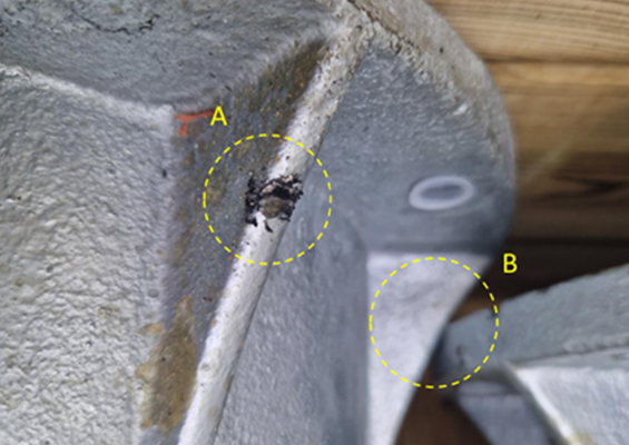
The quality of the protective devices might not be as expected. Poor fillings of drain holes, unsatisfactory welding and rough surfaces are common issues when receiving materials. Examples of lack of galvanization are shown in Fig. 13 resulting in corrosion after a few years in service.
Different Positioning of Station Post Insulators
The different positionings of the post insulators will affect electric field strength on the end fittings and, if installed, protective devices. A post insulator in a bay will face significantly higher electric field compared to a post insulator holding the busbars. The busbars at 400 kV are usually 250 mm diameter and will help with the electric field grading in the vicinity of the end fitting.
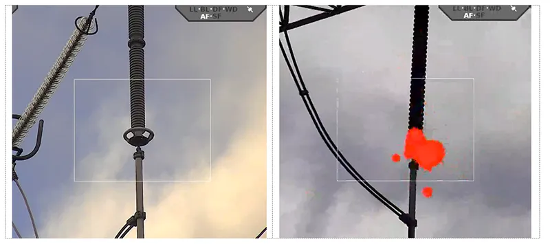
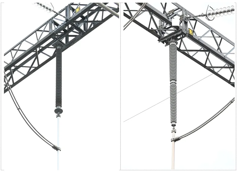
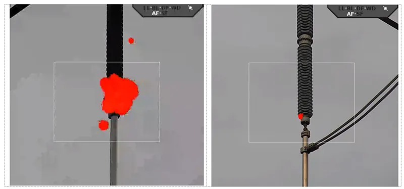
When connecting transmission lines enters the substation the jumper loop from the dead-end tension string connects to the tubes leading down to substation. The connection point has been found to vary between 0.2 and 2 m on the tube and will affect the electric field strength significantly on the insulator. Two examples of different positioning are shown in Fig. 14. The left case where the connection is approximately 1.5 m downwards will result in significantly higher electric field strength on the end fitting in comparison to the right case. This is illustrated in Fig. 15 by UV-images from the two cases. This type of “error” in installation should be avoided and highlights the importance of having guidelines in how to install electrical connections.
Thus, is it important to find the most severe case when performing electrical type tests, such as RIV test and corona test.

Discussion
From all the findings during FAT’s and quality control at site it is easy to understand the importance of attending these. However, many of the findings are of superficial character and may not be fully relevant, and some other findings, which are ok according to the standard, are more concerning. If breaking them down slightly, the sand inclusions and glaze repair on sheds are no concern for the long-term performance of the insulator.
The insulator may still be fit for purpose even if some visual defects are present. However, this gives a hint in the overall quality of the manufacturer. However, the cracks and chips on the insulator body which have been found should never reach an end customer and it is concerning that some manufacturers ships insulators with such flaws to site (really meaning that they skip the visual routine inspection).
If looking at the defects on the end fittings it is surprising that they exist since these parts are provided by a sub-supplier. These defects should be found during quality control from the providing company or at the quality control for arriving goods at the insulator manufacturer. Many of these findings are superficial as well, but it provides hints of the overall quality of the product. Many of the flaws found on the end fittings could still be ok to install in service, but the insulator manufacturer needs to be transparent and report the different types of defects that are present so that the end customer can take a decision.
Most concerning is the spread in mechanical bending failure test. The insulator that failed, did so 20% below the SCL. There was a void present at the edge of the core of the fracture. On the same time the two retests exceeded the criteria with more than 20% resulting in a huge spread of the mechanical performance of the batch. To verify the spread within a whole batch would be costly, but the large spread in mechanical integrity is concerning for the long-term performance and raises questions of how many more there might be of the ‘less’ good examples. There might be a need to increase the number of units for the mechanical failure test to ensure that the spread is not too high.
Svk states a maximum amount of quartz in the insulator body in an amendment to their technical requirements, and this is not always fulfilled. However, it might be more important to consider the quartz particle size rather than the amount of quartz. This has been implemented into an amendment of the Svk technical requirements. A correlation of these and mechanical performance of insulators would be interesting to research in the future.
Regarding composite insulators, these were installed without any quality control at all. The major issue with almost all of these was poor electric field grading. Electric field strength exceeds recommended criteria by a factor of 1.5 and 3.5 in all installed cases without grading ring. The excessive electric field will develop into internal damage with time. The electric field criteria presented in IEC 61109 should be adopted into all other composite insulator standards, such as IEC 62231, to avoid premature ageing.
After service testing has revealed that the adhesion between housing and rod does not fulfil the upcoming requirements in IEC 62217 which indicates that some basic design tests should be performed on sample test level as well to ensure long term performance.
Many of the findings revealed during inspections have been addressed and are continuously worked on by updating routines in quality control at the different steps of design, installation, etc. at Svk. This will require more time and effort from engineers to train contractors, and the tasks of the contractors will increase but it will also provide them with more understanding of the products they are dealing with. This will most likely increase the build time for the first substation, but it will decrease when routines have set in future projects. In addition, the amount of maintenance need in the future will decrease as well. When considering the above, it is important to understand how the insulator will be influenced by nearby equipment and thus defining the ‘worst case’ when performing the electrical type tests of the insulator.
If designing busbars, connections, insulators, etc. to fulfil the ‘corona free’ substation it would be a major step in diagnostics. This is fully possible from technical and practical point of view. Any contractor or maintenance crew will take notice if the hear anything abnormal before going there with more advanced cameras and operators with more training in diagnostics of high voltage equipment.

Conclusions
The manufacturer has a responsibility to check the products before shipping to avoid basic quality issues, which are stated within the routine test that the manufacturer should perform. But this project has highlighted how important it is for the utility to attend the FAT’s and making sure that the quality control at the suppliers is up to the standards.
It is good if the utility has a routine to check incoming material before installation. To be able to do so, a routine with training of the personnel building the substation is vital, making sure that they know what kind of material they are handling and why they should be doing it in a certain way.
If succeeding with creating ‘corona free’ substations, as stated in Svk’s technical specifications, it will be a huge leap forward into diagnostics. All maintenance personnel will be able to hear when discharges have started somewhere.
Finally, the sample and routine tests regarding composite and porcelain station post insulators might need to be updated to fully understand the batch quality of these products.
References
[1] M. Radosavljevic, I. Gutman, C. Ahlholm, P. Sidenvall: “Ageing and deterioration of composite post insulators exposed to high electric field in 220 kV and 400 kV switchyards in Swedish network”, 2017 CIGRE SC B3 Colloquium, Recife, Brazil, 18-20 September 2017.
[2] P. Sidenvall, A. Sandoval, A. Taheri, J. Remelin: ”New competencies and diagnostic methods needed for the application of composite insulators in substations”, Cigre Session Paris, B3-10795, 25-30 August 2024, France.
[3] P. Sidenvall, P. Sahlén, E. Björk, B. Bartholdsson: ”Service inspections and status assessment of composite station post insulators”, INMR 2025 Panama, Panama City, 19-22 October 2025.
[4] IEC Standard: “Tests on indoor and outdoor post insulators of ceramic material or glass for systems with nominal voltages greater than 1 000 V”, IEC 60168 Ed 4.2, 2001.
[5] Svenska kraftnät teknisk riktlinje: “Stamnätsstationer”, Svk TR01-01 utg. 11, 2022.
[6] A.J. Philips, A.J. Maxwell, C.S. Engelbrecht, I. Gutman: “Electric Field Limits for the Design of Grading Rings for Composite Line Insulators”, IEEE Transactions on Power Delivery, Vol. 30, No. 3, June 2015, p.p. 1110-1118.
[7] I. Gutman, P. Sidenvall: “Optimal Dimensioning of Corona/Grading Rings for Composite Insulators: Calculations & Verification by Testing”, INMR World Congress & Exhibition on Insulators, Arresters & Bushings, Munich, Germany, 18-21 October 2015.
[8] P. Sidenvall, et al.: ”Limits of electric field for composite insulators: state-of-the-art and recent investigations of overhead line insulators purchased by power utilities”, CIGRE Science & Engineering, N. 24, February 2022.
[9] P. Sidenvall, F. Lehretz: “Key factors for reliable results in E-field simulations of OHTL insulators”, CIGRE Symposium, paper 10265, September 29 – October 3, Montreal, Canada, 2025.
[10] IEC Standard: “Radio interference test on high-voltage insulators”, IEC 60487 Ed. 3, 2023-12.
[11] IEC Standard: “Overhead lines – Requirements and tests for fittings”, IEC 61284 Ed. 2, 1997.
[12] M. Ruokanen, A. Trník, O. Al-Shantir, D. Mikušová: ”Impact of Residual Quartz on Lifetime of High Strength Porcelains”, INMR World Congress & Exhibition on Insulators, Arresters & Bushings, Berlin, Germany, 16-19 October 2022.
[13] IEC Standard: “Insulators for overhead lines – Composite suspension and tension insulators with AC voltage greater than 1 000 V and DC voltage greater than 1 500 V – Definitions, test methods and acceptance criteria”, IEC 61109 Ed. 3, 2025.
[14] IEC Standard: “Composite station post insulators for substations with a.c. voltages greater than 1 000 V up to 245 kV – Definitions, test methods and acceptance criteria”, IEC 62231 Ed. 1, 2006.
[15] IEC Standard: “Polymeric HV insulators for indoor and outdoor use – General definitions, test methods and acceptance criteria”, IEC 62217 Ed. 3, to be published 2025.