Over half a century after their introduction, there still exists debate on the state-of-the-art of composite insulator technology. The only consensus seems to be that there has been much improvement compared to early generation designs (which also account for most of the unsatisfactory service experience).
So, one might ask: why is there still lack of agreement on whether composite insulators will ever offer a realistic alternative to glass and porcelain insulators? This edited past contribution to INMR by independent T&D expert, Alberto Pigini, offered insight into the answer to this question. He believes that most failures of composite insulators are not intrinsic to the technology but rather due to inappropriate selection and specification.


The underlying issue behind contradictory views on the reliability of composite insulator technology lies in the fact that performance of any insulator depends largely on choice of design given its intended service environment. Unfortunately, in the case of composite insulators, this has not always been done correctly. For example, whereas inappropriate or too superficial an electrical specification can lead to flashover for ceramic insulators, this can result in permanent damage in the case of composite insulators.
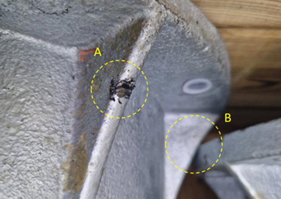
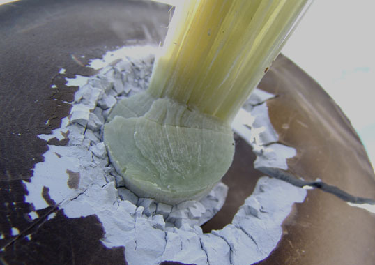
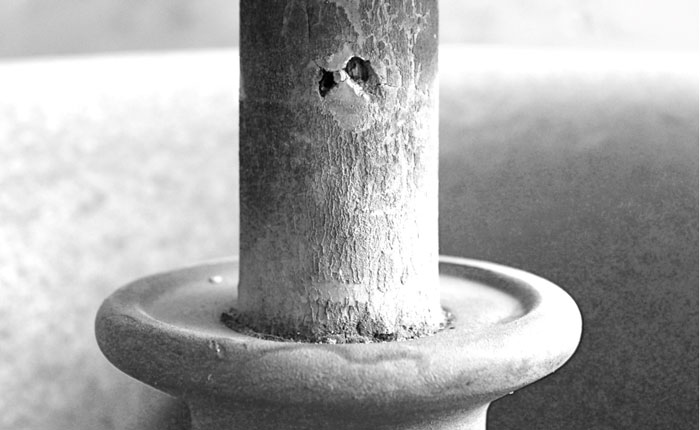
Composite insulators offer well-recognized advantages. However, contrary to what was originally promoted, they are not ‘indestructible’. Therefore, to ensure performance comparable to or better than that expected of ceramic insulators, care must be taken in their specification, handling and installation. In fact, failure analysis of reported problems with these insulators has shown that most were due to deficiencies in specification and selection from the electrical point of view. Electrical design of composite insulators should not be made looking solely at flashover performance during short-term tests but must instead be based on risk of surface degradation from partial discharges that over the long-term can cause tracking, erosion and eventual failure.
This is a critical shortcoming since composite insulators are especially vulnerable to damage should there be continuous partial discharges and arcing activity on or near their surfaces.
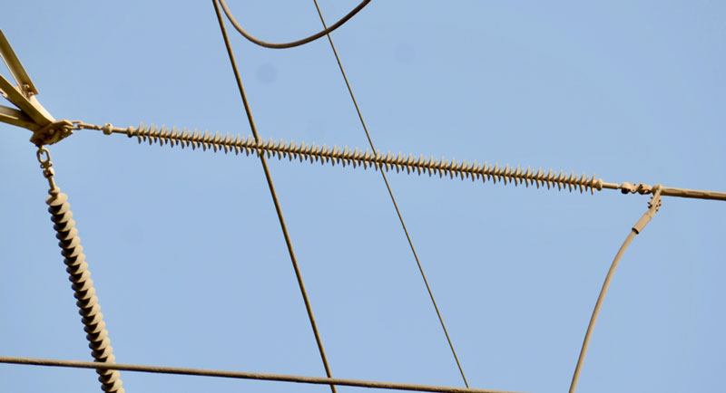
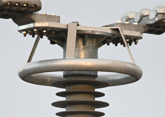
installed without field grading rings.
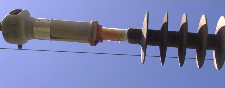
For example, some documented failures have been due to insulators being installed without suitable shielding electrodes to limit electric field gradients near their high voltage end (and even at their earth end in the case of high system voltages). Similarly, many failures have also been the result of inaccurate estimation of the actual pollution service environment.
CIGRE Brochure 142 explained that experience from laboratory ageing tests as well as field trials confirmed that there are three classes of leakage current on composite insulators under normal wetting conditions:
a. a low-value, highly intermittent class;
b. a relatively high average current of a few mA, but far from values typical of pre-flashover conditions;
c. a high current value class (i.e. some hundreds of mA) indicating that the insulator is nearing flashover.
While ceramic insulators are designed looking mainly at the ‘c type’ class of leakage current, composite units should be designed instead taking ‘b type’ currents into account. In fact, past research indicated that while class ‘a’ currents have little influence on long-term performance, class ‘b’ currents can lead to tracking and erosion and possibly permanent failure.
As a result, there should always be sufficient design margin between withstand severity and actual environmental pollution whenever selecting composite insulators. The critical need is to limit leakage current over the full service life taking into account the possible influence of service stresses on surface hydrophobicity and wettability.
In the case of composite insulators (either AC or DC), the conventional approach based on the pollution classes defined in IEC 60815 is therefore not recommended. Rather, to assure satisfactory service performance, a statistical approach must be made that accounts for both environmental parameters and specific insulator characteristics.
In particular, specification in terms of required creepage distance alone is not sufficient. For example, the efficiency of a profile may become low if too much creepage is forced on a given arcing distance. Indications as per IEC 60815 should ideally be regarded more an ‘orientation tool’ but not a substitute for the information that comes from testing. For those composite insulators already installed on lines and where it is too late to change specifications, diagnostics based on measuring leakage current along selected units can help identify any insufficiency in design and trigger remedial action, e.g. washing, should average leakage current values reach the destructive class ‘b’ type.
While only electrical design is considered above, suitable specification from the mechanical point of view is of course also important and possibly even more so than for ceramic insulators. Again, many reported failures, especially on recent generations of composite insulators, have been due to inaccurate mechanical specification or by practices that do not take into account that permanent damage can occur due to mishandling or poor installation methods.
In principle, the maturity and intrinsic reliability of composite insulators can be considered satisfactory and of the same high level as ceramic insulators. However, reliability in practice will depend on whether the electrical and mechanical specifications are accurate and also account for their special characteristics, response to specific service stresses and methods of installation.