Many factors have to be considered when attempting to optimize choice and sizing of insulators for substation applications. These include mechanical, electrical, environmental, functional and economic considerations.
This edited past contribution to INMR by Marco Nosilati and Davide Momesso of GE Grid Solutions in Italy, in co-operation with independent expert, Alberto Pigini, analyzed different technical parameters for optimized selection of post insulators, with focus on EHV and UHV disconnectors.
An insulator is defined as: “a device intended for electrical insulation and mechanical fixing of equipment or conductors which are subject to electric potential differences”. This is a highly generalized definition inasmuch as there are many types of post insulators used at substations and converter stations, depending on application, e.g. bus supports smoothing reactor supports, switchgear, busbars, etc. A disconnector is “a mechanical switching device which provides, in the open position, an isolating distance in accordance with specified requirements”. The requirements to be respected for disconnector devices in open-air applications are many but can be divided into three main classes:
• Functional & Electrical Requirements
The main function of disconnector is to guarantee safety. In the open condition, it therefore has to grant a visible and reliable open gap; in a closed condition, it must withstand normal and fault current without interruption or abnormal unsafe situations. A disconnector also has to be designed to avoid discharges across the open-air gap and to earth.
• Mechanical Requirements
From the mechanical point of view, in addition to its own operating loads (weight, operational requirements), the disconnector also has to bear external loads. On UHV equipment, the most severe of these is earthquake. A highly precise design must therefore be achieved if there are seismic requirements. Other loads to also be considered are short-circuit, high wind and terminal loads.
• Environmental Requirements
Being exposed to open air, disconnectors have to withstand all possible environmental factors, including severe ice (important since this can completely change performance of insulators) and heavy rain (which enhances discharge risk). Above all is impact of pollution, which is a key dimensioning factor for insulators and can lead to discharge to earth.
Since all these requirements link closely to insulator performance, post insulators are one of the most important components of a disconnector. At the same time, additional requirements link to displacement under load in service, meaning that disconnectors have one more critical issue to deal with compared to other equipment, namely movement of the mechanical parts necessary for opening and closing. As such, a certain level of rigidity is necessary for proper function of this equipment.
There is a general goal in the electricity supply industry of achieving compact, cost-effective open-air substations. Station post insulator technology can contribute to this goal by limiting necessary arcing distances for busbars, disconnectors and other apparatus. This can be achieved by optimizing post insulator design through selecting the most suitable materials, improving mechanical strength and stiffness, reducing number of stacks and intermediate flanges as well as optimizing shed profile and creepage factor. In regard to UHV applications, the main challenge for post insulators relates to height, particularly since the pollution environment often requires long creepage distances. Mechanical requirements from bending and torsion loads only serve to make this challenge more complex and can also significantly increase the difficulty of manufacturing such units.
Comparison of Alternative Solutions
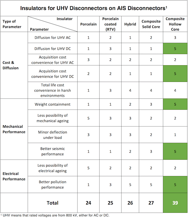
There are basically 5 different options when it comes to post insulators: porcelain post insulators; porcelain post insulators with an RTV coating applied at the supplier’s factory; hybrid units consisting of a porcelain core onto which silicone rubber sheds are mounted; solid core composite post insulators; and gas-filled hollow core composite insulators. Every type has its relative advantages and disadvantages and, as such, it is informative to provide a qualitative comparison of the different designs. Unfortunately, accurate quantitative data cannot be provided in each case since there are many influencing factors – from technical performance to economic considerations that depend on manufacturer, relative cost, country of application, etc. In order to perform qualitative comparison, ratings have been assigned to factors that influence choice of insulator and the resulting Tables obtained for both EHV and UHV classes shows that choice among the different insulator options depends on disconnector voltage rating. In each Table, a score from ‘1’ to ‘5’ has been assigned, where ‘1’ means that the characteristic is poor while ‘5’ means it is a point of strength and highlighted in green.
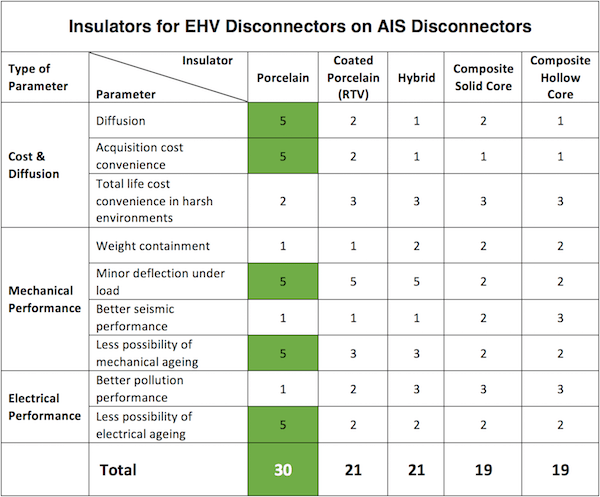
From Tables 1 & 2, and also based on GE experience, it can be said that solid core porcelain is still the preferred and most common choice for post insulators for EHV disconnectors, given the major economic benefit as well as technical reliability of this solution. Most porcelain station post insulators are still based on traditional and relatively low cost stacking technology, whereby insulators of 1 to 2 m arcing distance are stacked in an assembly to reach the desired arcing distance across the EHV to UHV range. However, more advanced porcelain solutions are now also available that allow single unit insulators of several meters to be produced along with optimized profiles that see reduced shed thickness and tip radius. A main issue in this regard is that wide core dimensions are not easy to produce and require special technical skill. For example, manufacture of insulators with wider diameters can result in differential cooling after the molding process, causing cracks. In addition, other parameters such as quality of the porcelain body and cement also have to be considered.
The composite solution permits insulators of whatever length is necessary without flanges while also offering well-known advantages such as low weight and good performance under pollution and seismic conditions. The main disadvantage is higher cost compared to the standard solid core porcelain solution. This limits application at lower transmission voltages. By contrast, hollow core composite insulators, especially those filled with an eco-friendly gas that is properly monitored, seem to be the preferred solution for UHV disconnectors due mainly to the possibility of increased diameter without significant impact on either weight or cost-effectiveness. Of course, such a solution still has to be properly designed to comply with specific mechanical constraints (e.g. minimizing deflection at the top for disconnector applications) and also rigorously tested from the sealing and monitoring points of view. Nonetheless, it must be noted that there is still relatively limited service experience for composite hollow core insulators at UHV.
Porcelain post insulators with an RTV coating applied at the factory of the supplier could represent a good solution for UHV due to excellent pollution performance but comes with the disadvantage of periodic maintenance of the coating, usually guaranteed only for about 10 years. The hybrid solution with porcelain core and silicone shed housing shares advantages and disadvantages of the above solutions. One of its drawbacks is much higher cost with respect to traditional porcelain stacking technology while not offering a significant benefit in terms of weight reduction (i.e. only about 20%). Indeed, cost is a key driver in choice of insulator when it comes to disconnectors given that these account for a significant percentage of overall cost, i.e. up to 30% for EHV and up to 70% for UHV disconnectors. Of course, insulator cost can vary widely depending on supplier location, manufacturing process and technology used.

Mechanical Sizing: Optimization & Constraints
Many aspects have to be considered during mechanical sizing of disconnectors. In regard to the insulators, the key parameters to be taken into account are rigidity, which influences displacement due to load, and resistance, i.e. capability to withstand a load without break. First of all, a disconnector has to ensure electrical continuity, even during seismic events or short-circuits. It also has to operate properly under rated static terminal loads that represent the impact of high-voltage conductors or busbars linked to the disconnector, as recommended by specifications or in the standards. Considering the same diameter, porcelain insulators are more rigid than composite types, with a higher material Young’s modulus by up to 60%. The latter can be subject to high displacement and therefore an accurate design has to be realized whenever composite insulators are selected. It should be noted at the same time that composite insulator technology these days allows these to be offered with very large diameters and this helps compensate partially for the inherent difference in rigidity versus porcelain.
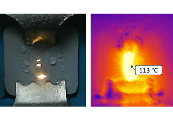
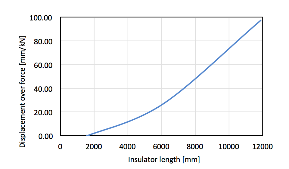
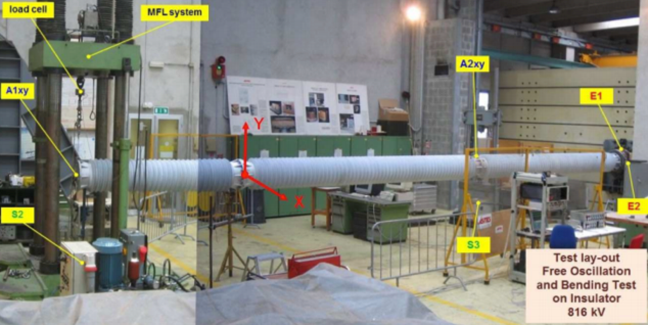
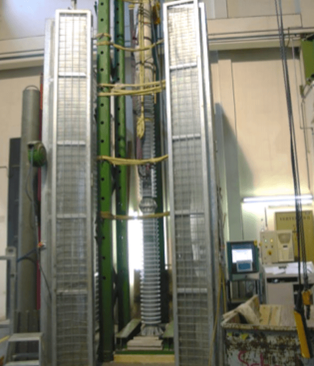
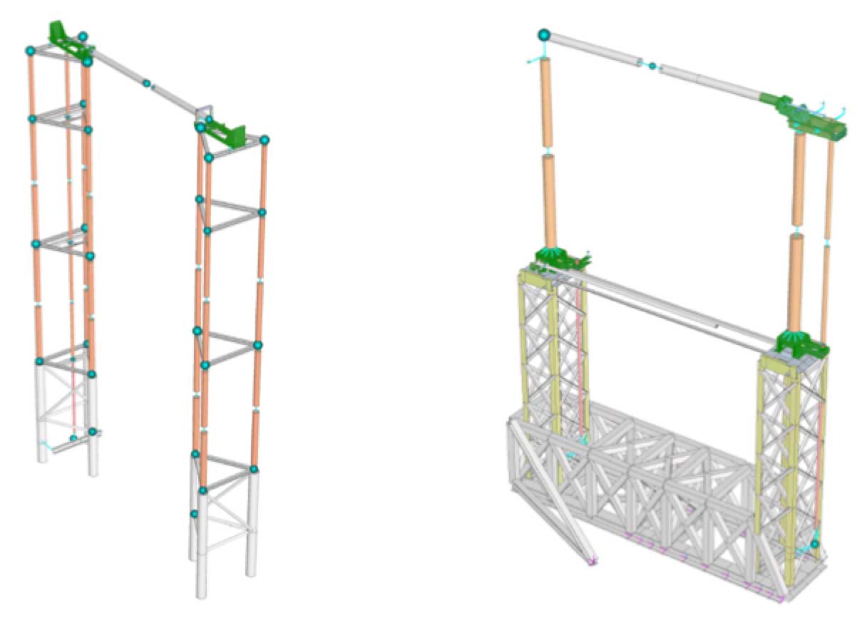
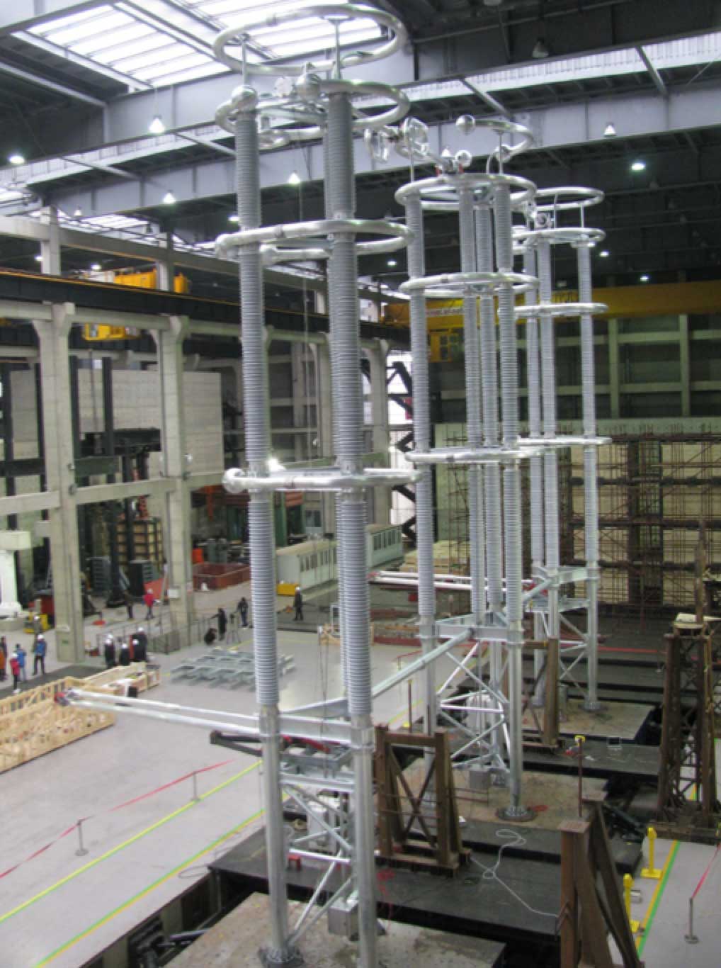
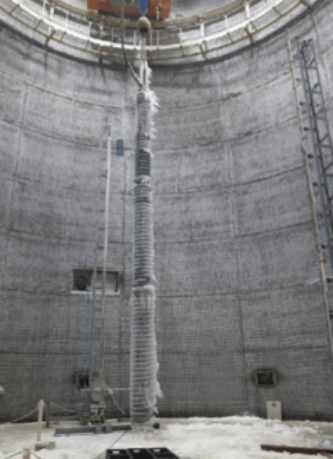
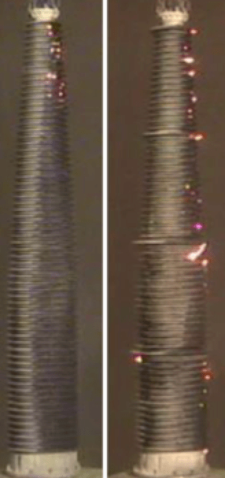
Measurement of displacement under load is an important test, even if it is classified a ‘special test’ and rigidity gains even more importance for UHV projects where insulators are longer than at EHV (see Fig. 1). For example, GE usually performs a bending test along with measurement of displacement under load for its UHV projects. Figs. 2 and 3 show mechanical tests on a hollow core composite insulator and on porcelain.
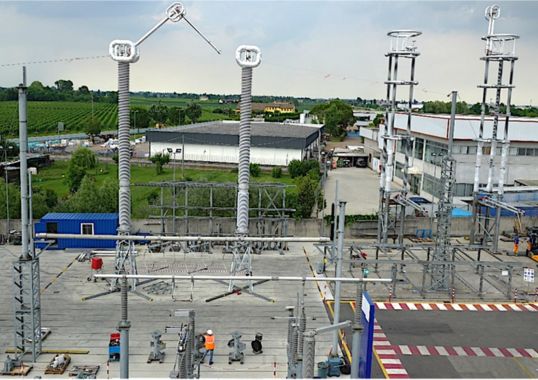
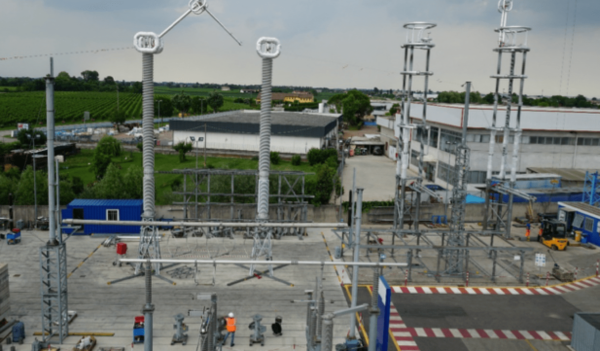
For UHV projects, with high rated static terminal loads or where there are high seismic requirements, GE has adopted two main solutions: more insulators in parallel, as shown in Fig. 4 at right or only a single composite hollow core insulator, as shown in Fig. 4 at left. Since composite hollow core insulators do not have any technical issues, wide diameters can be obtained along with high rigidity.
In regard to the issue of resistance, the most severe mechanical load is usually due to earthquake. Worldwide, there are many seismic standards and technical specifications for disconnectors but the most common are IEEE 693, IEC 62271-300 and ETG-1.020. Unfortunately, these have different qualification procedures and cannot easily be compared. For design purposes, they provide different Required Response Spectra and load combinations. For example, considering X as the longitudinal axis, Y as the transverse axis and Z as the vertical axis:
• IEC 62271-300 requires combining seismic load, the 70% rated static terminal load, the internal pressure of the insulator (if any) and 10 m/s speed wind. Then, it requires to separately combine the loads in the X – Z and Y – Z planes (with the SRSS method) in order to determine maximum stress. The minimum safety factor the insulators must have is at least 1;
• IEEE 693 considers seismic load only, 100% in X and Y directions and 80% in direction Z. The combination (with the SRSS method) has to provide a minimum safety factor equal to 2;
• ETG-1.020 requires combining seismic, rated static terminal load, short-circuit, wind and short-circuit loads, with minimum safety factor of 2.
In seismic design, the goal is to obtain light but rigid disconnectors for the following reasons:
• the lower the mass, the less the seismic load;
• equipment with high rigidity and low mass has high natural frequencies. This way, more vibrational modes could be excited at low loads – outside the maximum peak of the required response spectrum (RRS).
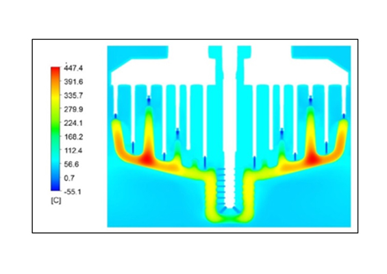
Conversely to these design aims, GE has found in its numerical modeling that an insulator with less rigidity is also subjected to lower stress (see Fig. 5). Indeed, more energy is dispersed due to displacement, thereby enhancing overall damping. As such, wherever possible, real measurements from deflection under load test are used to properly characterize the dynamic behavior of equipment with the aim of trying to balance these two factors: enhance overall rigidity of equipment so as to have vibrational modes outside the maximum peak of the RRS. But if this is not possible, another approach could be to use fewer rigid insulators, which are usually the most critical points.
Given this dynamic analysis, GE considers shake-table tests to be important, especially if high seismic levels are required or for UHV projects. Testing is the only way to evaluate the real seismic performance of a piece of equipment under certain conditions. In FEM analysis, by contrast, it is difficult to properly model all components and some therefore have to be simplified. An example of this philosophy in practice was the shake-table test conducted at 0.4g on SPOL ±800 kV for the Dianxibei Project (see Fig. 6).
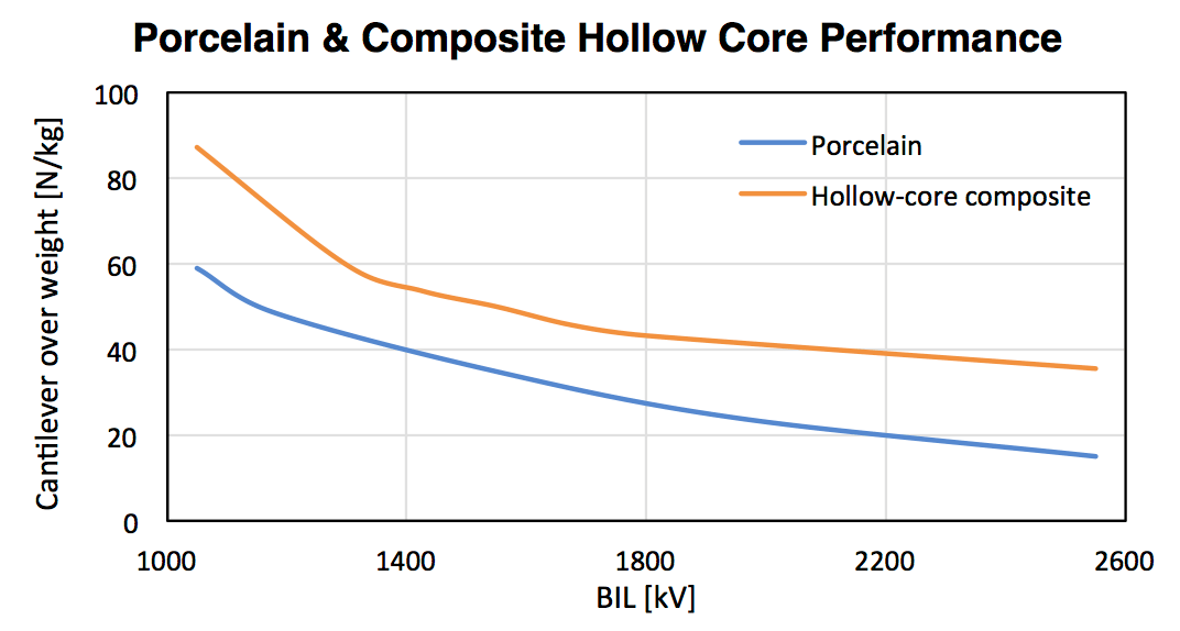
Low weight is fundamental to every disconnector subject to seismic events and becomes even more important for UHV equipment where many meters of length and wide bottom diameters are necessary. Composite insulators are much lighter than porcelain and therefore provide the best dynamic behavior. Fig. 7 provides ratios between cantilever and weight [N/kg] at different BIL values for both composite hollow core and porcelain insulators and shows that composite hollow core insulators provide better performance (i.e. they can withstand higher load for every kg).
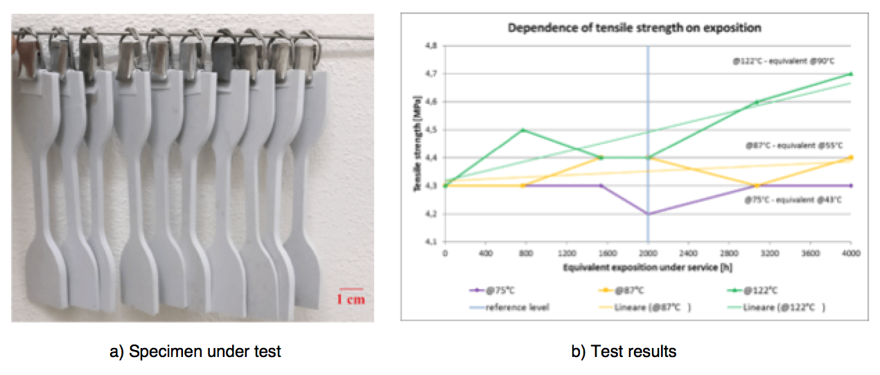
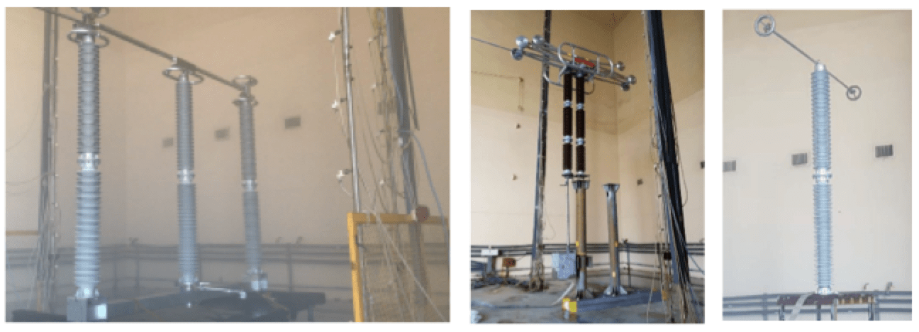
As stated, composite hollow core insulators are usually used for UHV applications. At lower voltages, porcelain often provides acceptable seismic performance while also being less costly. During the mechanical design and validation process, testing is regarded as an especially important aspect when it comes to the above seismic tests as well as in-depth verification of insulator performance (see Figs. 2 & 3). Such tests are performed according to IEC 60168 and also follow a dedicated procedure prepared by GE that is even more severe both for porcelain and composite insulator types in order to ensure the highest possible quality. For porcelain, for example, all type tests from IEC 60168 are performed along with some testing to breakage so as to establish the real resistance. In regard to composite insulators, GE conducts a validation test campaign, especially for UHV, which involves thermal cycle testing (i.e. at different temperatures) and mechanical bending cycles with the goal of simulating a fast ageing test of the material (see Figs. 8a & b).
Indeed, it has been found that temperature can greatly influence properties of composite hollow core insulators but does not considerably impact porcelain. Hot environments can:
• Accelerate material ageing
• Composite materials are normally subject to this phenomenon, accelerated by high temperature, that causes increased loss in insulator performance over time;
• Decrease mechanical properties
• High temperatures cause a decrease in rigidity, especially resistance of the insulator
The fast ageing test on specimens is useful to determine what maximum mechanical load can be applied to a composite insulator given a certain ambient temperature.

Electrical Sizing: Optimization & Constraints
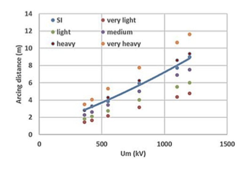
Dimensioning of insulation on EHV and UHV AC disconnectors towards ground and the longitudinal gap is generally dominated by switching overvoltage. This is simulated in a test laboratory by standard switching impulses (250/2500µS). In particular, dimensioning of insulation towards ground is also dominated by switching overvoltages, e.g. under rain conditions, up to conditions of high pollution using insulators with a relatively limited creepage factor (see Fig. 9). SI continues to dominate a project even under more severe pollution conditions using insulators with a larger creepage factor, as foreseen in IEC Technical Specification 60815, or, if necessary, using composite insulators.
Optimal design of post insulators from the contamination point of view has been established based on systematic pollution tests, also taking into account comparative performance at different altitudes (see different test set-ups in Fig. 10). High altitude tests have indicated USCD values higher than those obtained at sea level and confirmed the need to correct RUSCD for altitude. For example, at an altitude of 3500 m withstand salinity is estimated at only about one third that at sea level. Use of composite insulators may therefore be necessary in very heavy and extreme pollution environments or for other reasons, such as to meet seismic requirements.
Systematic SI tests were conducted in GE’s test laboratory as well as at major laboratories worldwide to investigate the SI performance of disconnectors of different types and namely:
• horizontal disconnectors, with a single gap;
• horizontal disconnectors with intermediate electrode;
• vertical disconnectors.
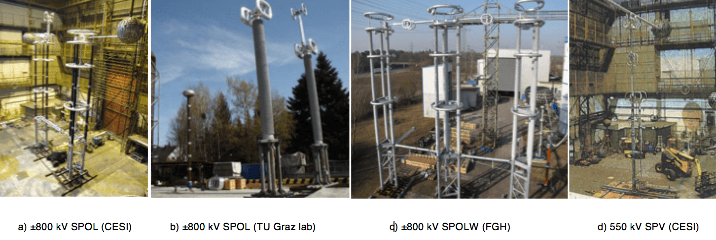
Fig. 11 shows examples of disconnectors under test.
Optimization of SI insulator design was made referring to experimental results and calculations as well as by taking into account available experience on air gap performance developed within CIGRE and, in particular, experience with combined SI and AC voltages (bias tests as foreseen for AC disconnectors) The main conclusion of these investigations was that, given stress values in IEC 62271-1, the distance required between open contacts is generally lower than that required to ground. A conservative design is therefore realized by assuming the same clearance to ground as between open contacts (longitudinal insulation).
DC Applications
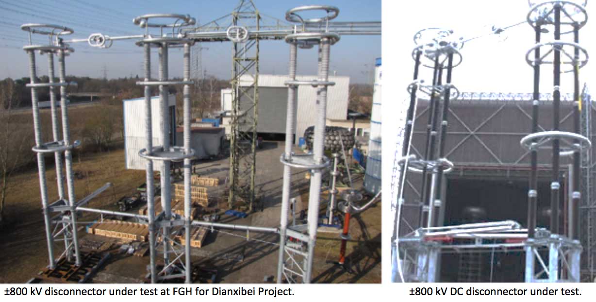
Since influence of DC on SI strength is negligible, design can be made as for AC by applying SI only. Fig. 12 shows examples of configurations under SI testing. Due to required insulation to ground, multi-column insulators may be necessary for the highest system voltages, as in the UHV range.
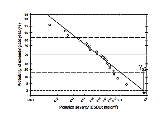
Also, insulation between terminals is verified by applying SI to only one of the terminals. This is because, unlike in AC, no conditions in service can lead to high DC voltage stress in the second terminal. For DC, distance between terminals can be significantly lower than the distance to ground (generally dominated by pollution). By way of preliminary analysis, Fig. 13 offers a qualitative evaluation and comparison of the phase-to-ground pollution requirements and SI requirements (under rain). For qualitative comparison purposes, USCDs were associated to pollution classes, as for AC, taking into account the design curves in IEC 60815 (see Table 3). Maximum applicable creepage factor (i.e. ratio between creepage distance and arcing distance) is assumed to be 4 for ceramic insulators and 4.5 for composite types, in agreement with this Technical Specification.
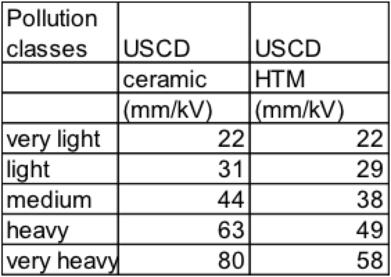
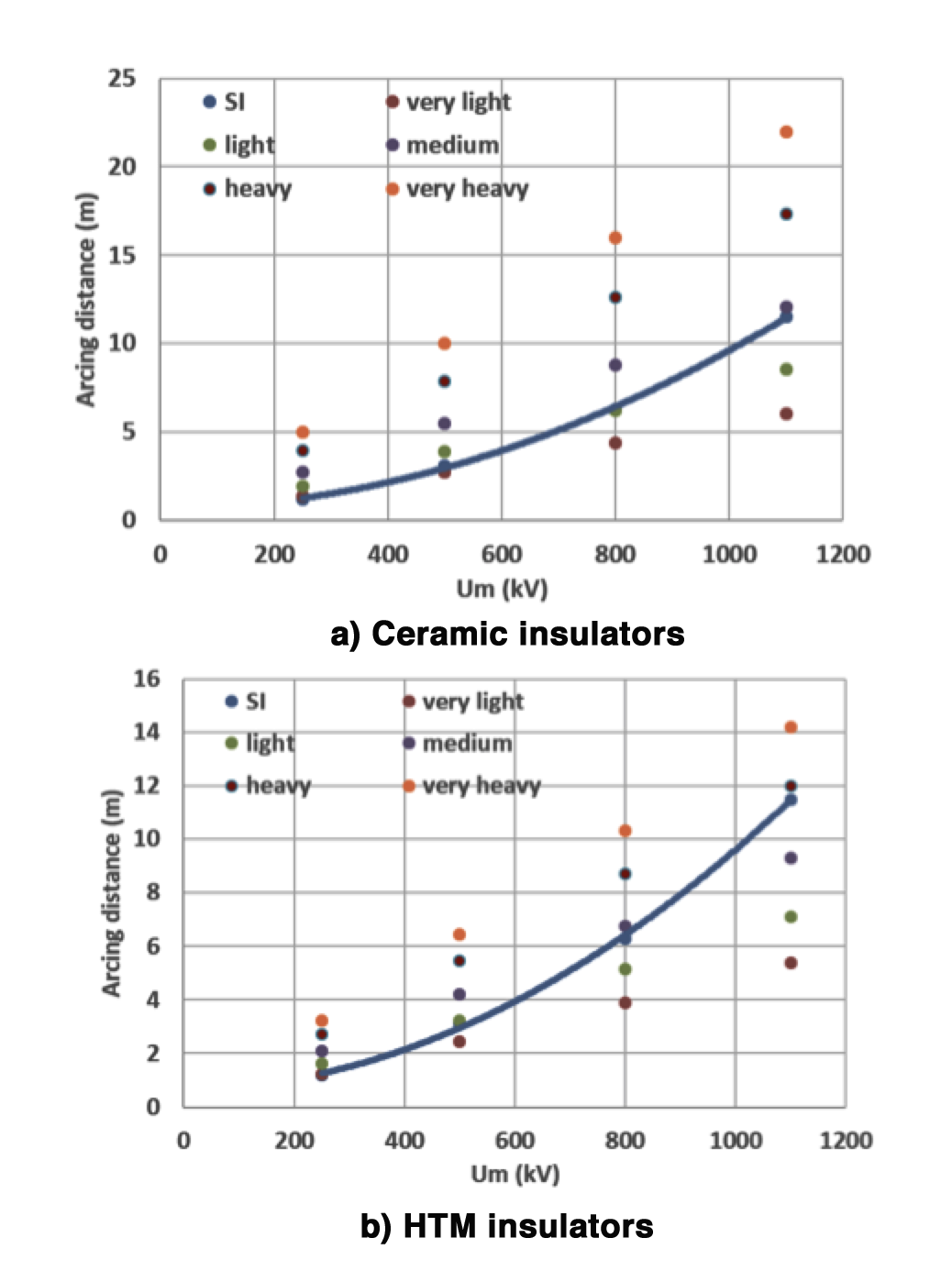
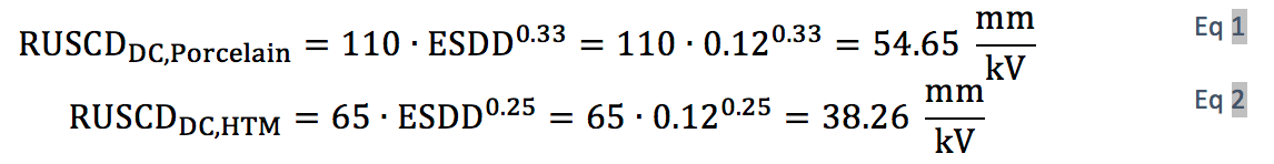
Fig. 13 confirms that, in the case of porcelain, pollution generally dominates phase-to-ground design under most pollution conditions, even when considering high insulator creepage factors. Very long insulator sets may therefore be necessary with porcelain insulators, making this solution impractical or in some situations even impossible, i.e. heavy pollution and high system voltage. More reasonable heights would be required in the case of hydrophobicity transfer material (HTM) insulators such as RTV coated porcelain, hybrid insulators or composite types, the latter being the preferred choice if there are also strict seismic requirements. Indeed, use of HTM insulators can reduce creepage distance by up to 30% (see Eqs. 1 and 2, which consider an ESDD of 0.12 mg/cm2).
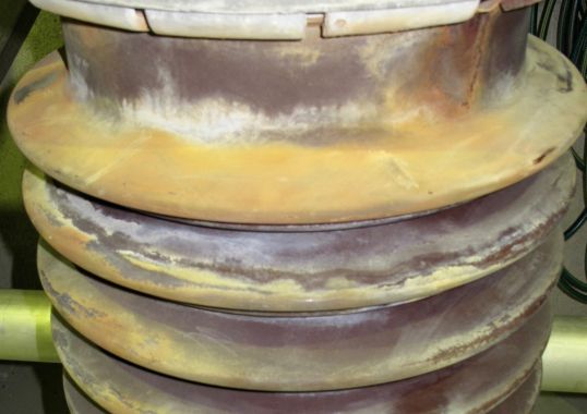
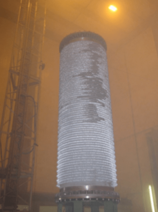
As mentioned, the above gives only preliminary indications. More precise indications for pollution can be derived by results of ad hoc testing. Indeed, systematic laboratory tests with solid layer and salt fog were carried out to select the optimal composite insulator profile and sizing with special attention to harsh environments (see Figs. 14, 15 & 16).
Extreme Environmental Conditions
Aside from pollution, other environmental conditions also have to be taken into account, including severe icing or heavy rain. In cold climates, for example, insulator performance can be affected under severe ice conditions. The design process followed in one such study, presented during CIGRE general Session in 2018, was conservative and based on limited available data. This research determined that insulation performance depends on three main environmental parameters:
• ice load thickness;
• conductivity of the water that froze into ice;
• presence of pollution on the insulator surface.
Insulation performance also depends on three main geometrical parameters:
• arcing distance;
• external diameter of the insulator;
• insulator inclination.

Once the influence of all these parameters has been established, the dielectric performance of an insulator under heavy ice has a linear relationship to length. As such, preliminary design was performed by calculating parameter ‘E, which is the withstand voltage per unit of insulator length. Numerous dielectric tests were then performed to verify insulation performance (see Fig. 15).
In tropical climates, heavy rain can influence insulating performance. Some of the principal conclusions of past research in this area include:
• Large station insulators, especially in the vertical position, can be critical under heavy rain conditions (according to service experience);
• In general, average rain parameters can be considered adequate given that the highest overvoltage values have only low probability of occurring at the same time as the most severe rain. If extreme environments are concerned (e.g. high rain rate and/or high rain conductivity), further analysis may be necessary;
• Under severe rain conditions, greater distance between sheds is advisable.
Summary & Conclusions
Optimization of post insulators for substation applications from the mechanical and electrical points of view depends on many factors and also on environmental conditions such as pollution, heavy icing and high temperatures.
Considering disconnectors, applications requirements include the capability to maintain electrical continuity (i.e. avoiding separation of main contacts) as well as ensuring proper operation. As such, insulators must have a certain rigidity to avoid high displacements at terminals given that displacement under load is a key-driver in design. If a stand-alone supporting insulator is considered, there is less need for rigidity and a more flexible insulator can be used. This reduces its stress while also enhancing seismic performance, taking into account the values of modal frequencies and of RRS peak limits. Another key element in insulator selection is cost effectiveness.
For EHV, the most common insulator type is porcelain, which is also the least costly. At UHV, however, porcelain is often no longer the most cost-effective solution and, as with HVDC applications requiring very long creepage distance, hollow core composite insulators become competitive with other types. Similarly, composite insulators can be adopted under severe service conditions in terms of pollution and seismic conditions. In fact, creepage distance requirements in such cases would make porcelain insulators too high and weak from the mechanical point of view – especially under seismic loads.
At the same time, it should be noted that composite insulators, both hollow and solid core, could face possible additional issues such as risk of premature ageing of the silicone material or loss of hydrophobicity over the expected service life. Moreover, since hollow core composite insulators need to be filled with gas or foam, GE has developed a patented eco-friendly nitrogen solution for its HVDC AIS disconnectors. A gas leak-detecting device, as already being provided for this equipment, is strongly recommended even if the insulator is sealed so as to best monitor disconnector status over its lifetime and perform predictive maintenance.
Meet and learn from Marco Nosilati and other experts on post insulator selection and application at the 2023 INMR WORLD CONGRESS in Bangkok.
[inline_ad_block]