Introduction
The need for testing at HVDC and UHVDC levels has increased dramatically over the last few years. Typically test objects include valves, cables, line insulators, cable accessories, wall and transformer bushings, optical instrument transformers and station post insulators for different applications. Some of these tests are purely dielectric, however, in many cases they also include pollution testing, which is the main dimensioning factor for outdoor insulation in DC.
Compared to AC there are limitations in the standards as regards to testing using DC-voltage. This is especially valid for pollution testing. For ceramic (porcelain and glass) HVDC insulators the pollution test methods are available in the recent version of IEC 61245. However, for pollution testing under DC of polymeric insulators only CIGRE Guidelines for selection and dimensioning are available at present (Technical Brochure, TB 518) [1]. They include some recommendations for testing of ceramic and polymeric insulators. Many times the customer specifications are referring to old standards that are out of date based on today’s knowledge. For example, pollution testing on a station post composite insulator to be used in a HVDC project is required to be performed based on DC withstand voltage in a contaminated environment according to IEC/TS 61245, Section 3: Salt Fog Method [2]. The lack of standardised test methods forces utilities to specify tests that are not relevant for the application (are not representative for service conditions).
On cable systems the testing is performed in accordance with a technical brochure from CIGRE (TB 496 “Recommendations for testing DC extruded Cable Systems for power transmission at a rated voltage up to 500 kV”). Also in this case there is a lack of standards.
In this paper we highlight some issues that are of importance to consider when performing dielectric, pollution and other climatic testing (e.g. ice and snow) on different type of high voltage equipment with emphasize to DC testing.
DC testing of different equipment
Insulators
General
STRI has unique facilities allowing full scale dielectric and pollution testing of ±800 kV DC line ceramic, glass and composite insulators. The DC generator is capable to supply up to 1250 kV for both indoor laboratory testing and 1050 kV for the outdoor test station. The climate test hall for the tests has a diameter of 18 m and height of 25 m. The temperature can be controlled from -12oC to +55oC. Thus, dielectric, pollution and ice and snow tests can be performed in this hall.
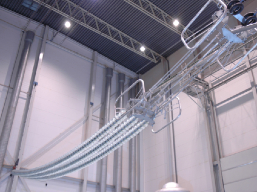
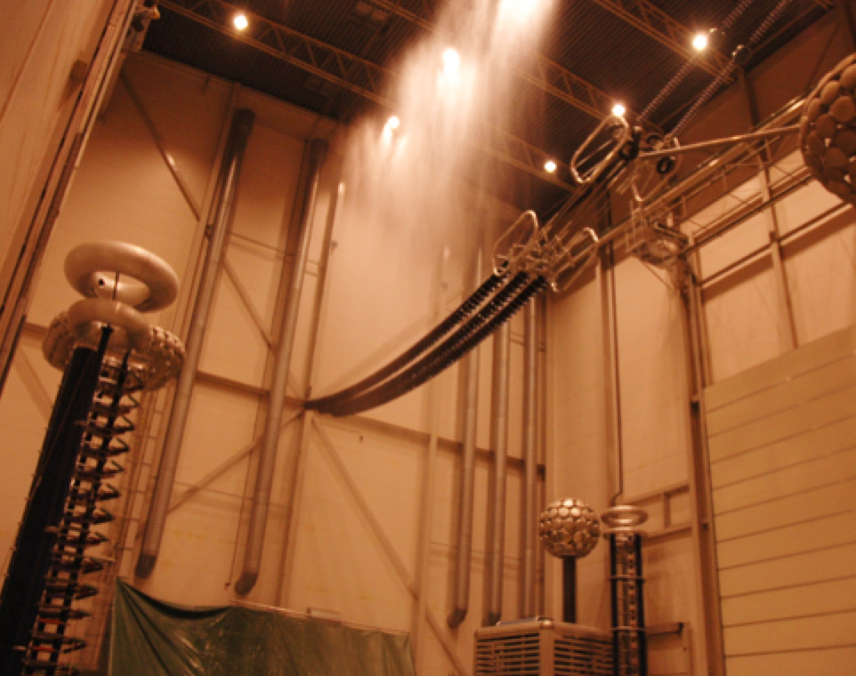
The dielectric testing of the tension strings is done in a horizontal (working) position in high voltage hall (figure 1). However, this puts high requirements on the structure of the building as it is loaded with a high load at the middle of the structure. STRI has solved this by releasing some of the load through an external wire attached to the ground. An alternative way of testing the tension string would be vertical position as was done during the pollution testing. This would simplify the experimental set-up but it would be tougher for the insulation in particularly during rain test as all the rain would accumulate at the bottom of the tension string (as discussed in section 2.1.1 below).
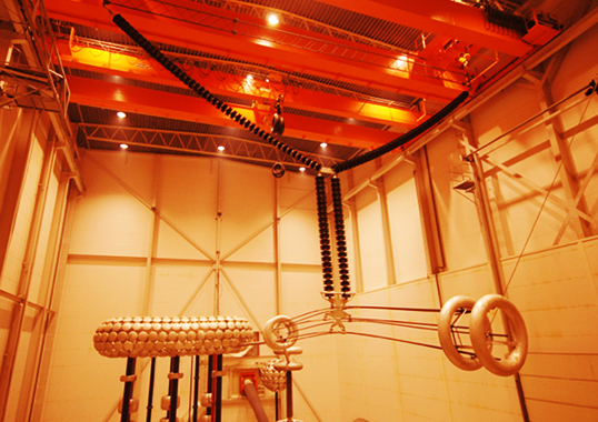
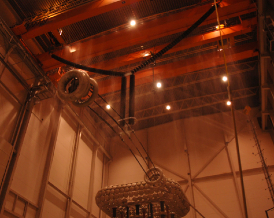
The dielectric testing of Y, I and V-string is done by hanging the insulator string in the crane in the high voltage hall with a lattice structure simulating the closest parts of the transmission tower (figure 2).
STRI has performed a number of DC dielectric tests for different manufacturers of composite, porcelain and glass insulators. Typical testing performed include DC dry and wet withstand test, RIV and dry and wet switching impulse. In our case “wet” means rain test. It is clear from the testing that the standards are not up to date in particularly when it comes to wet withstand testing at UHV DC levels. There are two main issues with wet testing.
First, in order to create a uniform rain on tension insulators STRI has installed nozzles at the roof of the high voltage hall (figure 3). As the standard requires the rain was calibrated without applied voltage. Applying a DC-voltage on the high voltage side of the string will charge the water drops and as a consequence they will be repelled from the electrodes. Thus the calibrated without voltage uniform water distribution is no longer uniform. This effect needs to be considered and taken into account when updating the standards.
Secondly, when testing suspension strings, the rain will be applied by a specially designed rain ramp. This needs to be installed pretty high in order to get the rain uniformly distributed along the insulator and at the same time at a safe distance from the insulator string in order avoid flashover to the rain ramp. This put special demands on the nozzles as they need to deliver the rain a long distance which typically is 10-11 m. In addition to this STRI are using another rain system from the roof, in particular for Y- and V-strings (figure 4). This is necessary in order to fulfil the requirements on both the horizontal and vertical components of the rain. Another complexity to fulfilling the requirements on the vertical and horizontal components is at the bottom of a Y-string where all the rain from the insulators above will be collected. This practical experience needs to be considered in future revision of the standards.
Rain testing of large structures like full-scale DC insulator strings needs to be tested in an indoor environment in order to ensure correct distribution of the vertical and horizontal component of the rain.
Pollution Testing
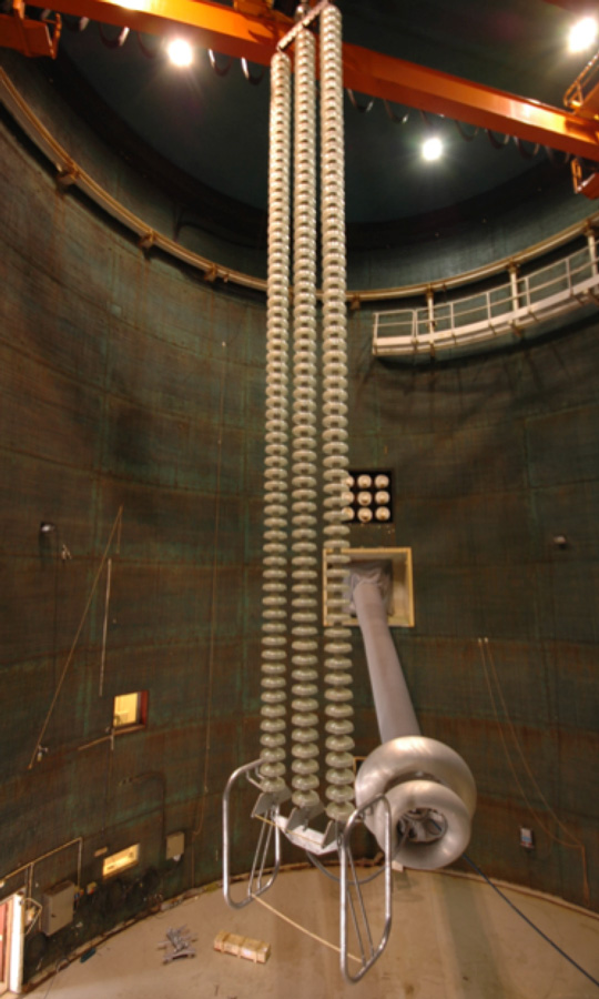
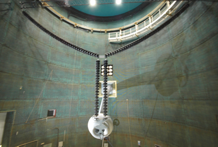
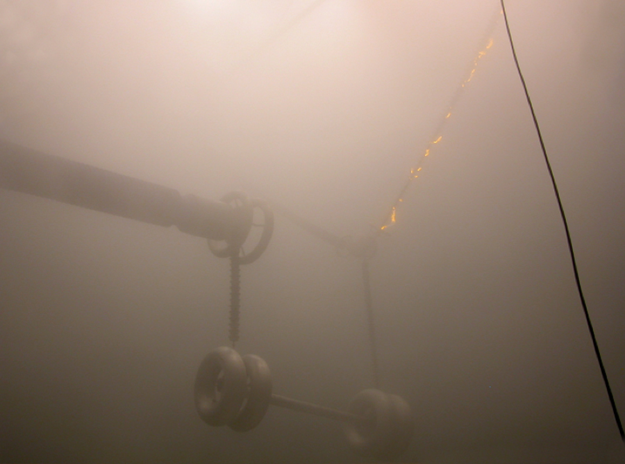
Using the climate hall described earlier STRI has performed full-scale solid layer pollution testing of three possible line insulation options for ±800 kV overhead lines in China and India, i.e. glass and porcelain cap and pin insulators and silicone rubber composite insulators, see figures 5-6-7. The practical complication in such tests was to verify the uniformity of distribution of steam fog in the test during the full-scale tests. Example of pollution testing of a tension string of glass insulators is presented in figure 5. The tension string is tested vertically in contrast to the “natural” horizontal position. This is done due to the fact that it is not practically possible to test 800 kV DC tension strings in horizontal position as they are about 13 m long and with safety distance to the grounded side this means that the hall need to be of the same size as the high voltage laboratory. Testing in a vertical position is tougher for the insulator string to withstand as the condensation of fog on the insulator surface will create runnels along the insulator string. Another example of complications is a need for careful calibration of the uniformity of fog. This was achieved by installation of two small energized insulators at the level of the top and bottom electrodes of 800 kV insulators and 100 min. monitoring of leakage current on them, the results confirmed uniform distribution [3].
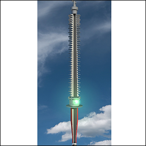
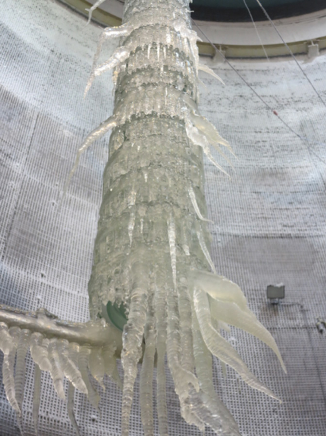
As it was stated earlier, the climate hall makes it possible to simulate ice and snow conditions, it is also possible to make a combination of pollution and ice tests, when the insulators are first contaminated and then accreted by ice produced from water with certain conductivity. For DC this was for so far achieved only for full-scale ±350 kV tests, however feasibility study made by STRI confirmed that it will also be possible for ±800 kV. The unique climate hall provided possibility to produce different types of ice (glaze, rime, snow with different densities and conductivities) according to the requirements from customers, see an example of glazed ice in combination with pollution accreted under full voltage -350 kV (figure 8) [4], [5].
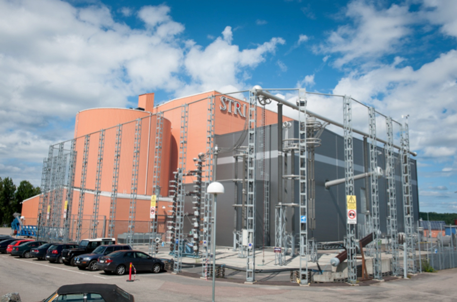
Another issue for polymeric insulators is their long-term performance. To verify this, STRI uses unique field test station outside STRI, see Figure 9. This is where all types of station and apparatus insulation for ±800 kV project were tested and the installed equipment included: wall bushing, optical current transformer, voltage divider, pole arrester, smoothing reactor capacitor, RI capacitor, disconnector and by-pass breaker. The insulators and apparatuses were full-scale tested during more than 2 years at 850 kV and elevated voltages, and later were tested for 2 more years. All components withstood the test with success [6]. Some new insulator options for ±800 kV, e.g. hybrid insulator combining porcelain cylinder and silicone rubber sheds were also verified at this test station recently.
Apparatus Insulators
There are a lot of similarities between apparatus insulators and line insulators regarding dielectric and pollution testing. For rain testing we have the same issues regarding distance between nozzles and test object, ensuring correct distribution of both the vertical and horizontal component of the rain along an insulator that can be up to 11 m long.
For pollution testing we observed that utilities often apply the same requirements on composite insulators as for porcelain insulators. This is due to the lack of standards for pollution testing of composite apparatus insulators. One typical example is requirement for the preconditioning phase for the salt fog test which is directly copied from the standard for porcelain and applied on composite insulators. This phase requires a number of forced flashovers. This phase was historically implemented in the standards for porcelain insulators to assure that the surface will be free from any contaminants before the main test, i.e. that the initial surface conditions should not disturb the main test. However, for composite insulators, such phase may lead to the reduction of hydrophobicity, thus the output could be completely different, i.e. preconditioning may influence the main test. More than that, in some cases to obtain forced flashovers one has to divide the test objects into smaller parts by short-circuiting and test these parts one-by-one, which is rather time consuming.

Accessories for insulators
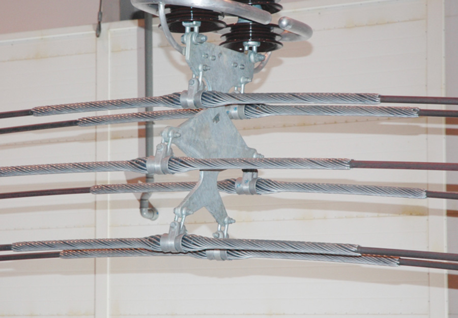
The metallic hardware is often tested at the same time as the insulator string. However, many times the request comes from a hardware manufacturer where they only want to verify their accessories for RIV and corona in accordance with IEC 61284. Practically this means that the test will be performed on a complete string with the hardware attached to it (figure 10). Even though the standard allows for deviations this has to be agreed between supplier and purchaser. It would be suitable to revise the standard to allow for mock-ups of the insulator string and also for performing the RIV/corona test in a vertical as well as horizontal position.
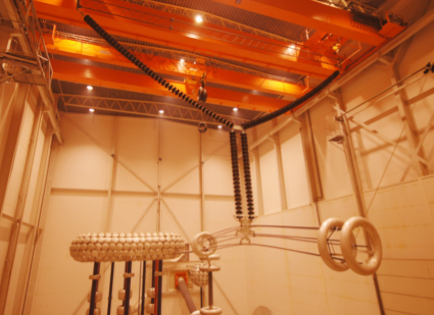
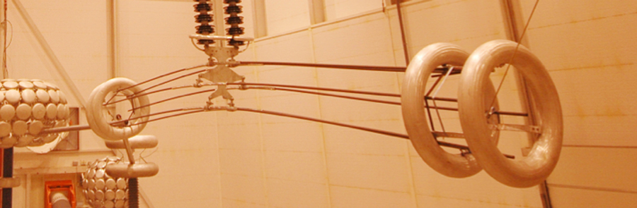
As the demand on DC-voltages and respectively the number of sub-conductors in the bundle are increasing, this has a direct influence on the size of the accessories. The increase in size is not a problem for service however it creates a problem during the testing. The major problem is that the electric field on the surface of the hardware becomes too high due constrains in size of the high voltage halls. Testing of a 6-conductor bundle as in figure 11 already provides a higher electric field on the surface compared to service conditions due to the walls and roof of the high voltage hall.
The standard has two ways of testing and this is by voltage or voltage gradient. As a high voltage hall has limitations in size and thus creates higher electric fields on the surface of the accessories than seen in service the voltage gradient method would give the most correct method. However, in this case there is a need for specifying the voltage gradient which is not given today. This could be added in future revisions of IEC 61284. Modern software programs for E-field calculation provide such verification, however for so far and this was properly verified only for AC [7]. It seems that the similar comprehensive study for DC can be recommended.

Cable systems
Today there are no DC cables for UHV but there are XLPE cables on the market for 525 kV DC. Testing of these cable systems intended for EHV DC-applications is in many cases a delicate task. There are several parameters that can complicate the interpretation of the result. For this reason it is of outmost importance that the testing is done in an accredited lab with experienced personnel and HV equipment that has stable long term performance. All measured parameters should be registered in a computer that allows for post processing and inspection.
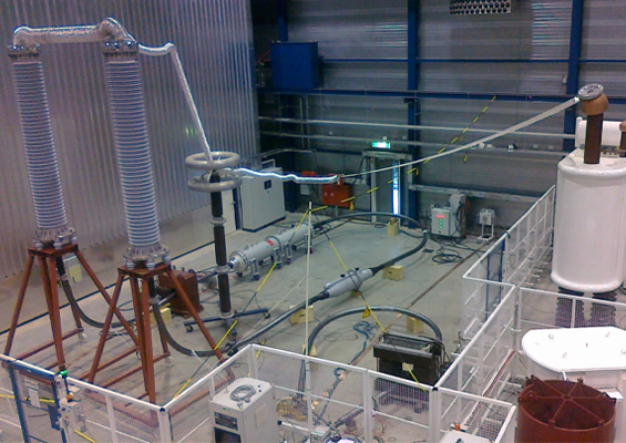
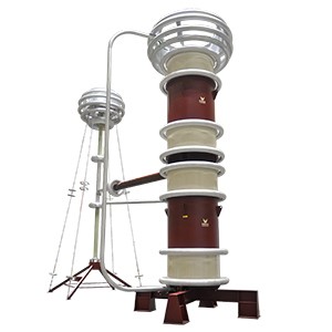
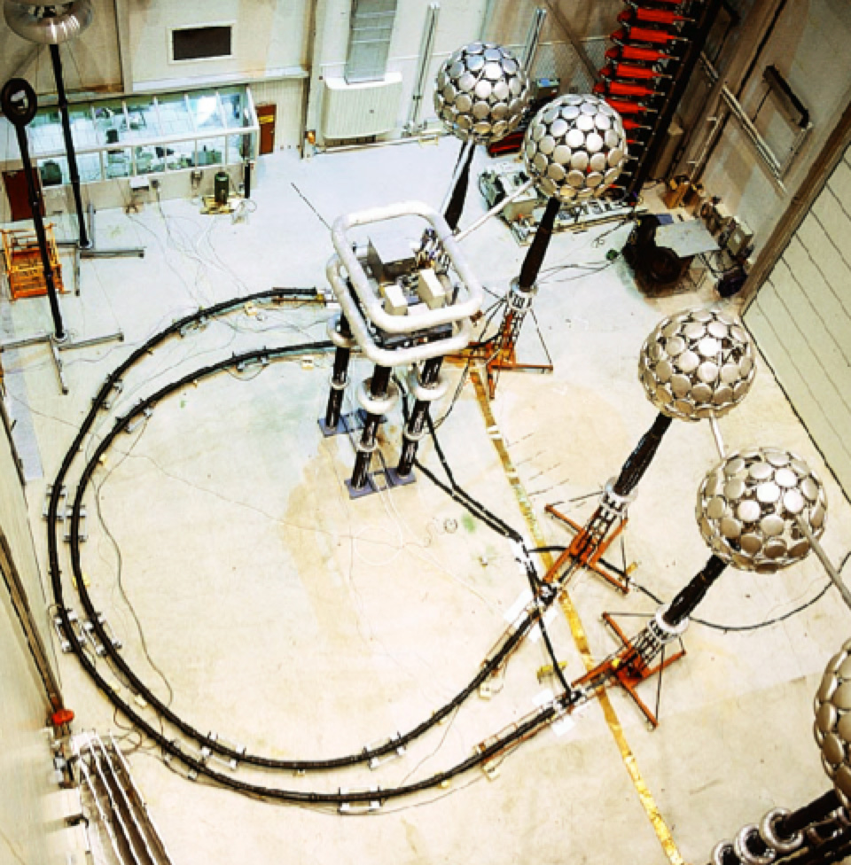
HVDC cable systems are tested in similar way as HVAC systems. There are similarities regarding the load cycling except for polarity reversal but the major deviation comes in the final test where lightning and/or switching impulses should applied superimposed on the DC-voltage. The test circuit for this task needs to be carefully designed in order to avoid flashovers in the test circuit and for protecting the impulse generator for the DC-voltage as well as the DC-generator for the impulse voltage. Performing a type test inside a high voltage hall is a difficult but manageable task (figure 12). However, after performing a 1-year prequalification test on a 100+ m cable the guidelines from CIGRE allows for superimposed impulse testing on a 30 m section of the cable but the requirements from the end user can be that the complete system with all the accessories should be tested. Applying superimposed impulses on DC-voltage with full length cable system puts extremely high requirements on the test circuit and on the individual components such as the DC-generator and the impulse generator.

Summary
This report summarises some of the practical experience that STRI has gathered regarding HVDC dielectric and pollution testing of different types of high voltage equipment. It can be concluded that there is still quite a lot of work needed in order to adapt the different standards to a such a level that testing can be performed in the existing high voltage laboratories even though the system voltage levels are increasing.
References
1. S Engelbrecht, J.P. Reynders, I. Gutman, K. Kondo, C. Lumb, A. Pigini, V. Sklenicka, D. Wu: “Outdoor Insulation in Polluted Conditions: Guidelines for Selection and Dimensioning Part 2: The DC Case”, CIGRE Technical Brochure 518, December 2012
2. IEC Standard 61245: “Artificial pollution tests on high-voltage ceramic and glass insulators to be used on d.c. systems”, Edition 2.0, 2015-03
3. Windmar, I. Gutman, J. Jonsson: “HVDC Pollution Testing of Insulation – Experience from Service, Laboratory and Test Station”, IEEE Transactions on Dielectrics and Electrical Insulation, Vol. 21, No. 6, December 2014, p.p. 2496-2502
4. Dernfalk, J. Lundengård, E. Petersson, I. Gutman, K. Tucker, S. Banerjee: “Advanced test methods for full-scale ice tests of DC insulators strings intended for ±350 kV”, IWAIS-2015, Uppsala, Sweden, June 28 – July 3 2015
5. Tucker, A. Dernfalk, I. Gutman: ”Full-Scale Testing of HVDC Energized Insulators for High Salt/High Ice Environment”, World Congress & Exhibition on Insulators, Arresters & Bushings, Munich, Germany, 18-21 October 2015
6. Kumar, D. Wu and R. Hartings, “Experience from first 800 kV HVDC Test Installation”, International Conference on Power Systems (ICPS-2007), Bangalore, India, 12-14 December 2007.
7. Gutman, P. Sidenvall: “Optimal Dimensioning of Corona/Grading Rings for Composite Insulators: Calculations & Verification by Testing”, World Congress & Exhibition on Insulators, Arresters & Bushings, Munich, Germany, 18-21 October 2015