Newly developed surface engineering techniques as well as more advanced coatings now offer enhanced self-cleaning and improved icephobicity and anti-corrosive properties. These technologies benefit the power industry by reducing risk of insulator flashover and lowering corona losses and noise from conductors and line fittings. Similarly, they help alleviate corrosion as well as mechanical problems caused by ice and snow accretion on overhead networks. They even support environmental issues by reducing visual impact of power lines.
This edited past contribution to INMR by international T&D expert, Alberto Pigini, and Pasquale Graziosi of EKD Project in Italy reviewed coating application in power systems and also illustrated a case history of success achieved with one such application involving RTV coatings.

Coating Application on Conductors
Specialized coatings are used these days to reduce noise, mitigate corrosion and impact of icing. Moreover, when necessary, they can also allow conductors and insulators to better blend with their environment through camouflage.
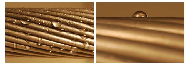
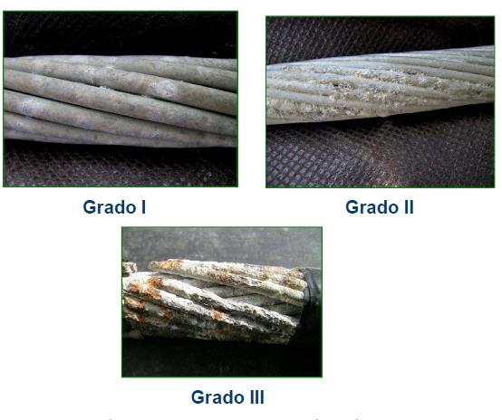
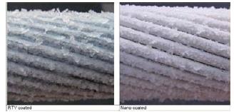
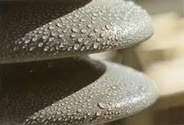
For example, coatings help reduce conductor noise (i.e. radio and audible noise) when it is new, especially in the presence of rain and other conditions leading to water droplets forming on the conductor. Beyond surface treatment, another solution in this case is to reduce hydrophobicity by application of a hydrophilic coating, such as shown in Fig. 3 where a TiO2-based coating is applied with three layers. Another problem, especially in harsh environments, is conductor corrosion. A review of all possible coating technologies to mitigate corrosion has been made, going beyond only metallic coatings including galvanizing or electroplating, inorganics such as phosphate or chromate conversion coatings, anodising or vitreous enamelling are examined. By selecting a suitable colour, the coating can also prevent reflexion and camouflage conductors against their backgrounds. Finally super-hydrophobic coatings can help reduce ice formation during wintry conditions.
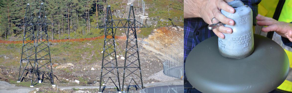
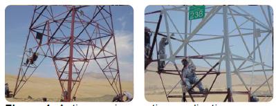
Coatings can also prove highly beneficial to prevent corrosion of towers and line fittings in harsh environments, as shown in Fig. 6. For example, application of an alkyd anti-corrosive coating (see Fig. 6) has been found highly efficient, with less than 9% of structures requiring re-coating after 10 years. As for conductors, by using the right colour, coatings help camouflage not only towers but full lines as well.
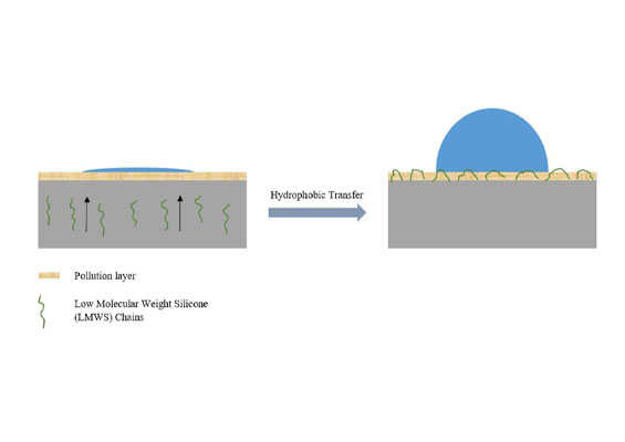
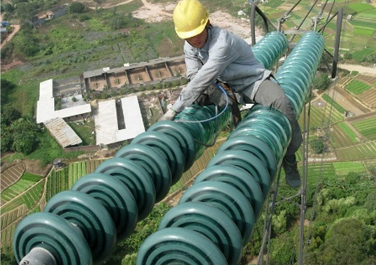
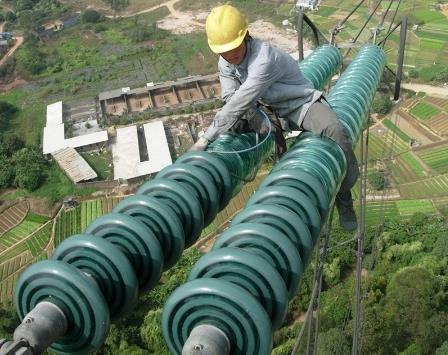
Finally, the main problem in the case of ceramic insulators is to increase pollution performance in harsh service areas. This can be accomplished by applying coatings to render their surface hydrophobic, as in Fig. 8.

Case History with RTV Silicone Coatings
One of the most successful examples of coating application in power systems has involved improving pollution performance of ceramic insulators. Traditionally, RTV silicone material has been regarded mainly as a remedial measure to mitigate pollution-related flashovers of substation insulators in harsh service areas – in place of greasing or washing. However, in situ application of RTV coatings on installed insulators has always been perceived as problematic due to unsafe working conditions as well as the difficulty in always applying a uniform and complete coating.
More recently, there has therefore been growing interest to adopt pre-coated cap & pin string insulators as an option during the design phase of a new line or to replace insulators found inadequate in coping with actual pollution conditions. In such cases, pre-coating insulators in a factory setting became the standard solution to give them a uniform, highly adherent hydrophobic surface before they enter service. Evolution of this trend, which began around 2004, is highlighted using experience gained in Italy on insulators applied to power lines operated by Italian TSO, Terna.
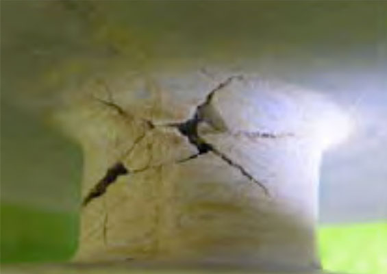
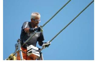
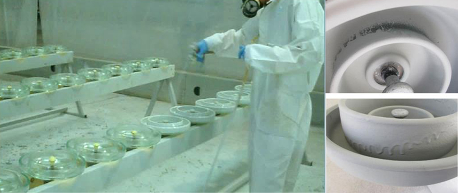
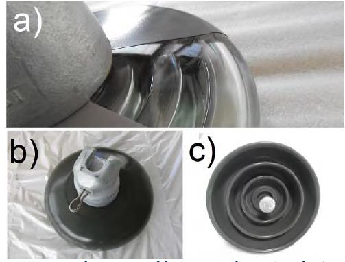
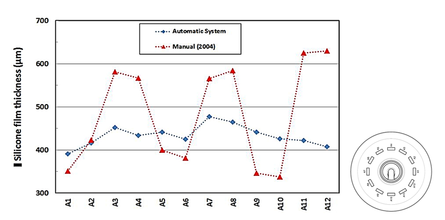
At the time, application of coatings was a manual task, typically done directly on insulators already in service on a line or in a substation. Terna then requested that application of RTV silicone ideally take place on insulators before installation and the resulting first batch of 3000 insulators was coated manually by spraying. One leading coating manufacturer, which had supplied Terna with its coating for evaluation, developed special instructions for manual application of an RTV silicone. That first batch was produced manually by their technician in a confined environment at the facilities of EKD Company in late 2004. However the resulting coated insulators were found not to meet Terna specifications. One of the issues was that quality and productivity were greatly affected by operator skill and many pieces had to be re-worked due to non-compliance with requirement for homogeneous thickness or due to inadequate coverage in difficult-to-reach areas of insulators. Fig. 9 shows these non-compliance issues from manual application. Post application curing was carried out in large area with controlled temperature as well as filtration and ventilation system.
Aside from non-compliance issues, the initial manual method also yielded over 50% material waste, high worker safety costs (e.g. protective equipment and constant shift changes to limit worker exposure time) and environmental costs linked to recovery and disposal of improperly applied coating. Based on this initial experience, automatic application was considered mandatory and development started in this direction.

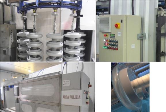
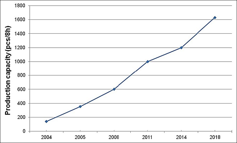
In 2005, Terna requested an additional 30,000 pre-coated insulators and, considering productivity and quality issues from manual application, a semi-automatic system was set up. Application quality and productivity both increased significantly. Subsequently, a succession of further innovations led to further improved performance, especially from the viewpoints of environmental protection and worker safety due to reduced need for operators. Moreover, production using an automatic system allowed superior uniformity of coating thickness, increased productivity and reduced quantity of coating required per insulator compared to initial manual application. Operator presence during automatic coating is limited to loading and unloading, thereby reducing contact between worker and chemicals. The coating process is attended by trained personnel whose role is only to control the process and assure that insulators are clean before application of RTV material and that post-application curing takes place under constant temperature and humidity parameters. Moreover, fully automated spraying allows thinner stratification and has the intrinsic flexibility to modify set-up to obtain the same performance for different types of coating and/or insulator.
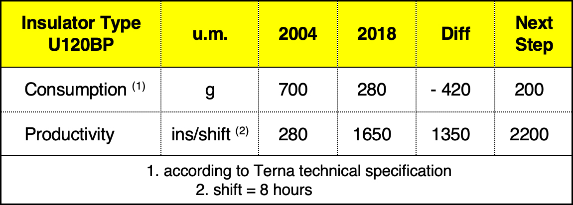

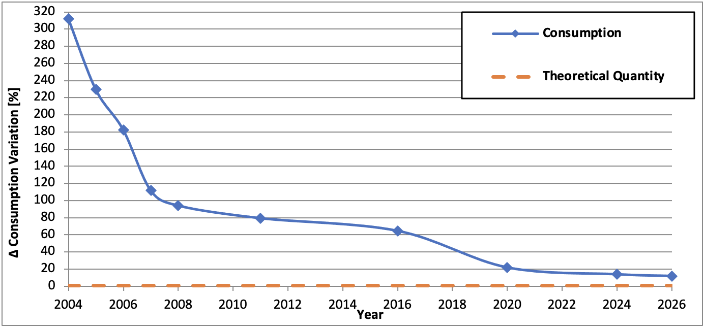
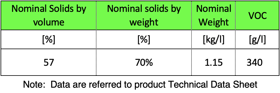
As evident from Fig. 15, silicone coating wastage under the automated system has significantly reduced versus the manual application performed in 2004. Table 2 outlines the physical characteristics of the coatings used in this analysis.
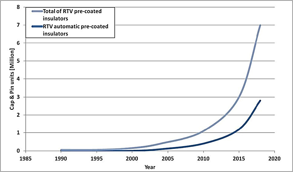
Since 2004, EKD has pre-coated more than 2,000,000 cap & pin insulators, of which more than half have been supplied to Terna. The remainder are installed on overhead lines in 50 countries. Similarly, factory-coated insulator production has evolved in parallel across the globe and it is believed that over 7 million such coated insulators are now in service as of 2019 (assuming that, in addition to those produced at EKD, another 4 million exist in China and a million more have been factory-coated in other parts of the world).
Conclusions
• A number of coating applications can potentially benefit the power industry by minimizing risk of flashovers on insulators, reducing corona losses and noise from conductors and fittings as well as avoiding corrosion and mechanical problems from ice and snow accretion on overhead networks. These also support environmental issues by reducing visual impact through camouflage of overhead power lines.
• A case history of successful application and evolution in RTV insulator coating technology is reported, with numbers of factory coated cap & pin insulators now growing exponentially to a total population estimated at about 7 million in service worldwide.
• This example suggests there remains room for improvement when it comes to coating applications involving other line components, not only in terms of greater efficiency but also in further increasing system reliability.

References
[1] U. Straumann1 and H.J. Weber “Potential reduction of audible noise from new and aged overhead transmission line conductors by increasing their hydrophilicity” Cigre paper B2_113_2010
[2] CIGRE WG D1-71 Understanding and mitigating corrosion CIGRE Brochure 765-2019
[3] K.J. Stevens et al. “Conductor Damage Inspection System for Overhead ACSR Power Cables CDIS on ACSR” 2013 Seventh International Conference on Sensing Technology
[4] ISA REP presentation “Problemática de Líneas Costeras”
[5] CIGRE WG B2.44 “TB 631Coatings for Protecting Overhead Power Network Equipment in Winter Conditions” CIGRE Brochure 631 2015
[6] D. A. Da Silva and S. A. Aslo Soto “Maintenance strategies of transmission towers on the Peruvian coast affected by salt pollution” ISH 2017
[7] N.H. Johnson “Camouflage of power lines to reduce visual impacts and enhance public Acceptance Cigre paper” C3_108_2010
[8] H. Lugschitz, A. Ernst, T. Gros “Corrosion protection of steel towers and camouflage of lines using the duplex-system” Cigre Paper B2 313 2004 session
[9] P. Graziosi “RTV silicone coating: Welcome from EKD! High Voltage Insulator Coating (HVIC): state of art and future developments – 11/12 October, 2018
[10] Terna Specification, “LIN_0000J116, REV.00 – Inspection provisions for High Voltage Insulators RTV silicone coated”, March 2012
[11] A. Pigini, P. Graziosi and S. Russo “RTV Insulator Coating: State of the Art and Research Needs” ISH Conference 2019
[12] Terna Specification, “INS CI S RTV, REV.00 – Application, inspection and certification provisions for RTV silicone coated High Voltage Insulators to be installed in electric substation”, January 2018