Application of composite-housed HV apparatus at substations has grown. This has particularly been the case for equipment such as instrument transformers where safe failure mode compared to porcelain is a crucial benefit. Expected performance and service life of polymeric housings compared to porcelain is of course a concern as well. If there are signs of premature ageing, it is important to know what remedial measures are available.
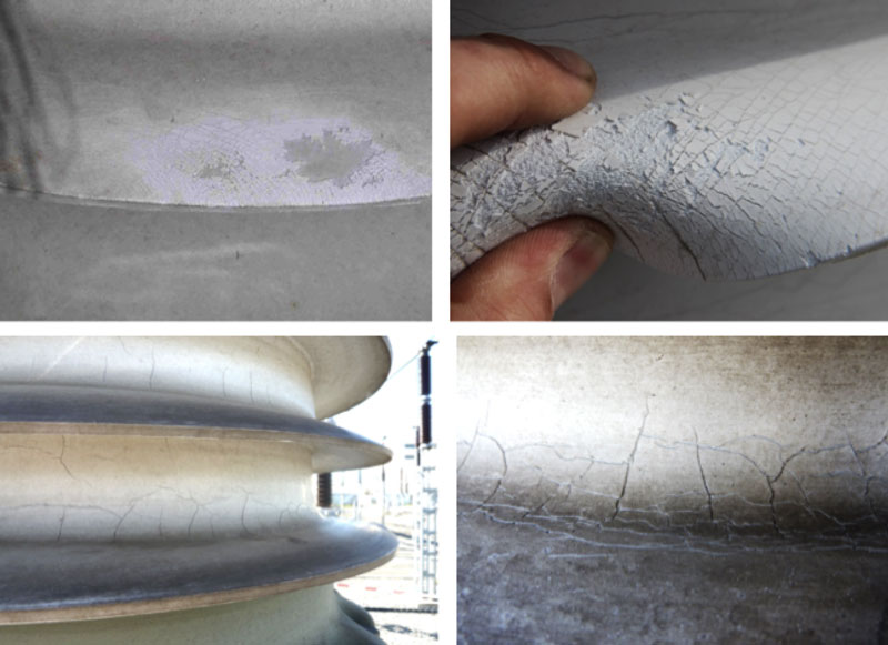
For example, past inspection of composite-insulated instrument transformers at substations in the Czech Republic revealed varying degrees of ageing of their housings. Degradation took the form of a hard surface layer that had become either hydrophilic or offered only poor hydrophobicity. There were also cases of more extreme degradation marked by spontaneous development of cracks on housing trunks as well as flaking of the surface.
This edited past contribution to INMR by experts at EGU HV Laboratory, the Czech Power System Operator (CEPS) and Lapp Insulators, discussed experience applying RTV silicone coatings to restore degraded polymeric housings.


Instrument transformers equipped with composite housings have been installed at 245 kV and 420 kV substations in the Czech Republic since 1992. These transformers are from a single manufacturer and have been operating in a temperate European climate where annual sun radiation ranges from 1300 to 1800h and temperatures drop to -30°C. All substations where these units have been put into service have low pollution exposure and pH values of local rain range between 4.2 and 4.9.
Regular inspection of polymeric housings on instrument transformers has revealed that degree of degradation does not always correlate with years in service. For example, some instrument transformers with only 5 years’ service suffered high housing degradation while similar transformers with a 20-year history showed no degradation. Moreover, there were cases when degree of housing degradation at the same substation and with the same number of years of service differed from one transformer to the next. This suggested that composition of all the polymeric insulating materials may not always be the same. In some cases, degradation along the length of the housing was distributed uniformly along the core as well as at the top and bottom of sheds. In other cases, degradation was evident on the top of sheds but hardly any on the bottom; or degradation was higher on the south-facing side of the transformer than on the shaded side, suggesting influence of UV. Finally, no difference in surface degradation between line and grounded ends of the transformer housing was observed, suggesting that this was not a problem caused by corona discharges.

Investigation of Degraded Housings
Results from measuring thickness of the degraded layer using Fourier Transform Infrared Spectroscopy (FTIR) and thermal gravimetric analysis as well as by studying the influence of acidic solutions and UV radiation were as follows:
• Maximum thickness of the degraded surface layer was up to 250 μm;
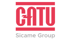
• Hydrolytic degradation of siloxane chains took place in the surface layer under typical service conditions. This process is connected with reduction in molecular weight and results in loss of physical properties such as strain and flexibility as well as formation of a non-flexible, brittle layer on the surface. While the degradation process starts and progresses from the surface, the inner portion of the housing remains unaffected up to a certain depth;
• Thermal stability of degraded samples after years of service fell within acceptable limits;
• Acidic solutions and UV radiation seemed to be factors linked to degradation;
• Degradation occurred along the entire surface of the housing. This suggests it could have been influenced by specific composition of individual batches of the silicone rubber used in manufacturing or by slight variations in production process.
Based on these findings, it seemed reasonable to assume that if a degraded housing surface remained unbroken by cracks, degradation reaches a certain thickness but then the surface is protected against further degradation. The degraded housing either becomes hydrophilic or only barely hydrophobic and such insulators have to be regarded as offering no hydrophobicity transfer, i.e. no ability to reduce surface conductance and leakage current activity.
If a degraded insulator has sufficient creepage distance, even though hydrophilic, such insulators can still provide the required service performance. This was confirmed during inspection by the fact that no erosion or tracking was recorded on housings having degraded surfaces. Moreover, three transformer housings with degradation were wetted under voltage. Corona camera inspection then showed no partial or corona discharges along their surfaces.
A much different situation could arise, however, should cracks develop in the degraded layer on the housing’s trunk. Due to internal tension in the polymeric material at this location, any cracks would remain open and degradation processes could continue. A similar situation could occur in the case of extensive flaking on the surface, where relatively large areas of virgin material become exposed to the environment. The most dangerous situation would be if cracks reached all the way into the equipment’s FRP tube. Moisture ingress and contamination of its internal oil or gas insulation would then become possible. In such cases, prompt measures to prevent further degradation would be necessary.

Types of Degradation
Surface degradation can be divided into two categories in regard to its potential impact on performance and reliability of apparatus:
• Type A Degradation
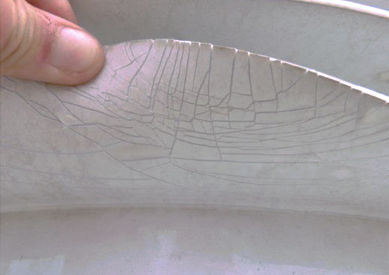
This is degradation without spontaneous development of cracks and where any cracks become visible only upon bending the insulation.
• Type B Degradation
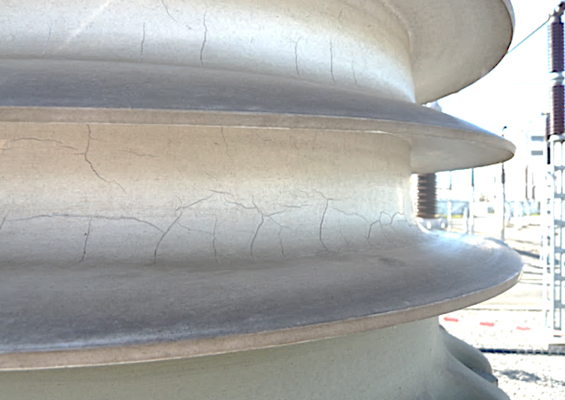
Here, degradation is marked by spontaneous development of cracks (e.g. on the insulator housing trunk) and/or extensive flaking of the degraded surface layer.
Type A Degradation
Fig. 2 shows examples of different degrees of Type A degradation.
Type A degradation does not constitute an immediate threat to service life and reliability of the transformer and it is sufficient to inspect any apparatus with this form of degradation every 4 years.
Type B Degradation
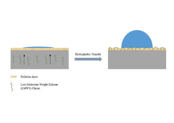
Fig. 3 shows examples of different degrees of Type B degradation.
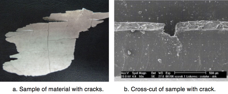
Samples of silicone rubber were cut from insulator housings with cracks on the trunk and subjected to scanning electron microscope analysis (see Fig. 4).
Type B degradation constitutes a potential risk to service performance. Therefore apparatus with this type of degradation should be inspected every year. Remedial measures were investigated to improve the surface condition of housings with such degradation.
Results of Maintenance Inspections
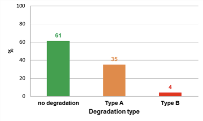
Instrument transformers with polymeric insulator housings that were in service at CEPS substations by 2015 had been manufactured between 1991 and 2007. In total, 300 such units were inspected, some repeatedly to monitor progress of degradation. Fig. 5 shows the proportion of insulator housings found to have experienced degradation.
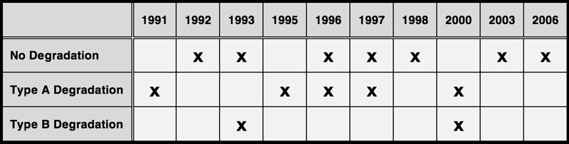
The main years of manufacture of apparatus with Type B degradation were 1993, 1995, 1999 and 2000. Fig. 6 shows the incidence and distribution of degradation, by type, at the substation with the highest number of instrument transformers.
Table 1 outlines dates of manufacture of the instrument transformers at this substation along with their respective types of degradation.
Measures to Restore Service Performance
Degradation on transformer housings inspected in 2015 had not yet reached a level that immediately threatened reliable operation. However, continuing Type B degradation, marked by development of deeper cracks on the trunk of the housing, could become dangerous. As a possible method to improve surface condition of housings with Type B degradation, application of an RTV silicone coating was tested on a sample cut from the shed of a degraded transformer housing. Half the sample was coated with RTV silicone while the other half was left uncoated. The sample was then subjected to 1000h accelerated ageing in a xenon chamber with UV radiation of 0.47 W/m2, 340 nm and with dry and wet cycle duration of 102 min and 18 min respectively. Fig. 7 shows that no further degradation was apparent on the coated portion of the sample after this test.
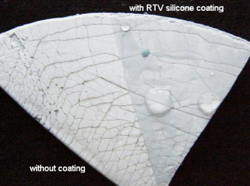
Moreover, adhesion of the RTV coating to the sample was the same as before the test. While the portion of sample with the RTV silicone coating again became hydrophobic, the part without coating was hydrophilic.
Experimental Coating of Polymeric Housings in Service
Experimental coating with RTV silicone was performed first on a 220 kV combined (voltage & current) instrument transformer with degraded housing. For this first application, a procedure was used that allowed monitoring and evaluation of:
• effectiveness and durability of the coating;
• influence of electric field;
• progression of degradation on the surface, both with and without the coating; and
• necessity to apply a primer before coating.
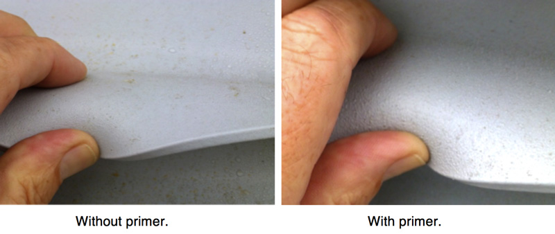
The RTV silicone coating was therefore applied to only two-thirds of the housing surface: the upper one-third at the line end and the lower third at the ground end. The middle section was left with no coating. Moreover, half the circumference of each coated section had a primer applied before the entire circumference was coated.
Coating Procedure
1. Surface Cleaning: Before coating, the surface of housing was cleaned with a hard brush to remove any unstuck parts of the degraded surface layer. Dust was removed with a wet cloth. The surface was then washed with a water/soap solution sprayed onto the surface. After drying, the rest of the surface contamination was cleaned with acetone.
2. Application of Primer: After the acetone evaporated, a primer was sprayed onto the selected parts of the surface. The goal was to find out if there is a difference in adhesion of an RTV coating to an aged housing surface with or without primer.
3. Coating: RTV silicone material was applied to the housing surface with airless spraying equipment. In total, there were 3 layers of silicone material such that between each layer application there was more than 30 minutes of drying time for solvent evaporation.

RTV Coating 220 kV Transformer Housing
RTV coating of an instrument transformer was performed in August 2014. Fig. 8 shows the state of surface degradation of the housing before coating.
A hard degraded layer on the top and bottom surfaces of sheds was found along the entire insulator housing. On some parts, cracking and minor flaking of the degraded surface layer had occurred and the entire housing was hydrophilic.
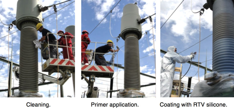
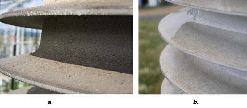
Fig. 10 shows the difference between parts of the housing with and without coating and Fig. 11 reveals the state of the surface and hydrophobicity of the coated housing portion.

Inspection of Transformer with RTV Coating
The first inspection of the instrument transformer with the RTV silicone coating was performed 10 months after coating. Fig. 12 shows the condition of the housing surface.
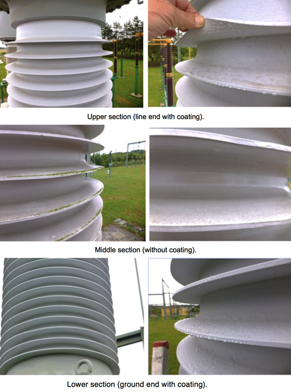
Results of the inspection showed that the layer of RTV silicone coatings on both sections (upper and lower) was without any damage and traces of surface degradation. Surface hydrophobicity of the instrument transformer housing parts with coating was excellent (HC from 1 to 3 according to IEC/TS 62073, cl. 6). The surface of the middle section without coating was totally hydrophilic. The adhesion of the RTV silicone coating on the degraded housing surface was excellent and there was no detectable difference in adhesion on the surface with and without primer (see Fig. 13).

RTV Coating 400 kV Transformer Housing
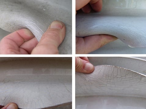
Coating a degraded 400 kV transformer housing was performed in July 2015. Here, the entire housing (upper and bottom parts of the sheds and trunk) had uniform degradation and was hydrophilic. Spontaneous development of cracks as well as flaking of the degraded surface layer were investigated and it was discovered that the flexibility of sheds had been reduced (e.g. cracks occurred even with minor bending). Fig. 14 shows the extent of surface degradation.
Coating the housing was performed from a scaffold built around the transformer. To shield the work area from wind, the scaffold was protected using plastic tarps (see Fig. 15).
The coating procedure was basically the same as used for the 220 kV transformer but now without application of primer. Fig. 16 shows the state of the surface and degree of hydrophobicity of the coated housing.
Summary & Conclusions
Degradation of the surface of polymeric housings on instrument transformers was observed during routine maintenance. Degradation typically took the form of a hard surface layer up to 250 μm in thickness. The surface with this hard layer had become either hydrophilic or much less hydrophobic than when new. Follow-up inspection indicated that degree of degradation was not dependent on duration in service. Moreover, degradation of the same type of apparatus from the same producer and the having the same time in service was different from one transformer to the next – even at the same substation. This degradation had to be caused by some combination of environmental conditions (e.g. pollution, UV, etc.) and/or variations in the properties of the polymeric housing material (e.g. composition of different batches) or changes in manufacturing processes. In most cases, the hard surface layer cracked only when sheds were subjected to bending. Moreover, if the thick, hard degraded layer occurred uniformly along the top and bottom surfaces, sheds lost elasticity and even small bending led to cracking.
If a housing has sufficient creepage distance, service performance and reliability of apparatus with surface degradation (but with no spontaneous cracking) would not be immediately affected. Spontaneous development of cracks, e.g. on the housing trunk, and/or flaking of the degraded surface layer were observed on only some transformer housings. Under such degradation, performance of the apparatus could decrease and measures to restore reliability would have to be considered.
Applying an RTV silicone coating to polymeric housings with a high degree of degradation (e.g. marked by spontaneous development of cracks on the insulator trunk) is one way to increase reliability. The coating can be sprayed directly onto the cleaned, degraded housing, without need for prior application of primer. The RTV material fills the surface cracks and restores hydrophobicity of the previously degraded polymeric housing but cannot restore elasticity to sheds.