The primary goal when installing metal oxide surge arresters (MOSAs) at substations and on transmission lines is to limit lightning and switching induced overvoltages to some specified protection level. In this regard, arresters are required to absorb energy associated with overvoltages.
This edited past contribution to INMR by Robert Le Roux of Ireland’s Electricity Supply Board (ESB) in co-operation with Paul Leufkens of Power Projects Leufkens reviewed the latest developments in HV surge arresters based on work conducted within CIGRE Working Groups A3.25 and A3.39. In general, these developments were driven by the need for increased safety and reliability. In addition, over the past 10 years, expansion of DC grids and AC grids of Um=800 kV and higher has called for new MOSA designs. Moreover, while a recent study in North America found that the 69 kV to 550 kV arrester market is driven mostly by replacement, with life cycles of more than 30 years, there are also growing new applications, such as GIS, substation bus and cable installations.

Reliability Surveys & Measures
CIGRE WGs A3.17 and later A3.25 addressed a variety of topics relevant to reliable design and operation of surge arresters. The focus has been on energy handling capability of their MO resistors when stressed with repeated and multiple current impulses of different wave shapes and changing polarity. For example, one finding was that the sum of the mean failure energy of MO resistors up to mechanical failure (or according to a more specific ‘complex failure criterion’) for single long duration current energy injections was equal to that for double long duration current energy injections with intervals of up to 3s between the two impulses. It was further concluded that energy injections with high current impulses of short-wave shape 4/10μs and high current density can lead to a significant change in ‘characteristic voltage’, Uch. This, however, does not seem to affect energy handling capability of MO resistors in a measurable way.
This same study mentioned that, while for most AC system voltages surge arresters are now basically ‘standard’, some requirements need special consideration. Concerns involve:
• excessive height (e.g. more than 10 m) resulting in axial voltage, power and temperature imbalance effects – apart from mechanical problem;
• required low switching impulse protection level resulting in high energy handling requirements;
• huge number of MO resistors requiring very low failure probabilities of individual units during energy injection; and
• limited protection distance because part of the typically provided protection distance is actually being used by the arrester and its installation.
A completely new classification system for MO surge arresters has also been introduced whereby the former Line Discharge Classes (LDC) has been replaced by the new concept of charge transfer and energy handling schemes.
Reliability of substation power equipment has always been a concern to transmission and distribution system operators since failures could mean significant outages with associated power restoration efforts and safety implications. Moreover, apart from the cost of a system outage and its restoration, poor reliability contributes to higher operating and maintenance costs. For such reasons, CIGRE periodically conducts reliability surveys on power equipment to obtain feedback on validity of international standards. The 4th such survey on substation equipment is now in progress and its scope has been expanded to include surge arresters. Table 1 shows data on populations and major failure frequencies of metal oxide surge arresters (MOSA) as a function of voltage rating. Note that Countries B, C and E reported no major failures between 2014 and 2017.
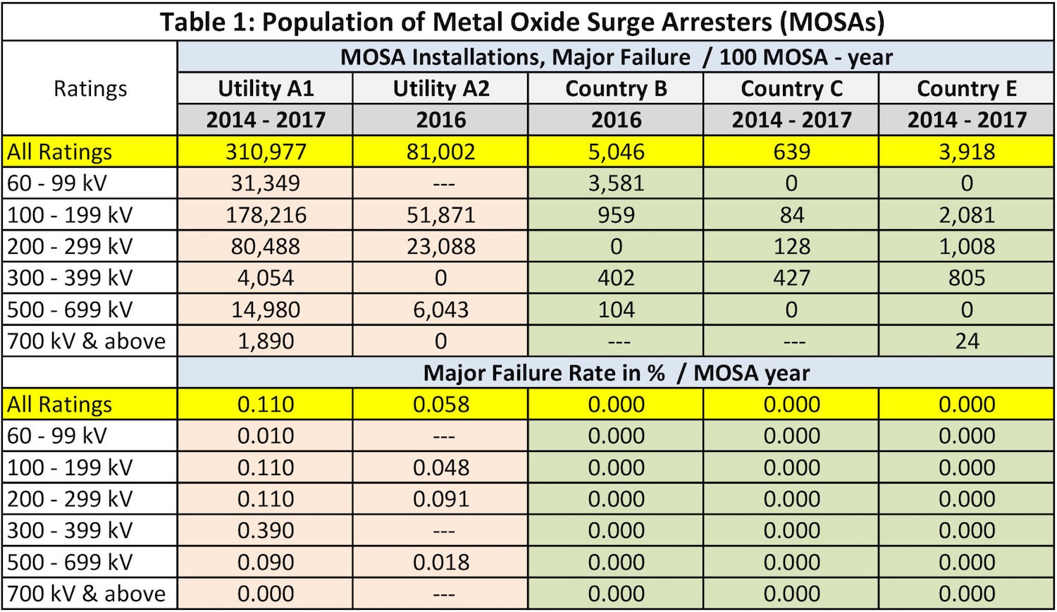
Two utilities from Country A reported failures but these involved mostly a series connected MOSA installed in EHV and UHV power systems and applied to protect series capacitor banks. There, MOSA design is multi-column type to cope with required high energy absorbing capacity. CIGRE WG A3.39 is still investigating such field experience and working to provide more detailed results on MOSA reliability along with relevant background information. Japan, for example, is one of the countries that participated in the reliability survey to better understand how well actual field stresses are covered by present requirements on MOSAs. As of mid 2017, some 32,000 MOSAs with system voltage higher than 66/77 kV and up to and including 500 kV were in operation, with over half being more than 25 years in service. Fig. 1 presents failure statistics from the survey, where major failures are defined as requiring urgent replacement versus minor failures where function remains available.
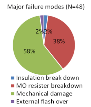
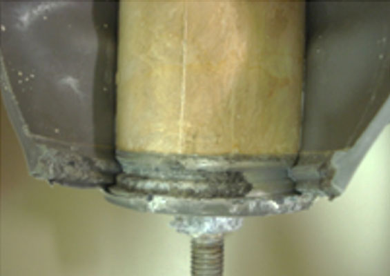
Total number of reported MOSA failures was 177, comprised of 48 major and 129 minor failures. Frequency of major failure was determined to be 0.007 cases/100 unit-years, considered low by comparison with other international data. 58% of these major failures were due to mechanical damage to the porcelain housing from earthquake while 38% related to breakdown of MO resistors due to energy handling capacity being exceeded, leading to internal arc. Given that resilience against seismic phenomena is so important, a special standard has now been issued to prevent serious damage to equipment and electrical outages due to severe seismic events. JEAG 5003 defines ‘300 gal resonant 3 cycle sine wave sudden input’ as the seismic design requirement for equipment with porcelain insulator housings. Other conclusions from the Japanese survey were that standardization contributes to more streamlined manufacturing and improved substation design. Similarly, it is worthwhile improving detection of degraded MOSAs before failure.

Low Residual MOSAs
Overvoltage protection is a key issue for power systems. This is particularly true in the case of 1000 kV UHV AC systems given that transient overvoltages subject insulation to great levels of stress and make it challenging to construct such systems. Generally, switching overvoltages play a greater role than lightning surges in determining insulation level with increasing operating voltage. For example, according to insulation coordination requirements in places such as China, switching overvoltages for UHV systems are expected to be reduced to 1.6 – 1.7 p.u. (phase-to-ground). However, this level is still so high that UHV equipment is both costly and difficult to manufacture. Although rated voltage of a 1000 kV UHV system represents only a 33% increase versus 750 kV, prices of power apparatus for them typically increases several-fold and even up to 100 times higher.
Solution to Key Problems
Some components can be designed to resolve switching overvoltage challenges:
• Multistage closing resistors
Although a good solution for switching overvoltages, problems with the multi-stage closing resistor are that it is a complex device and easily damaged, with resulting low reliability, high expense and frequent supply shortage. Together, failures and lack of supply can mean extended outages.
• Controlled closing resistor
Like the multistage closing resistor, this is a complex solution. Still, it offers superior reliability to the multistage closing resistor even though also very costly. A closing resistor will absorb large amounts of energy.
• Installing arresters along the line
Utilizing presently available arresters offers some limited effect even though highly reliable and relatively inexpensive.
MOSA Developments
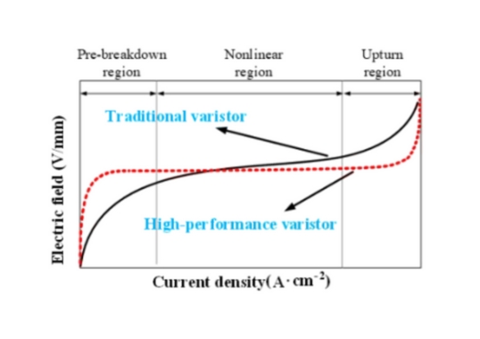
A low voltage ZnO varistor is one of recent developments aimed at improving the V-I characteristic to obtain better non-linearity and lower residual voltage. That would serve to increase the voltage gradient in the pre-breakdown region and decrease residual voltage ratio in the upturn region. Fig. 2, for example, shows how addition of special dopants can shift the full line to the left, thereby improving voltage gradient in the pre-breakdown region. New materials, such as Ga2O3 and Al2O3, are added to the traditional formulation and improved sintering technology is also adopted, whereby the material is milled to a finer, more consistent grade. Some special dopants, which include elements such as bismuth and manganese, affect discharge voltage while others play a role in power loss, ageing behavior, energy absorption etc.
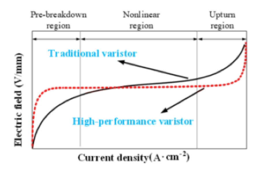
The significance of improved voltage gradient is quickly evident. For example, height and weight of arrester can be reduced versus existing MOSAs to meet requirements for a smaller arrester for higher voltage applications. Moreover, with improved manufacturing process and disk selection, a more consistent arrester can be produced, resulting in equalized voltage distribution across the unit. This not only yields better reliability and ageing profile that is consistent over a bank of MOSAs but also simplifies arrester structure with reduction in both size and cost.
Application Conclusions
Cost and insulation requirement can be reduced due to smaller MOSAs while safety is increased as a result of improved linearity and reduced overvoltages. Required reduction of about 30% in switching and lightning overvoltages becomes possible along with size reduction of more than 50%. This would allow using 750 kV MOSAs for 1000 kV system applications and 220 kV MOSAs on 330 kV systems.

Controllable Metal Oxide Arresters
EHV/UHV AC transmission techniques have been developed to meet the need for long-distance, large capacity transmission networks and global energy interconnections. But existing measures to reduce switching overvoltages have shortcomings since, as transmission voltages becomes higher, switching overvoltages also increase and put equipment at greater risk. Moreover, using complex closing resistors, the framework of circuit breakers also becomes more complex and many accidents occur when the closing resistor disintegrates or the mechanism fails. Such accidents pose great risk to networks while equipment costs rise substantially with installation of closing resistors. Reducing line length and thereby MOSA rated voltage as well allows reducing switching overvoltage however MOSA charging current increases. This accelerates ageing of MOSAs, which again is a drawback due to reduction in reliability.
Proposal for Controlled MOSAs
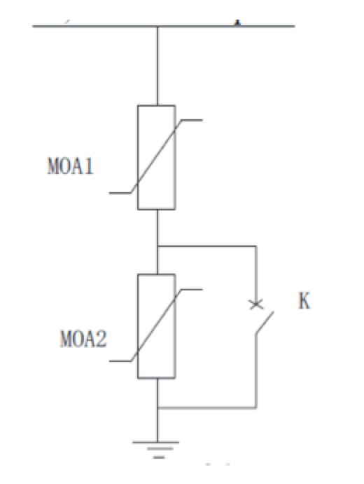
One suggested method to resolve this problem is to have a controlled MOSA. The principle of operation involves spliting the MOSA into two sections: one a normal section; the other a controlled section. During normal system operation, the two MOSAs act together to withstand power frequency and lightning overvoltage. The controlled section is where the second section is by-passed with a switch. During a transient situation such as switching overvoltage, K is closed, shorting MOSA 2 and reducing residual voltage over the MOSA. Operational area of the switch is determined by level of overvoltage (see Fig. 3).
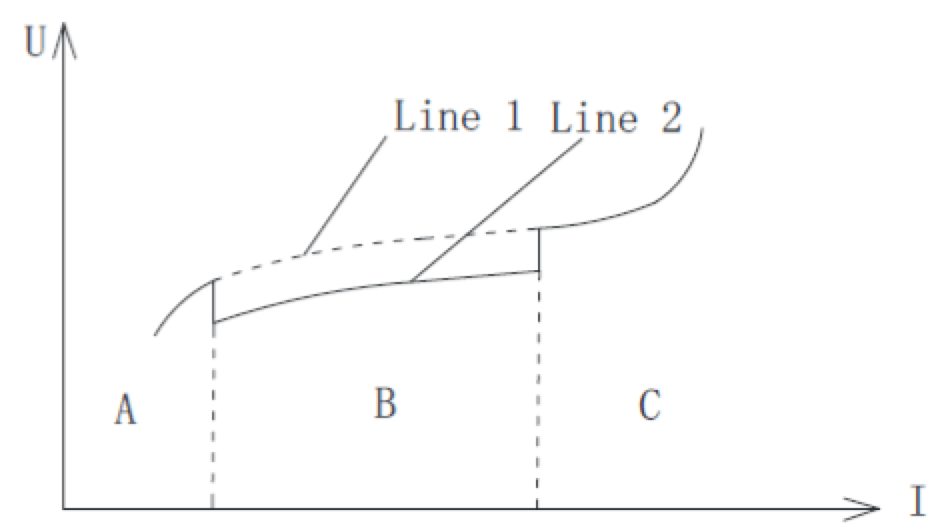
A – Power Frequency Voltage and Overvoltage / B – Switching Overvoltage / C – Lightning Overvoltage
This technology was tested in 2016 for functionality and reliability at the Wuhan UHV AC Test Centre in China.
Parameter Selection & Control Strategy
Ratio of control is determined according to line length as well as through experimentation. For example, a level of 15% was determined for lines of 250 km or less with levels of between 15 and 20% for longer lines. That means that a section of 15% is switched in or out, as shown in Fig. 4. The control switch, called K for now, needs to be selected to operate safely at the set threshold and reliability needs to be verified. This equipment, being new and much different from conventional MOSAs, will require development of new test methods.

Technology Application
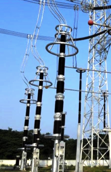
This new technology was recently first installed on the Beijing West to Shijiazhuang Extension Project (see Fig 5).
Application of this technology means that size and weight of associated circuit breakers can be reduced since reduction in residual voltages means no further need for closing resistors, which are large and complex. While cost of the controllable MOSA section increases by about 50%, total breaker cost, representing the major proportion of overall cost, can be lowered by more than 30%. Net result is cost savings.
Other Developments
HVDC & Long Line AC Applications
With the rapid increase in HVDC connections worldwide that use newer Voltage Sourced Converter (VSC) technology, there is growing demand for effective circuit breakers, as for transfer switches – especially as more and more original point-to-point DC connections become interconnected. In this regard, there is growing need for MOSAs able to absorb the inductive energy that comes with switching-off or transfer switching of loads of such connections. Since an HVDC system is highly complex and contains many power electronics components, numbers of MOSAs and their insulation coordination ranking are high compared to AC.
In the case of long AC lines, there is also demand for MOSAs better able to protect series capacitor banks especially against line faults. Traditional MOSAs can absorb only about 200-400 J/cm3 to prevent mechanical and electrical degradation. That means that large volume arrangements of MOSA columns are needed to cope with the energy that has to be taken out of the system. Moreover, special attention has to be taken to match the parallel columns given that MOSAs have strong non-linear voltage-current characteristics. It seems clear that MOSAs can be highly effective in providing protection to electrical systems for series compensation as well as for HVDC circuit breaker applications.
Application of Surge Arresters in Mitigating Breaker Transient Recovery Voltage
MOSAs can be effectively used in parallel to circuit breakers to reduce Transient Recovery Voltage (TRV) peaks sufficiently to avoid overstressing CBs and, depending on situation, to avoid using CBs with more chambers in parallel. But initial rate of rise of TRV (RRRVs) cannot be attenuated with MOSAs. Moreover, issues can arise from utilizing this method. Additional space is required in the substation for installation of MOSAs and determining area of responsibility is also needed, especially if MOSA and CB are supplied by different manufacturers.

Miscellaneous Trends
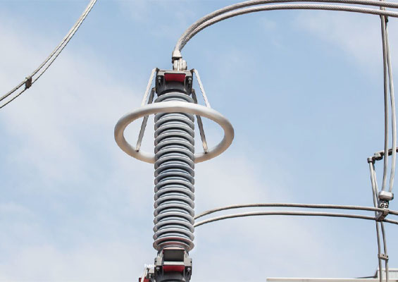
Other developments underway in regard to MOSAs include: leakage current monitoring, surge counters, on-line monitoring of arrester leakage current, compact surge arresters, especially for GIS, and dead-front arrester designs.
Summary
MOSAs are installed at substations and on transmission lines with the purpose of limiting lightning and switching induced overvoltages to a specified protection level. Surge arresters are fundamental to absorb the energy associated with overvoltages. Over the past 10 years the introduction and expansion of DC and AC grids of Um = 800 kV and higher has called for new designs of MOSAs. In all these functions MOSAs need to be highly reliable. The 4th CIGRE Reliability Survey on Equipment has, for the first time, also covered experience with surge arrester. The finding has been that MOSAs generally show good service experience and are stable in performance over an expected service life of more than 30 years.
Important developments include: low residual voltage MOSAs are being created to improve the V-I characteristic to obtain better non-linearity by increasing voltage gradient in the pre-breakdown region and decreasing residual voltage ratio in the upturn region. Reduction of about 30% in switching and lightning overvoltages then becomes possible with size reduction of more than 50%. Another development is to put controllable metal oxide arresters on the line side of a substation and combine the conventional arrester in the middle of transmission lines, in order to depress switching overvoltage and cancel the closing resistance of the circuit breaker. Using this technology means that size and weight of the associated circuit breaker can be reduced. Due to reduction in residual voltages, there is no further need for complex and large closing resistors. Other new applications with growing success are application of MOSAs in HVDC circuit breakers as well as in AC breakers with more chambers in parallel to reduce TRVs.

Bibliography
[1] North American Station Class HV Surge Arrester Study – Newton-Evans Research, November 2018
[2] Metal oxide resistors and surge arresters for emerging system conditions – introduction to CIGRE Technical Brochure 696 by WG A3.25 – ELECTRA No. 294 page 41 to 53 – October 2017
[3] Moritz Gießel, Volker Hinrichsen, Reinhard Göhler, Yvonne Späck-Leigsnering, Erion Gjonaj, Herbert De Gersem: Electro-Thermally Coupled Finite-Element Simulations of High Voltage Station Arresters with and without Grading– INMR Barcelona-Sitges, Spain, Nov. 5-8, 2017 INMR WORLD CONGRESS
[4] Hiroki Ito, Nenad Uzelac, Franck Richter, Robert le Roux, Wayne Paper, Li Peng, Anongpun Man-Im, Ioan Hategan, and Koji Kawakita: CIGRE Reliability Survey on Equipment – CIGRE Condition Monitoring, Diagnosis and Maintenance, CMDM Romania Colloquium September 9th to 11th 2019
[5] S. Yuasa, H. Iwane, T. Watanabe, M. Kosakada, H. Kajino: Application and Reliability of Metal Oxide Surge Arresters in Japan – CIGRE 2018 paper A3-206
[6] Kick-off meeting C4/A3-53 Hong Kong – 11 June 2019
[7] X.CHEN, W. SHI, Z. HE, H. YU, Z. LI, W. CHEN, D. GE, X. HAN, G.SUN, M. LI: Flexible measures to depress switching overvoltage in UHVAC transmission system and latest research results. CIGRE Paris 2018, paper A3-106
[8] Robert le Roux, Stuart Roche, Nadew Belda: Utilization of Metal Oxide Surge Arrester in HVDC Circuit Breaker and similar applications -– Paper no 117 at International Conference on CMDM, September 9th -11th 2019, Romania
[9] AMON J. F., GONÇALVES R. A. A.: Application of MOSA in parallel with Circuit Breaker’s chambers as a possible solution to TRV – CIGRE Paris 2018 paper A3-101