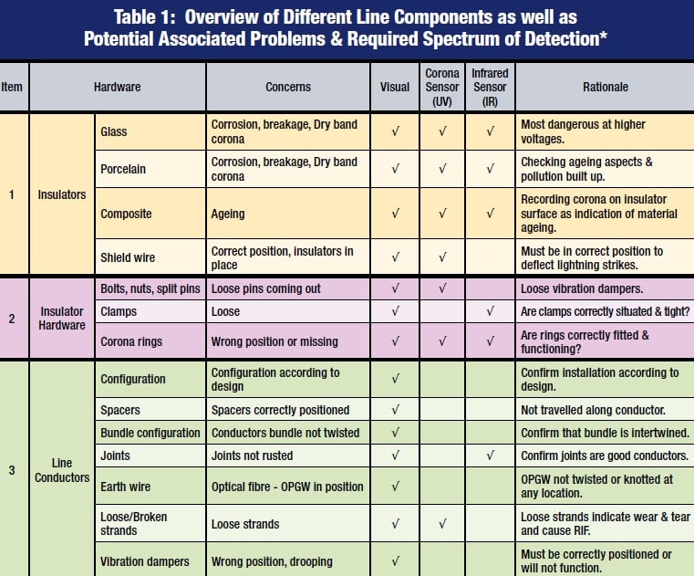
A key issue in maintenance of power networks is understanding what is being revealed during ultraviolet and infrared inspections of equipment and hardware on overhead lines and at substations. Do the two technologies highlight the same problem or are they rather complementary, each revealing a different aspect of the problem? Moreover, is it correct to assume that every different potential defect carries some unique ‘signature’ and therefore requires its own specific inspection technology?
This edited past article, contributed to INMR by Roel Stolper, an expert in diagnostics from South Africa, aimed to address these questions.


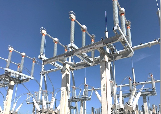
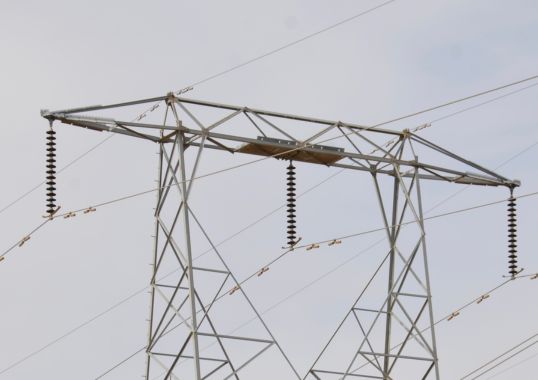
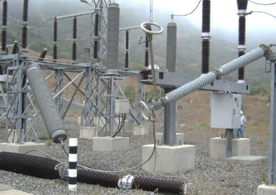
Typical Problems on Lines
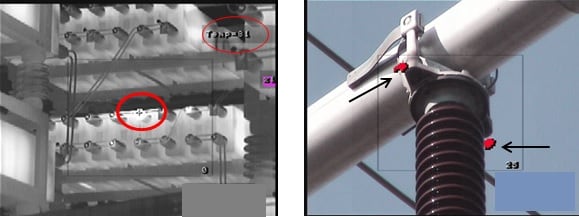
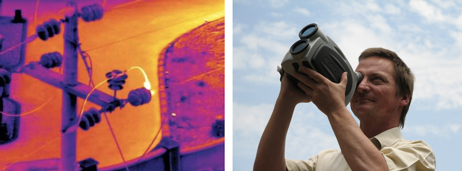
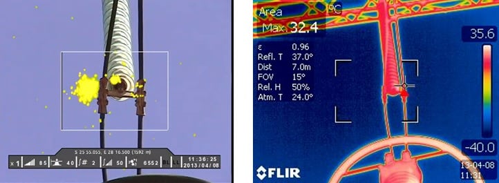
(Right) Fig. 3: Bus bar clamp with corona discharges.
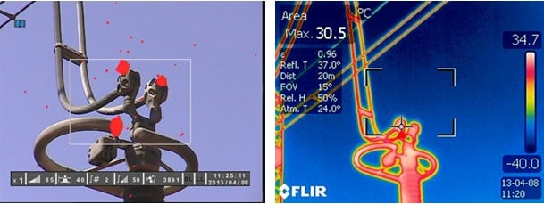
(Right) Fig. 4b: Infrared recording of same object.
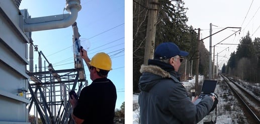
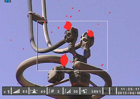
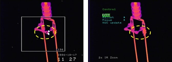
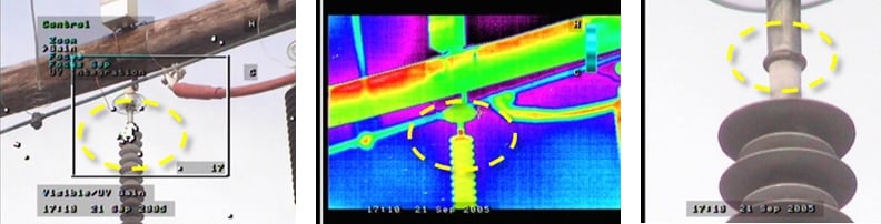
(Right) Fig. 6: Ultraviolet corona camera inspection.
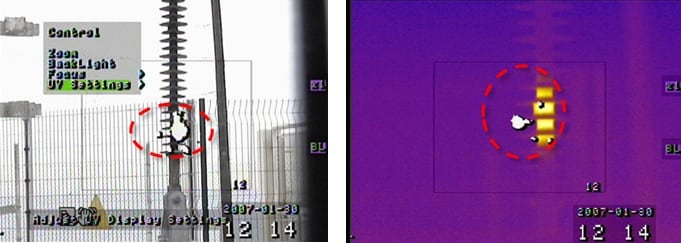
(Right) Fig. 8: Combined ultraviolet, infrared and visible camera inspection.

Current Inspection Technologies
Years of experience in line inspection have indicated that there is still no single technology that best meets every need. Moreover, no diagnostic sensor will detect and locate all possible different faults that can appear on a line. Given this, it is correct to state that the ideal inspection tool is one that integrates different types of sensors into a single instrument. Generally speaking, modern inspection technology can be classified into two main groups: ultrasound radio telescopes and camera detectors. Both make use of the basic phenomenon that any defect will emit radiation (i.e. energy in the electromagnetic spectrum) that can be detected and recorded by an inspection device.
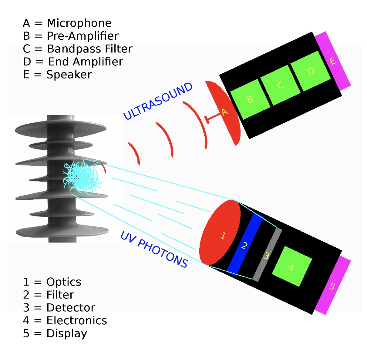

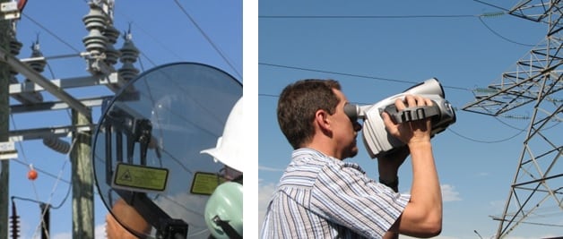
Basic Principle of Ultrasound Detectors
A round dish focuses ultrasound radio waves onto an RF detector (microphone) that amplifies and presents any weak signal detected to the operator by means of sound produced by an earphone
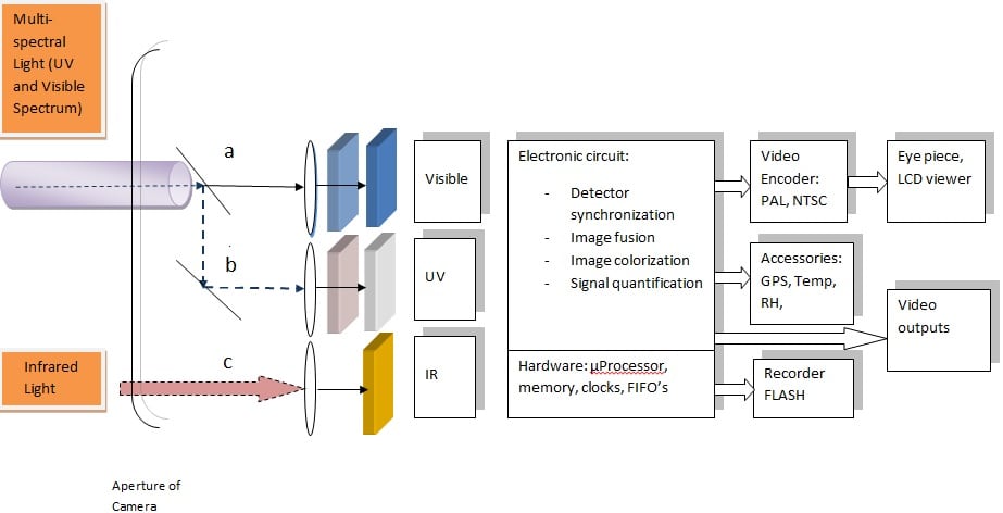
Basic Principle of Camera Detectors
Light from a source is collected by a lens, projected through a filter onto a detector that converts the light energy into electric signals. The signals are electronically manipulated into a raster image and displayed to the operator.
(Right) Fig. 11: Multi-spectral camera system.
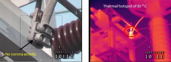
(Right) Fig. 13: Thermal image showing slight heat source.
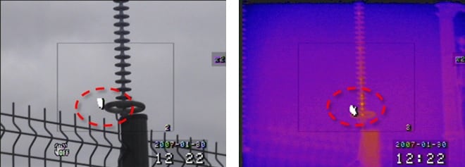
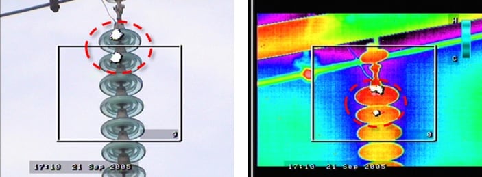

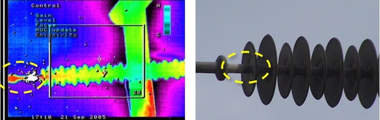
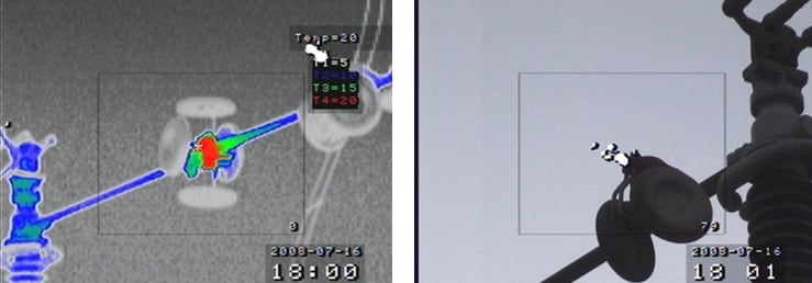
The images in Figs. 12 to 20 are from ultraviolet and infrared camera recordings of electromagnetic radiation related to unique defects occurring in line components. For example, a simple structural defect (e.g. a cut in a silicone insulator housing or a damaged ceramic disc) generates corona activity due to distortion of and increase in electric field. Similarly, an internal defect in a composite insulator can result in leakage current along the FRP core rod, causing heat dissipation. Viewed this way, it is clear that corona and thermal cameras are essentially complementary and that no single inspection technology is inherently superior. One can therefore also conclude that, ideally, IR and UV inspection should be conducted simultaneously. To demonstrate, Fig. 14 shows ultraviolet and infrared recordings of the same object. There is only corona activity present due in this case to sharp edges on the clamps. But there is no heat dissipation, suggesting that corona does not necessarily generate heat. Fig. 15 shows a defective polymeric insulator with corona activity at the sheds as well as internal defects that produce heat.

Ultraviolet/Infrared Inspection with Single Device
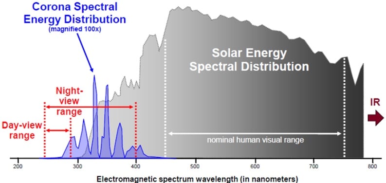
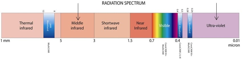
Corona discharges are detected using an ultraviolet detector that converts ultraviolet radiation to the wavelengths that can be seen by the human eye. This same principle applies to infrared heat radiation detected by the IR uncooled micro-bolometer and subsequently converted to wavelengths in the visible spectrum. In simple physical terms, corona is plasma discharge whenever ambient gases are ionized. During the subsequent de-ionization phase, photons are emitted with emission lines related to the spectral properties of these gases. Air is made up of about 80% nitrogen, which has its dominant spectral lines in the UVA and UVB spectrum and minor lines in the UVC spectrum. The spectrum where corona radiation appears is shown in Fig. 21.
In regard to heat radiation, any material emits at a wavelength that depends on body temperature, its so-called kinetic surface energy. According to Wien’s displacement law, peak wavelength, λmax, is at 2898/T, where λ is expressed in micrometers (1.10-6) and T is temperature in degrees Kelvin. Simple calculation reveals that a body at 27°C emits peak radiation at 10.55 µm such that, for example, a clamp at 100°C will have maximum radiation at 7.76 µm.
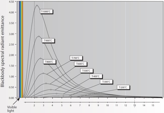

Calculation shows that, for any line inspection application where there are only low temperature sources, a heat detector is required to convert radiation at 8-10 µm wavelengths into the visible spectrum. There are a number of heat detectors available on the market and these are classified according to spectral sensitivity as determined by material composition of the detector.
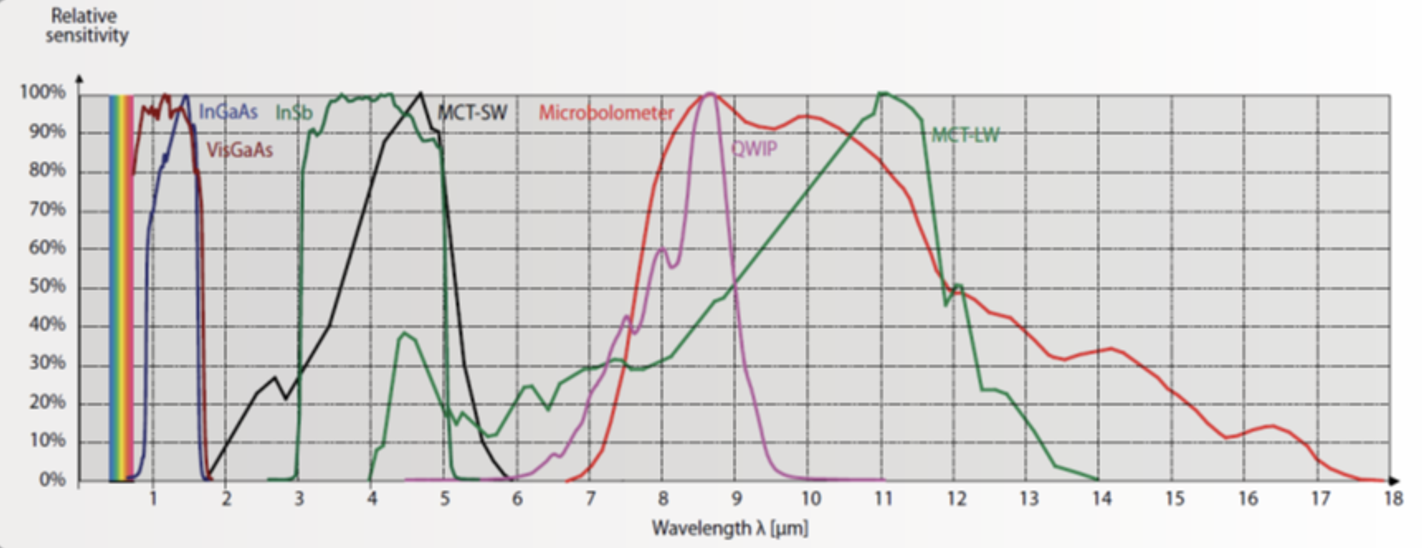
The mercury cadmium telluride (MCT) and Quantum Well (QWIP) detectors, for example, are relatively expensive since Sterling engines are required to cool them to -70°C. The micro-bolometer detector, by contrast, is used by many camera manufacturers for industrial infrared inspections. This type of detector does not need cooling and works at room temperature. It is also compact with high pixel resolution, low cost and easy availability. Fig. 25 depicts the operating principle of a multi-camera, combining all inspection technologies, i.e. visible, infrared and ultraviolet and Fig 24 shows the spectra where it will operate.
Conclusions
UV and IR inspection are not simply two alternative ways to look at the same problem. Instead, each inspection technology records a particular type of defect or abnormality within the component or equipment being inspected. In general, it can be said that ultraviolet recordings indicate the presence of corona activity while infrared recordings highlight heat phenomena. Moreover, UV corona recordings have to do with surface discharges and indicate the presence of high electric field. By contrast, infrared measurements highlight presence of leakage current. The first phenomenon depends on surface condition while the second depends on an internally generated heat source.
The latest developed multi-spectral cameras enable the power industry to simultaneously inspect electrical equipment for corona discharges and infrared hotspots. Specialized software assists the user to record, process, store and retrieve these recordings.