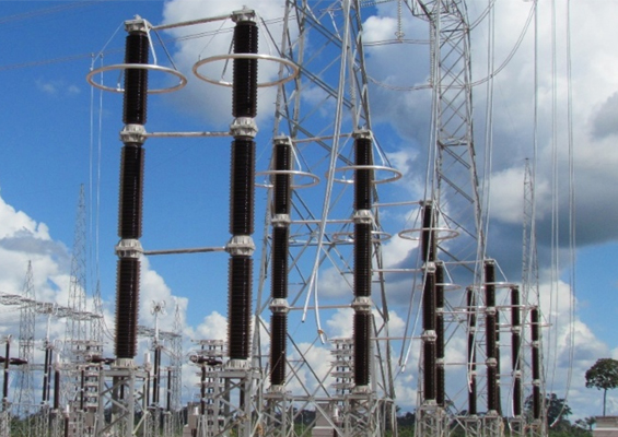
Transmission line surge arresters (TLSAs) are applied on overhead lines to improve outage performance and, particularly at EHV, to limit magnitude of switching overvoltages. There are two basic types – externally gapped (EGLAs) and non-gapped line arresters (NGLAs). NGLAs are comprised of a column of metal oxide varistors (MOVs) packaged in a fiberglass-reinforced polymeric housing and are installed between phase conductors and towers using connection leads. One end is typically fitted with a disconnector to break the electrical connection in the event of arrester failure. Installation configurations fall into three broad groups: Mounted onto tower structure or hung from a cross-arm; hung from conductor; or installed in parallel to line insulator as part of the insulator assembly
Service experience has shown that, from the electrical point of view, application of NGLAs typically improves line performance with relatively few failures. Nonetheless, utilities have reported that installations are sometimes compromised by mechanical issues such as failure of connection leads or disconnectors. While arrester standards do not include mechanical tests or requirements for the connections, IEC 60099-5 suggests an arrester life expectancy of at least 25 years. Given these considerations, EPRI began a research project to better understand causes of lead breakages so that necessary functional improvements could be included in future user specifications.
This edited past contribution to INMR by experts at EPRI reviewed findings and offered insight into requirements for mechanical testing, with focus on NGLAs since these are the type most commonly applied in the United States.


NGLA installations should be designed to minimize mechanical stress on connection lead and disconnector since these components (and the disconnector in particular) are generally not able to tolerate high mechanical loads. Other important mechanical design considerations are:
• Connections should allow free movement of phase conductors, which can take the form of conductor swing, Aeolian vibrations, galloping and sub-span oscillations;
• Connections and associated hardware should withstand all mechanical forces to which they are subjected;
• Connections must be durable enough to withstand fatigue due to movement;
• Installations and connections should not place excessive mechanical loading on the arrester or on disconnector attachments;
• Arrester disconnection should occur in a controlled manner, without consequential damage to the unit or to other equipment.
Lead wires are used to connect an arrester unit to the phase conductor or to a grounded part of the line support structure and there are two types of lead configurations:
1. Flexible rope type wires with crimped lug connectors
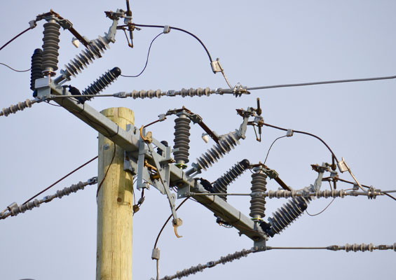
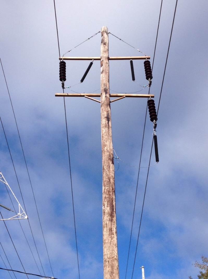
These configurations are mostly used in applications where the lead is not subjected to high mechanical loads (as in Fig. 1).

2. Chain intertwined with lead wire
These configurations have been successfully applied in cases where significant mechanical loads are expected.
Since the primary function of the lead is to establish an electrical connection, it should be designed to carry (a) low magnitudes of continuous current flowing through the arrester during normal operation; (b) high impulse discharge currents when the arrester conducts a surge; and (c) power frequency fault current if the arrester fails. Since the lead also implicitly establishes a mechanical connection, it is also necessary to consider these mechanical forces when designing the lead attachment.
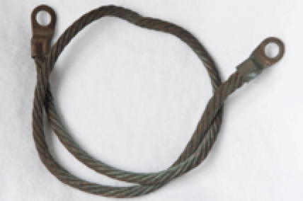
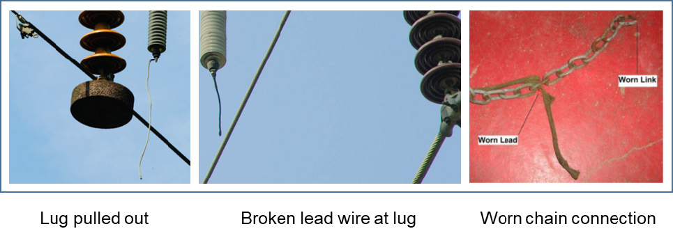
Fig. 2 shows examples of common lead failures, which include:
• Lead wire pulling out of the lug, a common problem and possibly the result of mechanical overload or poor crimping of the lead connection;
• Edge of the crimped lug ‘sawing’ into the lead conductor thereby severing strands and mechanically weakening the lead, such as when a mechanically loaded lead is not aligned with the lug;
• Chain connections where the electrical lead connection woven through the chain wears down due to continuous lead movement.

Load Characterization Testing
Current standards do not provide guidance specific to applying line arresters nor do they prescribe mechanical tests for leads. Therefore, with the goal of developing suitable laboratory test methods for leads and disconnectors, EPRI constructed a simulated field test to quantify typical in-service mechanical lead loads under different environmental conditions. The simulated field test measures mechanical loading of the arrester and leads under actual service conditions while also monitoring and recording any mechanical degradation on the components. This information then provides a good basis for subsequent laboratory testing.
Instrumenting an energized installation was not cost justified in this case since only the mechanical forces on the lead are of interest. Three typical arrester configurations were therefore installed on a de-energized test line commissioned at EPRI’s High Voltage Test Facility in Lenox, MA in Jan. 2015 (see Fig. 3). Mechanical loads in the leads are monitored continuously but only maximum load over a 2-minute interval is logged. Special precautions were taken to ensure load cells and their added weight did not influence the loads in the leads. A dedicated weather station was used to continuously reconcile impact of the outdoor environment during testing and backed up by another logging weather station attached to a mast only a short distance away. The most important parameter, wind speed, is monitored with a 2-D ultrasonic type anemometer, which has no moving parts to wear out or to introduce errors from drag. Ultrasonic anemometers have the further advantage of more accurately measuring lower wind speeds.
Load measurements taken over an 18-month period for each of the three arresters were then compared and data from the position experiencing the highest loads was reduced to a simplified test cycle. An acceleration factor was achieved by applying loads at much shorter time intervals (16 hours of testing equivalent to one year of service life). The original intent was to develop a test that enabled accelerated ageing of just the arrester leads. However this was later extended to mechanical testing of the arrester body as well.

Accelerated Ageing Testing
To simulate tensile forces in arrester leads, a test rig was built enabling a series of load cycles to be applied precisely to the leads and hence the arrester body (see Fig. 4).
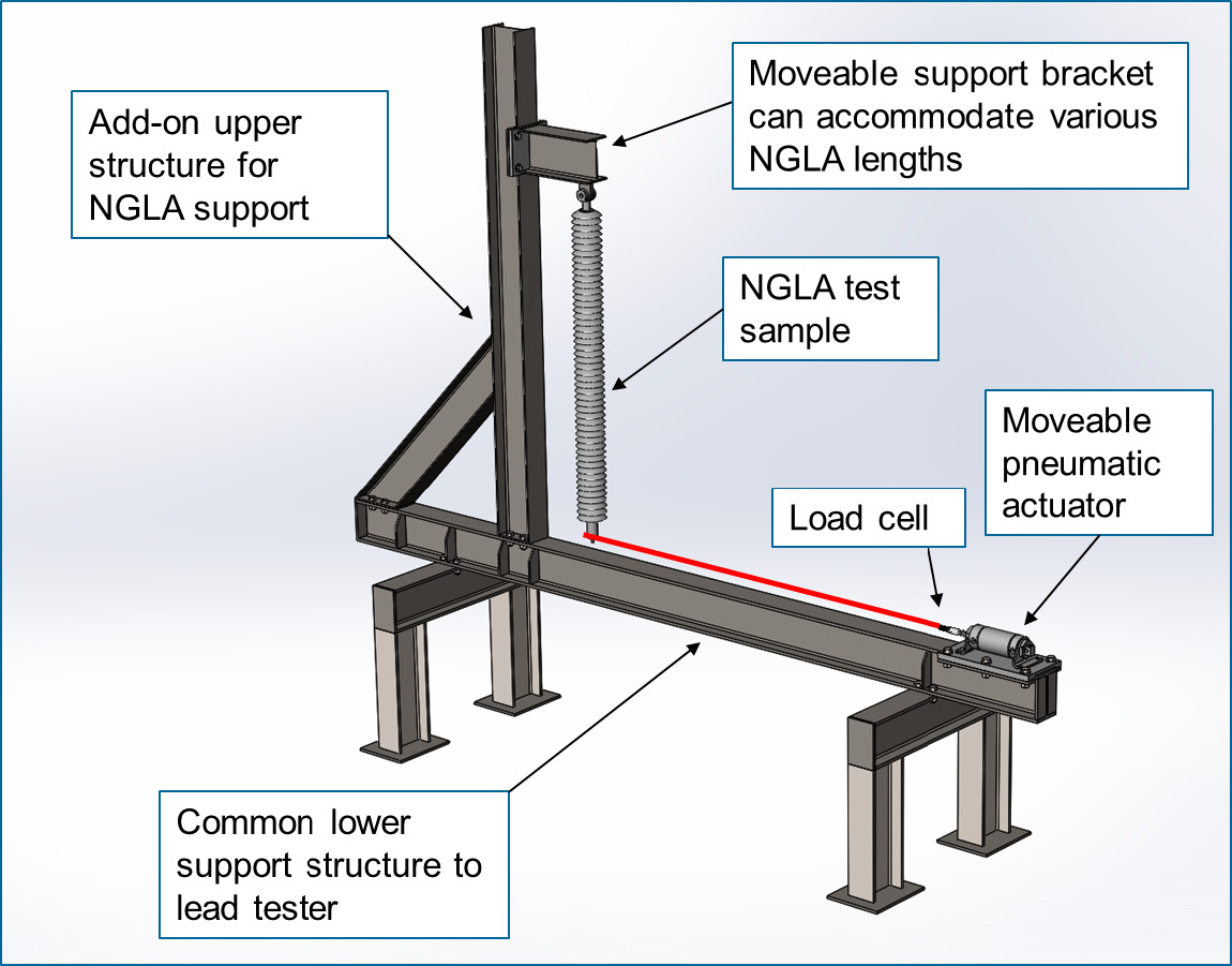
The intent of the test rig was to closely simulate the types of failures experienced by arrester leads in the field and to achieve this in an accelerated timeframe. Once a repeatable and realistic failure mode has been achieved, the device can then evaluate and compare different lead configurations and materials. Method of load application (i.e. actuator type and location) changed during the project based on types of physical degradation experienced by leads during the course of testing. For example, the initial lead loading method was using a pneumatic actuator, as seen in Fig. 4. However, it was discovered that the arrester’s relatively low inertia resulted in an unrealistically low load limit in the lead, no matter the size of actuator or pressure used.
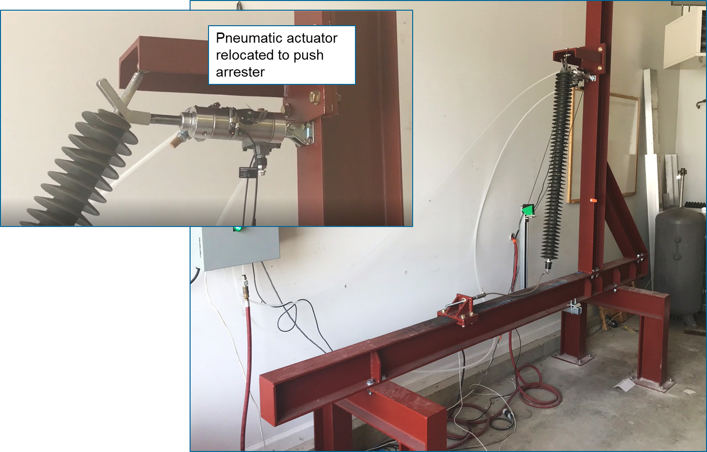

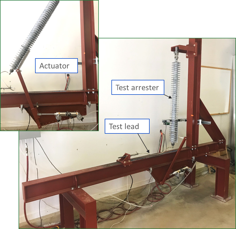
The next generation of load application method was by swinging the arrester to fixed angles, which when released resulted in desired loads in the leads (see Fig. 5). This more closely resembles how an arrester lead is actually loaded, i.e. via conductor and arrester wind motion, but required the top link of the arrester to be replaced with a simple pivot. The loads in leads were easily controllable with this method of actuation and the higher test loads required could be obtained. Nevertheless, this test configuration resulted in frequent failure of the arrester’s top attachment stud. Although such failures have been reported in the field, the high rate experienced during testing indicted that this loading method was not realistic. The final and still used generation of load application is via an underslung lever mechanism that contacts and pushes the bottom of the arrester (see Fig. 6). An advantage of this approach is that the arrester with its original top link assembly can be tested without modification.
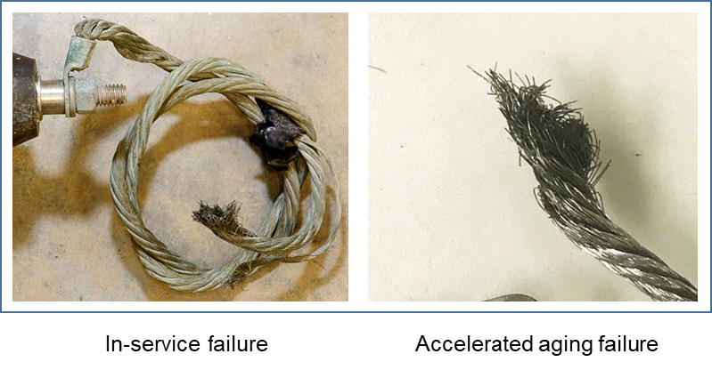
The leads of arresters tested using this rig configuration have exhibited closest comparison to types of failures actually experienced in service (see Fig. 7). Subsequent testing in the current rig will evaluate the effect on life expectancy of undesirable lead lug orientations (e.g. tightened so they are not in-line with the load) as well as different lead materials and configurations.
In addition to accelerated ageing of arrester leads, the impact of repetitive shock loading on arrester functionality will be monitored. A selection of arresters has been electrically tested prior to being used for lead ageing. After an equivalent 30 years of mechanical testing, these will be electrically tested once more to allow comparison.

Conclusions
Non-gapped line arresters are increasingly being applied to improve lightning performance of transmission lines. While these arresters perform well electrically, their installation is often compromised by failures of the connection leads or the disconnector. Service experience shows that many of these failures are due to installation related issues. For example, connections between arrester and energized conductor or grounded structure are often subjected to static and dynamic loads which could lead to fatigue or overloading, resulting in either broken connections or damage to the arrester. The fact that present test standards do not address requirements for arrester connecting leads prompted EPRI to develop a mechanical measurement and testing approach to better understand these issues. However, method of testing must be carefully selected so that failure modes most closely replicate those actually experienced in service. Even minor changes to test rig configuration can result in significant variations in types of failure observed.
References
1. Cigré WG 33.11 Task Force 03: “Application of metal oxide arrester to overhead lines”, Electra No. 186, October 1999, pp 83-112.
2. Williamson J., “Lightning Protection and Surge Arrester Application on NB Power Transmission Lines”, IEEE PES Transmission and Distribution Conference and Exposition, 2008.
3. Overhead Transmission Line Lightning and Grounding Reference Book 2011. EPRI, Palo Alto, CA: 2011. 1023429.
4. Application of Transmission Line Surge Arresters. EPRI, Palo Alto, CA: 2010. 1019954.
5. Guide for the Application of Transmission Line Surge Arresters. EPRI, Palo Alto, CA: 2009. 1017709.