This article, from a paper presented at a past INMR WORLD CONGRESS by R.A. Bernstorf, then Principal Engineer, Insulators at Hubbell Power Systems (now retired) offered an overview of key considerations when it comes to loading and application of braced line post assemblies.


Introduction
An insulator is a mechanical support. That is its primary reason for existence. Traditionally, transmission insulators were suspended from tower arms. Since those tower arms also serve as mechanical supports, a natural progression would be to use insulators to replace the structure arms. Initial efforts toward this end involved the use of line post insulators. The concept was attractive on several different fronts. The utilization of line posts as insulating structure arms reduced the overall size of the support towers. Additionally, by eliminating the traditional I-string, the design was able to more tightly fix the position of the conductors in space, reducing the required right-of-way width and assuring appropriate climbing clearances.
The early designs were manufactured with porcelain. Originally used for voltages 69 kV and below, the designs were expanded to accommodate higher voltages by increasing the length. As the section lengths (and applied voltages) increased, the line posts were required to support higher moments. Fortunately, the cross-sections (diameter) of the posts could be adjusted to achieve the appropriate cantilever strengths. Unfortunately, the weight of the assemblies increased as the square of the increased diameter.
Since the primary loading direction of concern was vertical, a triangular structural assembly was conceived that would address the shortfalls of the line post design. The line post and the existing support structure were used as two legs of the triangle. The third leg was created by adding an upward angled brace insulator from the line end of the line post to the tower to buttress the vertical strength and place the line post in a purely compressive loading situation. This was ideal for the porcelain line post, since porcelain is strongest in compression. Additionally, a universal joint was added at the ground end of the line post, converting it into a compressive strut. The universal joint removed the possibility of a cantilever load being applied to the compressive strut. A stub arm was added to the ground end of the angled brace insulator to impart an angle from the structure face to the pivoting hinge line of the design. This hinge angle offered resistance to longitudinal movement of the assembly under unbalanced conductor loading conditions by forcing the assembly to swing uphill. All end fitting connections for the strut were aligned along the axis of the post to minimize any applied moments. These concepts were originally developed by the Lapp Insulator Company and the line post with a brace was designated the “Horizontal-Vee”.

In the mid-1970s, Non-Ceramic Insulators (NCIs) were introduced. These insulators addressed a number of the concerns associated with porcelain Insulators. NCIs utilized the high tensile strength capabilities of unidirectional fiberglass rod. This contrasted with porcelain, which exhibits its best characteristics in compression. The high tensile strength of the fiberglass rod allowed the NCIs to have a relatively small core rod diameter while offering equivalent cantilever strength to porcelain. As a result, NCI line posts offered strength equivalent to porcelain at about a third the weight of the porcelain line posts. The NCI line posts offered an additional benefit resulting from their flexibility. Despite any advantages resulting from the substitution of NCIs for porcelain line posts and horizontal-vees, additional considerations are necessary regarding the loading of these assemblies.

Design Types
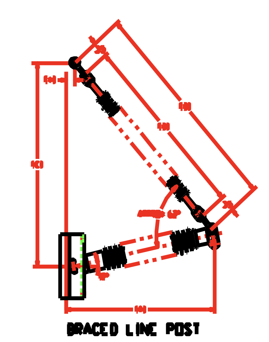
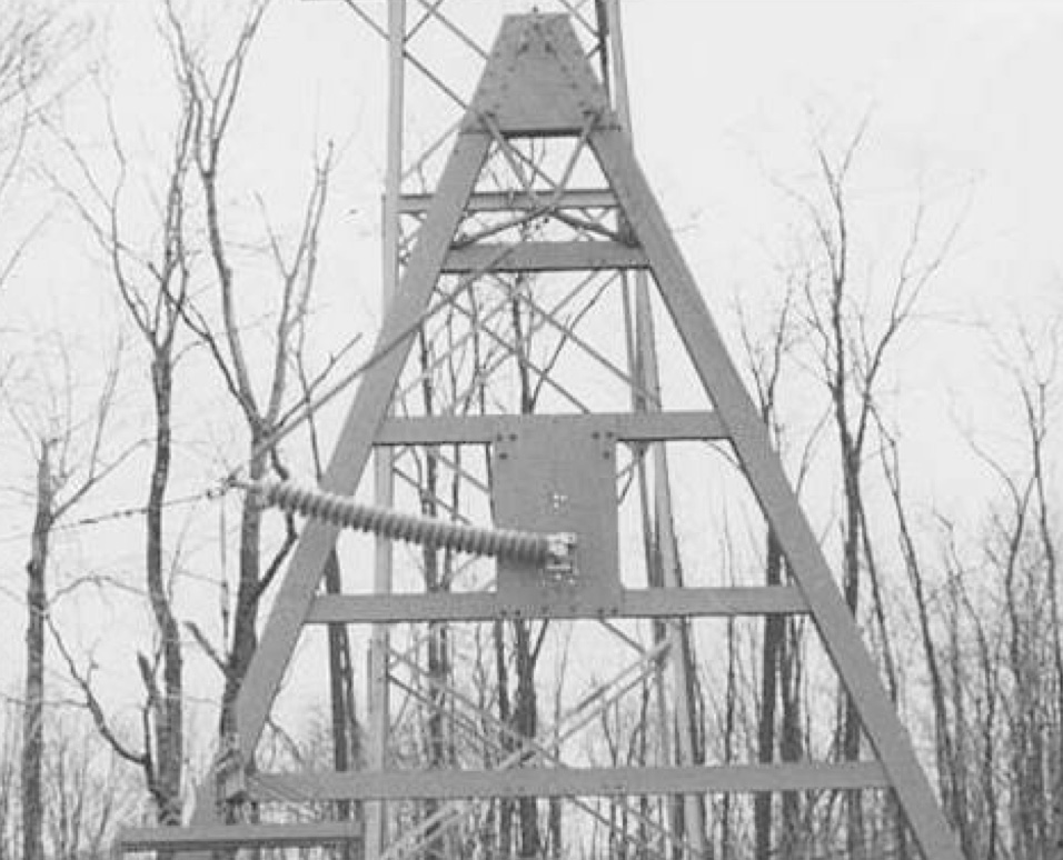
Substituting NCIs for the porcelain insulators in the horizontal-vee was relatively straightforward. The suspension insulator was a direct substitution. Replacing a ceramic strut with a NCI line post offered a few design opportunities. The flexibility of the NCIs made them more tolerant of longitudinal and eccentric loading. Traditionally, a universal joint would be used at the ground end of the strut insulator. But a vertically pinned connection (employing the flexibility of the strut insulator to swing in an upward arc) could also be employed to simplify the design. Taking the flexibility one step further, the design could employ a horizontal line post with a gain or flat base and no up sweep angle. Then the ground end stub arm from the suspension string could be eliminated. This design became the standard bearer for the product line and was designated the Braced Line Post (BLP). A typical design is depicted in Fig. 1. It utilizes the inherent cantilever strength of the line post member for longitudinal stability and simplifies the mounting by taking the brace suspension insulator string back to the face of the tower.
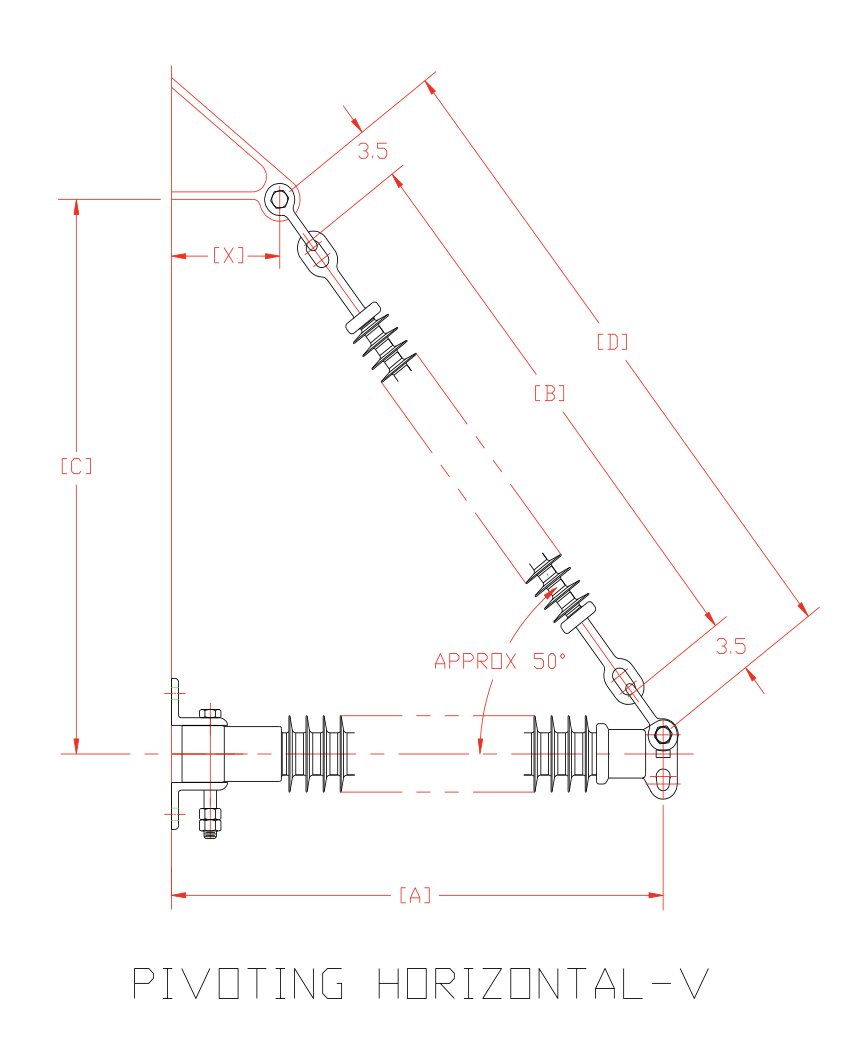
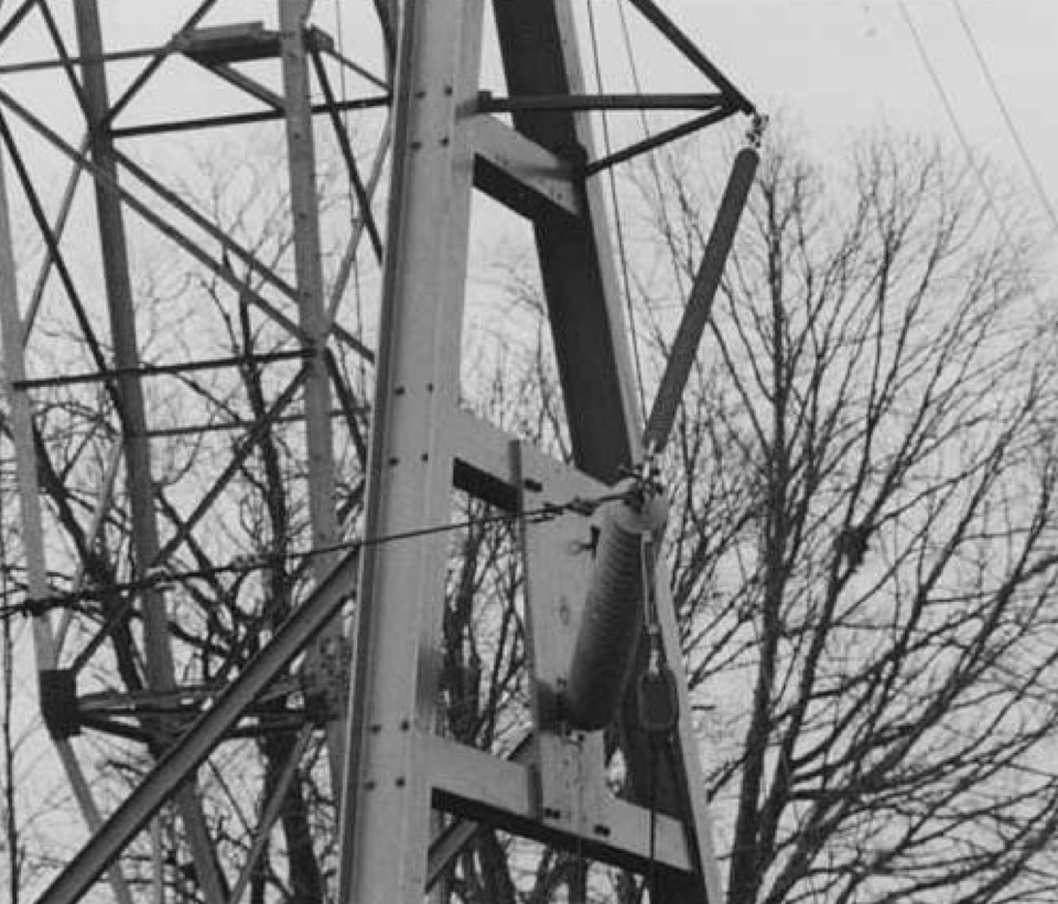
The “Horizontal-Vee” was designated the Pivoting Horizontal-V (PHV) to indicate the replacement of the universal joint with a vertical pivot pin. The stub arm at the ground end of the suspension insulator inclined the pivoting hinge line, imparting a degree of longitudinal stability that was dependent upon the vertical load being supported (see Fig. 2).
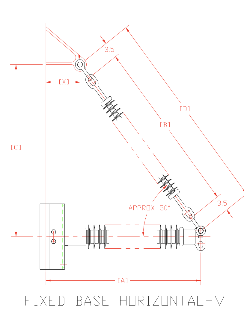
And the fixed based version of the PHV was designated the Fixed Base Horizontal-V (FBHV). The inclined hinge line’s longitudinal stability was buttressed by the cantilever strength of a fixed base line post member (see Fig. 3).
Mechanical Ratings
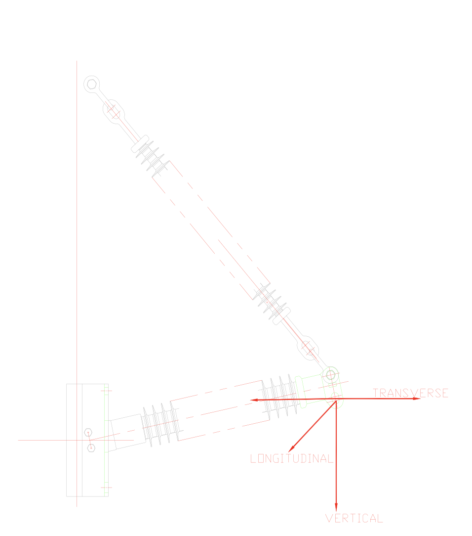
Load capabilities are typically assigned to a design as single load direction maxima. There are typically four of these (see Fig. 4):
Vertical (V)
Longitudinal (Lf)
Transverse Tension (TT)
Transverse Compression (TC)
The last two are separated because the line post may have different capabilities in these two directions.
Transverse Tension (TT)
Transverse Compression (TC)
The last two are separated because the line post may have different capabilities in these two directions.

Vertical Ratings
The largest mechanical advantage of a braced line post assembly is for vertical loading. It is important to define some of the basic parameters to be discussed as well as presenting a better description of the variations in the basic designs. Fig. 5 depicts an outline of the Braced Line Post assembly with the parameters of the design included. The application of those parameters will remain constant for all of the assemblies discussed.
Parameters
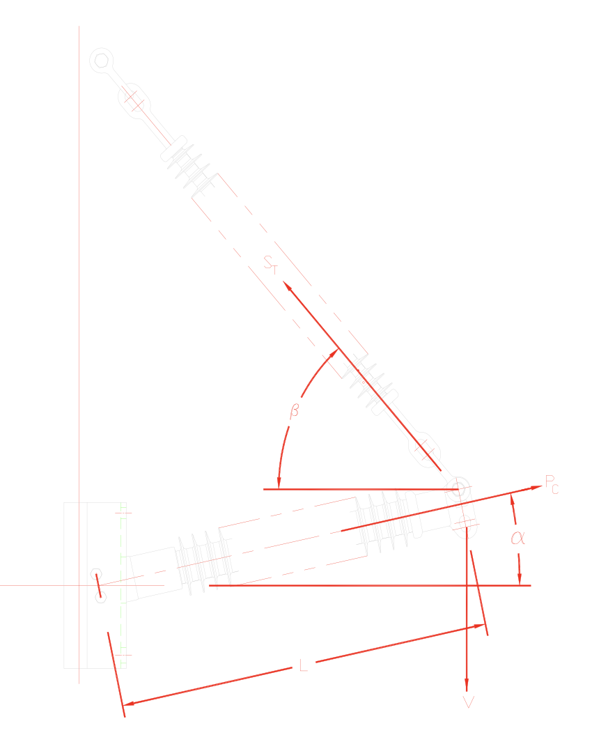
The free body diagram that appears as Fig. 5 includes all of the parameters associated with the design of the assembly. Those parameters are defined as follows:
Pc ≡ The compressive load applied to the post/strut member.
ST ≡ Tension load applied by the suspension brace insulator.
α ≡ Upsweep angle from horizontal of the post/strut member.
β ≡ Upsweep angle from horizontal of the brace insulator.
V ≡ Vertical loading applied to the line end of the assembly.
L ≡ Section length of the line post assembly
In the basic design of the braced line post and its ilk, consideration must be given to all of the components of the assembly with an eye toward the weakest component of the design, otherwise referred to as the weak link. The loads applied to the components are a function of the geometry. And the equations for those loads must consider the sum of the forces in the vertical and horizontal direction.
ΣFx = Pc*cos(α) – ST*cos(β) = 0 (1)
ΣFy = Pc*sin(α) + ST*sin(β) – V = 0 (2)
When designing a braced line post assembly, the strength of the suspension string is typically known. With that information, equations (1) and (2) become two equations with two unknowns and are easily solved. There is that one caveat to consider. The loadings cannot exceed the rating of the weakest link in any of the components of that suspension string. Assuming that all of the components of the brace suspension string have rated ultimate strengths equal to or exceeding that of the suspension insulator, the RTL of the suspension string would be ST. Then, a re-arrangement of equations 1 and 2 would yield the following:
V=ST*sin(β)+ (ST*cos(β)/cos(α))*sin(α) (3)
Equation (3) would seem to indicate that the vertical load capability of a braced line post is a function of the RTL (ST) of the brace suspension string.
But, equation (3) only considers one leg of the braced line post assembly. The weak link will still dictate the available strength of the assembly.
Knowing ST and V, the compression loading (Pc) on the line post member of the design can be calculated using equation (4).
Pc = (V-ST*sin(β))/sin(α) (4)
However, calculating Pc does not guarantee that the line post is not the weak link. Oftentimes, the holes in the blade of the line end hardware become a limiting factor. Or, the length of the line post can impose limits in the form of elastic buckling (see Fig. 6 and 7).
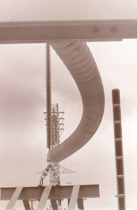
As noted in the introduction, NCIs were originally developed to utilize the high tensile strength capabilities of unidirectional fiberglass rod. As a result, NCIs have relatively small core rod diameters. This makes them more susceptible to elastic buckling when subjected to large compressive loadings, which can result from the application of a vertical load.
This is, in part, a function of the slenderness ratio (L/r) for the core rod used in the line post design. While elastic buckling may not be an issue for a relatively short line post, it may limit the loadings available for designs intended for voltages above 230 kV.
The Euler’s buckling equations apply to the buckling situation as shown below:
Buckling Load = (π2*E*I)/(K*L)2 (5)
Where,
E = Young’s Modulus
I = Moment of inertia
L = Section length of line post
K = End Conditions of line post
All of the parameters shown are known, except for K. In classical theory, K represents the effective buckling length of the column being loaded and is a function of the end conditions for that column. K can range from 2 for a fixed/free column, to ½ for a fixed/fixed column. So the problem became how to define K2 for the braced line post application.
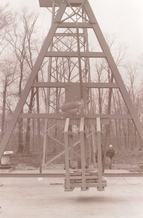
The most direct way to find K2 was empirically. As a result, a series of full scale tests were performed on braced line posts, pivoting horizontal-Vs and fixed base horizontal-Vs. After careful consideration of loading methods, a free-weight method was employed to simulate vertical loading and avoid any bias that might result from fixed point loading.
Techniques had to be developed to determine the onset of elastic buckling. Subjective judgments proved inconsistent. And because of the discrete loadings employed with free weights, the onset of buckling was often bracketed. As testing methods improved, it was found that most of the elastic buckling occurred in the horizontal plane with the line end fitting of the line post exhibiting longitudinal movement. The position of the top cap was measured from a longitudinal reference point to track deflection (see Fig. 8).
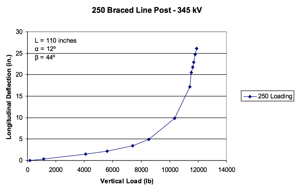
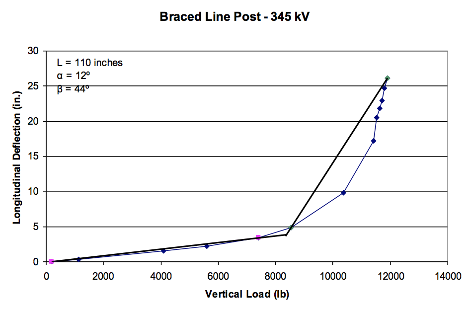
Trend lines could then be inserted in an attempt to identify the onset of elastic buckling. The data collected below the onset of buckling was linear. But the non-linear nature of the data above the elastic buckling onset introduced some uncertainty regarding the exact onset (see Fig. 9).
While vertical loads were applied directly, the data was converted using a recombination of equations (1) and (2) to determine the compression on the line post directly.
V =( Pc*cos(α)/ cos(β)) *sin(β)+Pc*sin(α) (7)
Or,
V = Pc*(cos(α)*tan(β)+ sin(α)) (8)
So,
Pc = V/((cos(α)*tan(β)+ sin(α))) (9)
A variety of designs were evaluated for the onset of elastic buckling using this technique. Fig. 10 depicts the data collected in this manner. Each of the data points has an associated error bar for the reasons stated above.
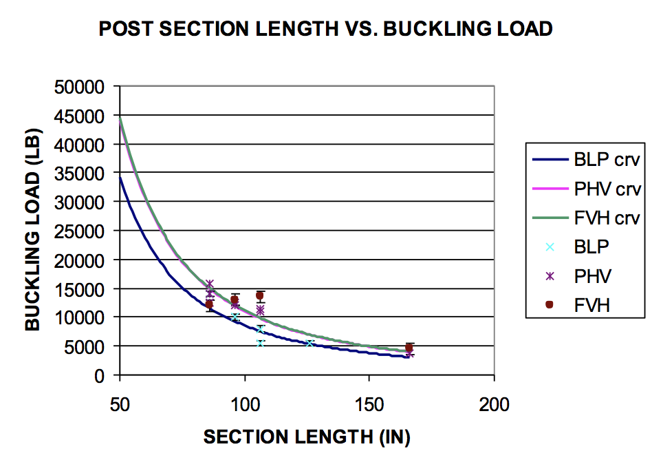
In hindsight, the horizontal buckling phenomenon made sense since the typical application used some form of blade on the line end of the post with two separate attachment points. The upper hole was used to attach the suspension insulator brace. The lower hole was used for the application of the vertical load. The loading between these two holes approximates a central loading problem. Any vertical buckling by the line post would shift the position of these holes, applying a restoring moment to the line end. In essence, a degree of fixation in the vertical plane had inadvertently been applied to the line post.
The data collected was fitted to Euler’s equation as represented in equation (6).
Buckling Load = (π2*E*I)/(K2*L2) (6)
The curves fitted to the data represented buckling equations as noted below:
Braced Line Post:
Buckling Load = (π2*E*I)/(1.33*L2)
Pivoting Horizontal-V:
Buckling Load = (π2*E*I)/(1.03*L2)
Fixed Base Horizontal-V:
Buckling Load = (π2*E*I)/(1.02*L2)
The onset of elastic buckling represents the initiation of instability. The line posts can typically sustain much higher loads without failing. As a guide for application, the maximum compressive load applied to the line post should never exceed 80% of the calculated elastic buckling load.

Application Curves
The vertical load capability of an assembly is worth knowing. But in the real world, combinations of loading are more likely to occur. The flexibility of the NCIs makes careful consideration of these combinations essential. For example, if a significant longitudinal load exists, the line post member of a braced line post or a fixed base horizontal-V might deflect in accordance with the following equation.
Δ = Lf*L3/(3*E*I)
Where,
Δ ≡ deflection (inches)
Lf ≡ applied Longitudinal load (lbs)
E ≡ Young’s Modulus ≈ 6,000,000 (lb/in2)
I ≡ Moment of inertia
L ≡ Section length of the line post (in.)
If the deflection is significant, then any compressive force applied to the line end of the post member adds to the moment being applied as below:
Added moment = Δ*Pc
Transverse compression loads would also contribute to the moment applied to the ground end of the post strut member as a function of the deflection, Δ.
Of course, if moments due to longitudinal loading are to be avoided, a pivoting horizontal-V can be employed. In these designs, longitudinal deflection becomes a function of the vertical load, and the deflection can be substantial (see graphics X and Z).
But the real work that takes place in generating a combined loading curve goes a little deeper than that. A combined loading curve must at least consider the following factors:
• Tension in the loading of the brace insulator string.
• Compression loading of the line post insulator
• Load magnitude to the line end fitting
And, in addition, for the braced line post and fixed base horizontal-V:
• Total applied moment to the line post insulator
Most curves appear as a series of contour curves representing various longitudinal loads applied to the assembly. The abscissa is the transverse load applied to the assembly, representing both the compressive and tensile loadings. And the ordinate indicates the remaining vertical capability of the assembly.
In calculating the vertical loading capability, each of the above listed items must be considered to assure that the weakest component is not overloaded. Then the lowest resulting load becomes the rated vertical capability of the assembly.
To employ the application curve, first choose an appropriate longitudinal load for the assembly and find that curve. Then find the transverse load that the assembly must withstand on the abscissa, and read the vertical load from the ordinate. As long as the displayed vertical load is greater than or equal to the planned maximum vertical load, the assembly will be operating within its working range.

Conclusions
A braced line post, pivoting horizontal-V or fixed base horizontal-V will offer significant performance improvements over a standard line post. However, there are limitations to the capability of the assembly, the foremost being elastic buckling of the line post subassembly. As long as loadings are kept within the recommendations of the appropriate application curve, mechanical issues do not arise and the improvements in mechanical strength associated with these designs can be employed.
References
[1] R. A. Bernstorf. “Fiberglass Structural Members Utilized in the Horizontal Vee and Similar Structures”, The Ohio Brass Company, Wadsworth, Ohio.
[2] R. A. Bernstorf. “Braced Line Post Ratings”. Presented at the 2008 IEEE-PES Transmission and Distribution Conference and Exposition, Chicago, IL, April 21-24, IEEE Paper Number PESGM2006-000680.