The National Electrical Safety Code (NESC, IEEE C2-2012) specifies horizontal and vertical clearances of unguarded parts and clearance between guard to live parts on EHV power systems (345 kV and higher). Basic clearances are specified, which can then be adjusted based on switching surge factors.
This edited past contribution to INMR by engineers at Salt River Project reviewed switching surge overvoltage studies performed for several 500 kV lines in their system. In cases where line clearances were found inadequate to meet NESC criteria, switching surge factors were reduced by installing 500 kV line arresters at selected locations. The experience proved that installation of transmission line arresters can be an economical approach to reduce switching surge overvoltages at selected line locations.


Switching surge factor (SSF) is defined as the ratio of maximum switching surge voltage to maximum operating crest voltage (line to neutral) of a power system. It is also stated that switching surge factor is a design factor that determines selected clearances. Moreover, NESC specifies that adequate data to support these design factors has to be available. As example:
For a 500 kV system, Maximum crest operating voltage (line to neutral) = (550/sqrt (3))* sqrt (2) = 449.1 kV. If the switching surge (line to ground) voltage is 808 kV, switching surge factor = 808/449.1 = 1.8 pu.
Table 124.1 of the NESC (IEEE C2-2012), gave clearances for switching surge factors ranging from 1.8 to 2.7 pu for 500 kV power systems.

Switching Surge Voltages
Switching overvoltages occur because the voltages at the instant of switching in a power system are not the same as final voltages. When a breaker is closed, there will be transition period during which the voltages may overshoot by as much as to levels over 300 percent. Front time of the initial transient can be from a few hundred microseconds to one to two milliseconds. EHV line energization and/or reclosing overvoltages have significant impact on design of a line and of the equipment at terminal stations.
Line switching overvoltage levels along the length of a transmission line are statistical in nature and depend on factors such as the instant of breaker closing on the voltage wave, relative closing times of the various poles, transmission line length, parallel lines in the same right of way, ground path characteristics, etc. When a transmission line is switched open, (trapped) charges remain on the line and slowly decay to zero. Overvoltage levels are normally higher for ‘reclosing’ a line with the trapped charge compared to line ‘energization’ without the trapped charge. Line design is usually based to withstand 98% value.
Line energization is not the only cause of switching surge overvoltages on transmission lines. Other causes include:
• Switching shunt capacitor banks;
• Switching series capacitor banks;
• Switching shunt reactors;
• Fault occurrence and fault clearing;
• Other switching operations.
Study of Transmission Line Energization Overvoltages
Transmission line energization overvoltages cannot easily be calculated by analytical equations. Before computers, these were calculated by Transient Network Analyzers (TNAs). In a TNA study, the power system is physically modeled on a smaller scale. Transmission lines are modeled as distributed inductors and capacitors while generators are modeled as equivalent sources. The breaker, usually modeled by a computer-controlled switch, is repeatedly closed hundreds of times and results are statistically analyzed to compute maximum overvoltages.

Description of EMTP Studies
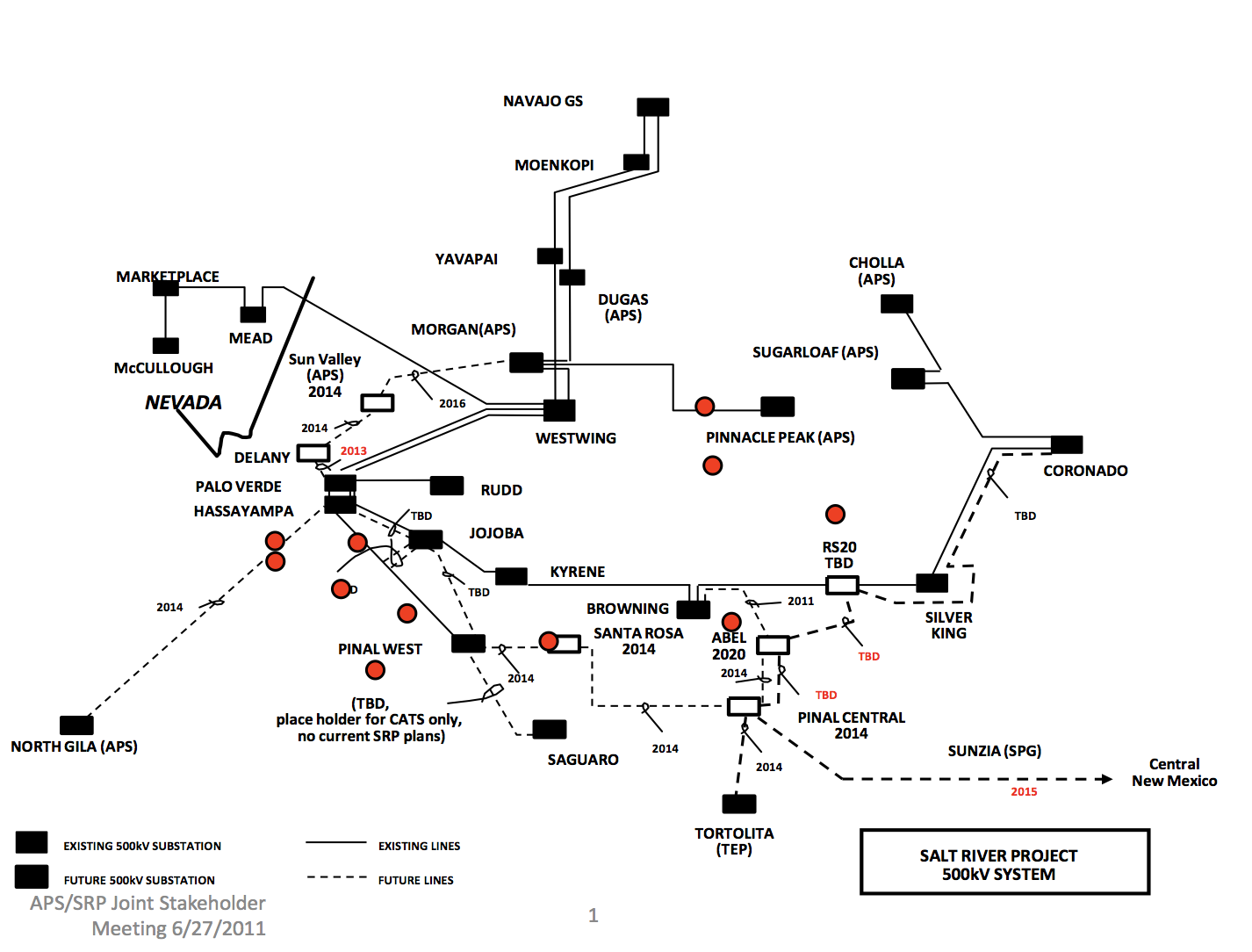
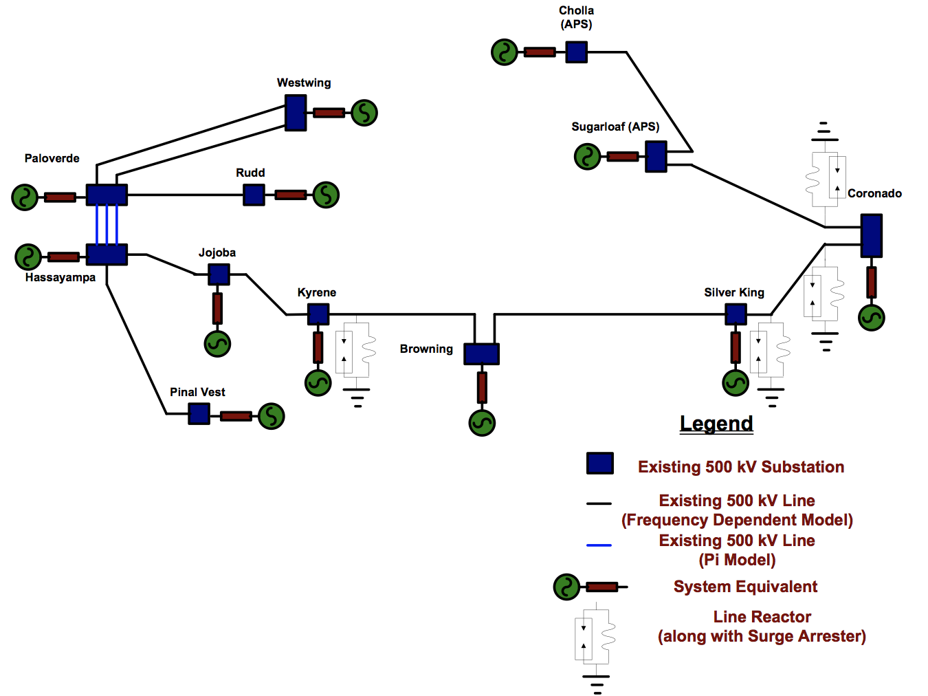
TNA studies are now obsolete – replaced by digital computer programs such as Electromagnetic Transient Type Programs (ATP, EMTP, PSCAD/EMTDC. etc.). Fig. 1 shows an overall view of the Salt River Project (SRP) and the adjacent 500 kV transmission system. In order to calculate the switching surge factor for SRP transmission lines, the system bounded by the substations represented in red are modeled, using the PSCAD/EMTDC program. Fig. 2 is a more detailed representation of the boundary substations along with the lines of interest. The system equivalents at the boundary locations are calculated using a short circuit data base. The calculated system equivalent parameters include positive, negative and zero sequence impedances at each boundary bus and between all boundary buses. Lines of interest, where switching surge factors are calculated, are represented by the frequency dependent (phase) model. This line model is a distributed RLC traveling wave model that incorporates frequency dependence of all parameters. The lines not subject to detailed analysis are modeled as coupled Pi-Line sections.
Line Arrester Model
396 kV or 420 kV rated line arresters are utilized at various locations along the line to limit voltages within the acceptable limits. Preference is given to 420 kV rated line arresters.
Series Capacitors at Coronado-Silver King Line Terminals
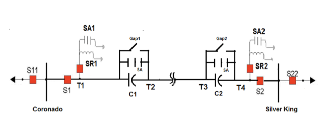
Series capacitor installations at the Coronado-Silver King Line terminals were modeled in detail. Gaps across the series capacitors were modeled to short out the series capacitors for specified MOV current and energy settings (see Fig. 3).
Study Results
Line clearances for all 500 kV lines were measured using Light Detection and Ranging (LiDAR) technology. An SRP contractor provided this service, in which an aircraft-mounted remote sensing module is used along the power line corridor. Relative distances are measured by illuminating the objects in the corridor with a laser and analyzing reflected light. A 3-D point cloud is interpreted to create a model of the transmission line, topology of terrain, vegetation and structures in the right-of-way. Once the points are classified and the model created, transmission design software can be used to evaluate various scenarios, such as the conductors carrying rated current and heated to maximum operating temperature or conductors displaced laterally by wind of specified force per square foot. The transmission design program then produces a summary of any clearance concerns from the energized wires to ground, to power lines that cross the corridor, buildings, signs, poles, bridges and so on.
The NESC requires that adjustments be made for local conditions such as elevation above mean sea level. It also allows for reduced clearance to ground in a ‘pedestrian only’ area not traversed by large vehicles or riders on horseback. For higher line voltages (generally applicable at 230 kV AC and above), if an engineering study has determined that switching surge factors are lower than default values, certain clearance requirements can be reduced.
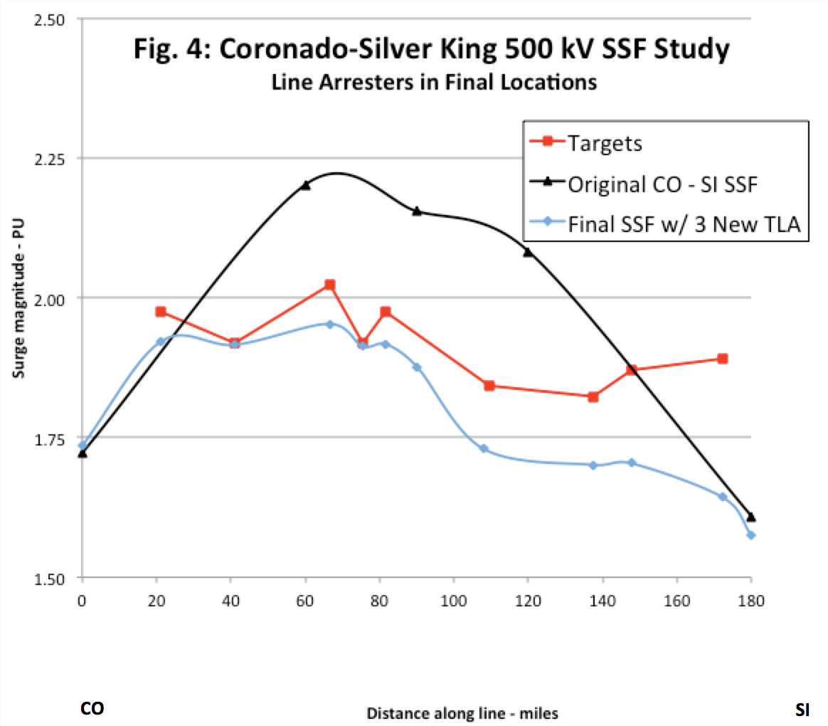
Switching surge overvoltages were computed for all 500 kV lines shown in Fig. 2. Detailed results are shown here for Coronado-Silver King 500 kV Line, which is 180 miles long and transmits power from Coronado (CO) generating station to Silver King (SI) receiving station. Springerville generating station is connected to Coronado by a 50-mile tie line. Hence, the CO-SI Line plays an important role in transmitting the power generated to metro Phoenix.
Results of switching (reclosing) surge overvoltages for the CO-SI Line are presented in Figs. 4 and 5. The reclosing operations from Coronado are in 60 cycles and from Silver King are in 35 cycles from the line opening times. As explained, switching surge overvoltages are statistical in nature and values shown are 2% values. When the line is switched 100 times, voltages exceed the stated values in 2% of the cases. In these figures, switching surge factors are computed on 550 kV (1 per unit) base values. Original study values were converted from 525 kV base to compare with NESC numbers. In Figs. 4 and 5, target values are based on measured line clearances and the switching surge factor on NESC specifications. The CO-SI 500 kV Line has arresters installed at Coronado and Silver King stations to limit switching overvoltages at line ends. With arresters at line ends only, switching overvoltages exceed target values at several locations along the line. The solution adopted was to install 420 kV rated transmission line arresters (TLAs) at three locations: 60, 108 and 137 miles from Coronado. A study confirmed that installing arresters at these points would limit overvoltages to meet NESC criteria.
Some iterative fine-tuning was required to select TLA locations that met the criteria. As shown on Fig. 5, in Case 9c, the SSF still exceeded at mile 41 along the line. The adjustment in Case 9d improved the result here, but meant a small excess SSF at mile 66. In Case 9e, the targets are satisfied at all critical locations.
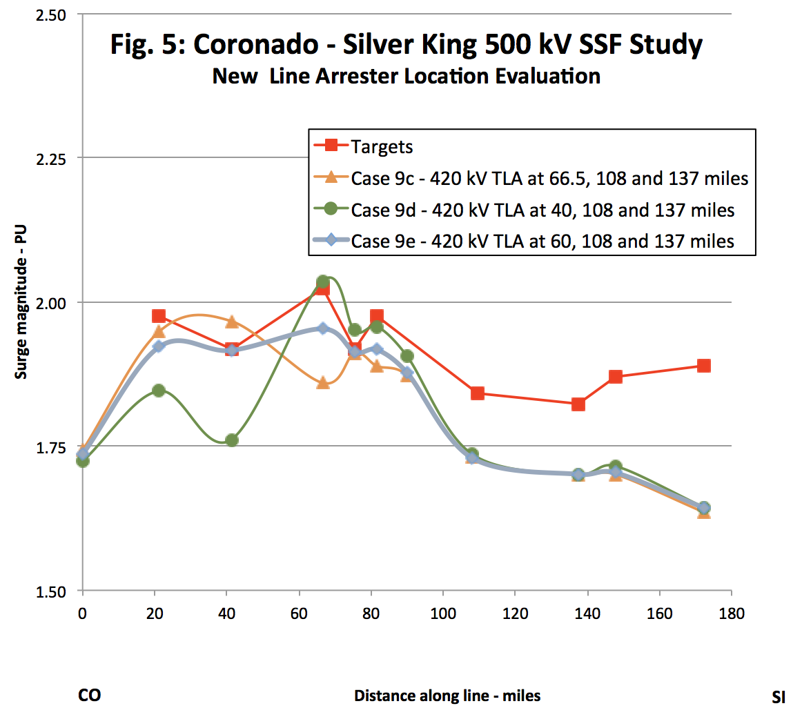
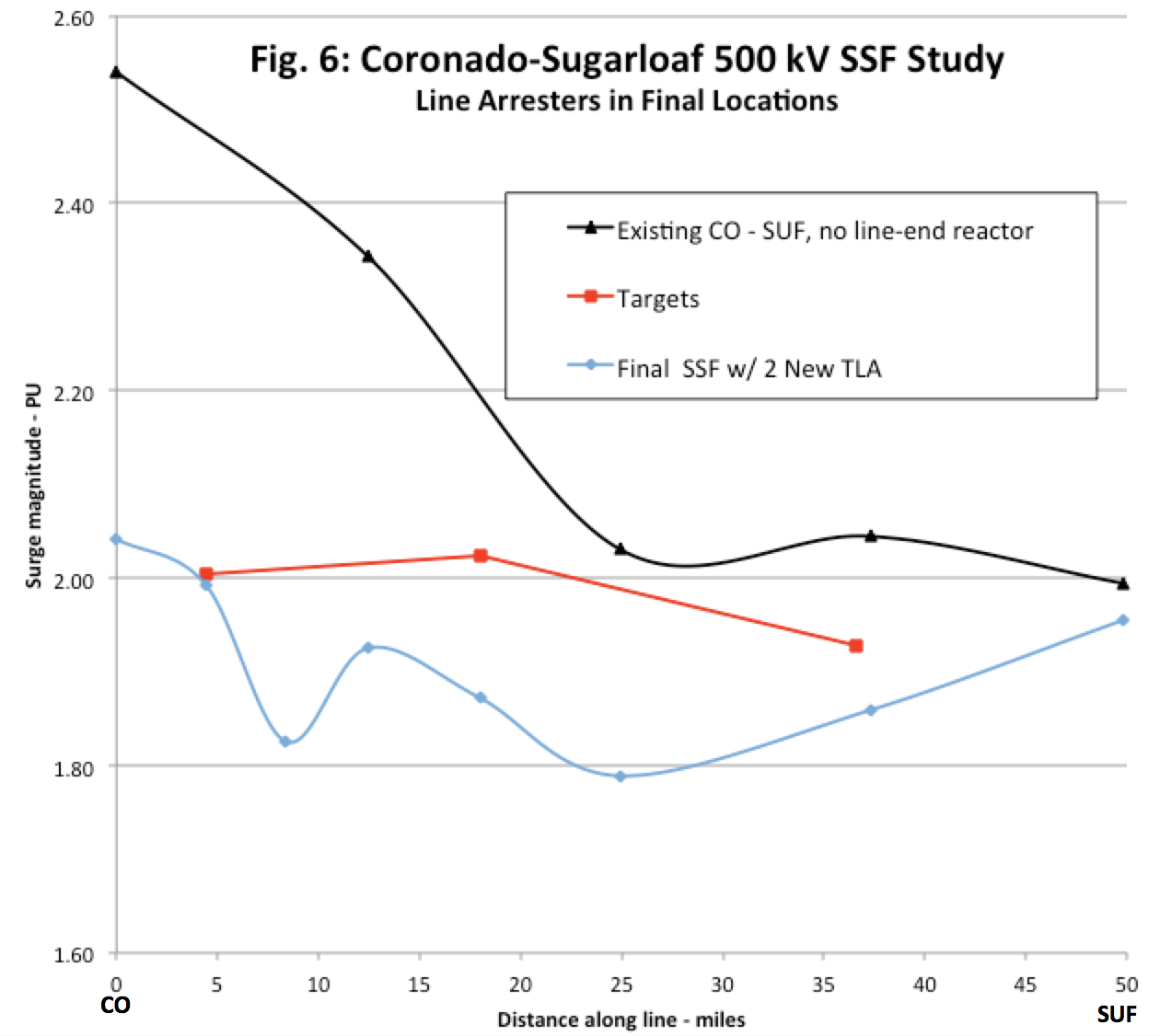
In another sensitivity case, it was shown that all of the Coronado-Silver King criteria would be met with the same TLA locations as Case 9c if the TLAs were rated 396 kV rather than 420 kV. Installing the lower protective level arresters would have reduced the SSF at mile 41 by 0.10 pu. As indicated earlier, SRP prefers the 420 kV rating because the arresters are less likely to be hit by voltage surges that will cause the metal oxide varistor blocks to conduct, which results in a less demanding duty cycle. SSF study results for another SRP transmission line, Coronado-Sugarloaf, are shown in Fig. 6. For this line, the switchings (energizations) are conducted long after opening, without trapped charges. In the pre-TLA case, the SSF calculated at Coronado was pessimistic because of the assumption that an existing line-end reactor, which is protected by arresters, might be switched off. It was found that two TLAs were sufficient to meet target SSF levels for this line, if located at 9 and 25 miles from Coronado.
 Selection of Transmission Line Arresters
Until recently, preferred methods for limiting switching overvoltages on transmission lines included:
1. Installing breakers with pre-insertion resistors;
2. Synchronous switching of breaker poles.
Breaker switching modification, as above, is considered to reduce breaker reliability. Switching surge voltage reduction is along the entire line and not at a specific location. Arresters can be installed on transmission lines to reduce lightning or switching overvoltages on the lines. There are two types of Transmission Line Arresters: Externally Gapped Line Arresters (EGLAs) and Non-Gapped Line Arresters (NGLAs).
Pros and Cons of EGLAs & NGLAs
Externally Gapped Line Arresters
Pros:
No disconnectors needed.
Arrester not stressed with continuous voltage and hence there is freedom to design the arrester voltage.
Cons:
Insulation coordination not precise and difficult because gap sparkover not precise;
No control of switching overvoltages;
Arrester has to be individually designed for each situation – tower, conductor location;
Difficult to identify failed arrester.
Non-Gapped Line Arresters
Pros:
Precise insulation coordination;
Flexible design for installation – tower, conductor etc.;
Easier to identify failed arresters.
Cons:
Disconnector needed and complicated for high voltage arresters;
Arresters stressed continuously and hence higher rated voltage needed than for EGLAs.
Salt River Project (SRP) selected gapless metal oxide arresters housed in polymeric housings for installation on selected 500 kV lines at strategic locations, based on extensive switching overvoltage studies. Since line insulation after failure is self-restoring, the line arresters are provided with disconnectors. This facilitates the line being energized immediately in the event of arrester failure without replacing it. Operation of the disconnector makes it easier to identify any failed arrester.

Arrester Specification
Line energization for switching surge calculation showed that the energy discharged in the line arrester was not significant for a standard station class arrester. However, line energization is only one of many situations that will stress the line arrester and therefore these arresters are conservatively specified with the same energy rating as for a typical station class arrester. SRP specified 420 kV duty cycle rating arresters for its 500 kV system and has had good operating experience. Considering the high reliability required for line arresters, they are specified with 420 kV duty cycle rating. Highlights of TLA specification are as follows:
Maximum Continuous Operating Voltage (MCOV) kVrms 335
Duty Cycle Rated Voltage, kVrms 420
ARRESTER ENERGY RATING
Energy Handling Capability*: 13.0 kJ/kV of MCOV
(*as described in IEEE C62.11, Draft 9, November 2011, Energy class G)
Vendor shall provide type test data as proof that the arrester meets the energy handling capability specified above.

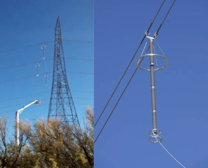
Installation
A crane with an insulated boom, known as a Condor, was used due to the height of the wires. Attachment hardware was simple and consisted of readily available standard items. SRP elected to use armor rod rather than clamping directly to the aluminum outer strands of the conductor. The device lends itself to ‘hot’ installation. Performing work with the line energized simplified the process greatly, since 500 kV line outages are challenging to arrange. At one location, arrester condition monitors were installed, mounted on the lattice tower in series with the ground lead. Files can be downloaded via a wireless USB communications device and this will provide intelligence regarding arrester functionality as well as the number of surges seen by each arrester.
Conclusions
Switching surge overvoltages can be reduced by installing transmission line arresters (TLAs) along a line. Gapless metal oxide arresters in polymeric housings are preferable over externally gapped line arresters (EGLAs) for this application since they provide more precise insulation coordination and flexible installation. Switching overvoltage studies, using EMTP type programs, provide information to select the locations along the line that provide for the required switching surge reduction where line clearances are critical. Standard station class arrester energy rating specification is recommended for TLAs.