Transmission line surge arresters (TLSAs) are applied on overhead lines to improve outage performance and in the case of EHV also to limit magnitude of switching overvoltages. There are two basic types: externally gapped line arresters (EGLAs) and nongapped line arresters (NGLAs). In some countries, such as the United States, transmission line arresters are mostly NGLA type. Fabio Bologna and Chris Engelbrecht of the Electric Power Research Institute (EPRI) summarize findings of a project that covered several years and whose goal was to understand causes of lead breakages on NGLAs. This will allow users to better formulate functional requirements to be included in the technical specifications they issue.

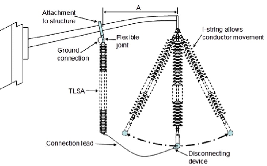
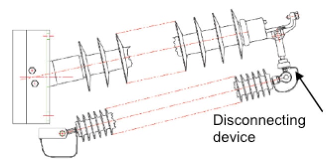
NGLAs are comprised of a column of metal oxide varistors (MOVs), reinforced by fiberglass straps or loops and packaged in a polymeric housing. These arresters are installed between phase conductor and tower employing connection leads. One end of the arrester is typically fitted with a disconnector to break the connection in the event of failure. Installation configurations can be classified into one of three broad groups:
• Mounted onto tower or hung from cross-arm;
• Hung from conductor;
• Installed parallel to line insulator as part of insulator assembly.
Service experience has demonstrated that, from an electrical standpoint, application of NGLAs often improves line performance with relatively few failures. At the same time, however, utilities report that NGLA installations can sometimes be compromised by mechanical issues, such as failure of the connection lead or disconnector. This has been identified as a possible design weakness and is a topic that warrants careful consideration.
Typical Installation Problems with NGLA Applications
EPRI actively collects service experience from member utilities and manages a database of failure reports from line inspections. A summary of typical installation problems found during such inspections is then provided for each different installation configuration.
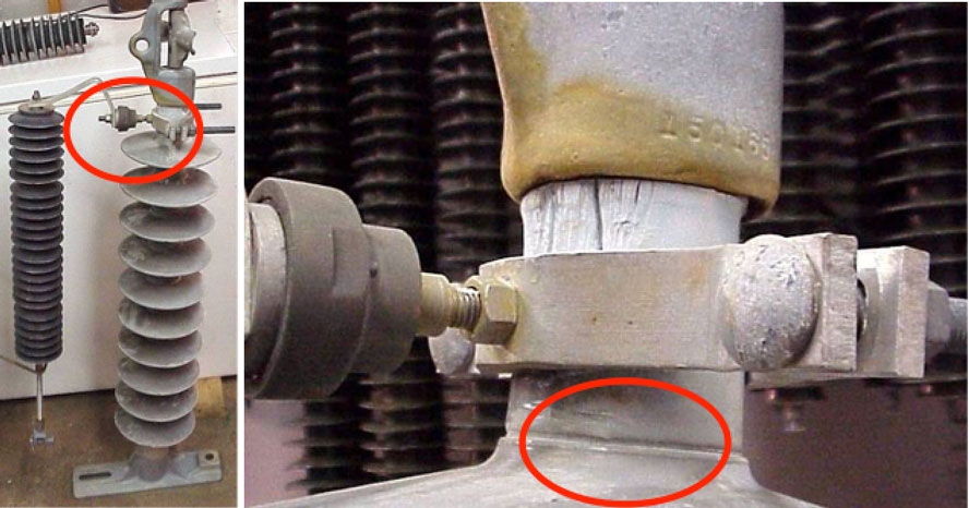
1. Mounted onto tower or hung from cross-arm
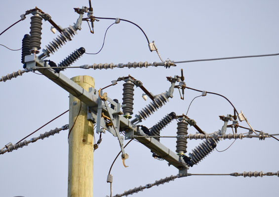
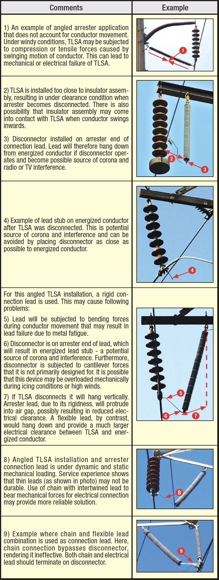
A popular method for installing an NGLA is to hang it from the cross-arm of the line structure or to mount it on the structure with a lead connecting the live side of the arrester to the phase conductor. An overview of a typical such installation is shown in Fig. 1. Examples of common installation errors observed during line inspections are given in Table 1.
CLICK TO ENLARGE
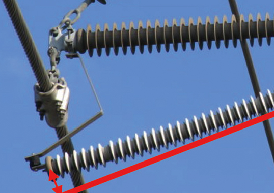
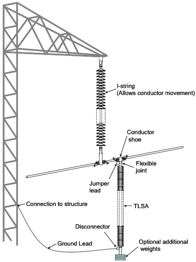
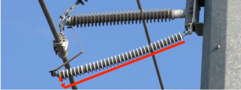
2. Hung from Phase Conductor
NGLAs can also be applied on phase conductors, with the connection lead between the base of the arrester and the grounded support structure. An example of a typical such installation is shown in Fig. 2.
CLICK TO ENLARGE
In recent publications, expert, William Chisholm, pointed out that several mechanical interactions need to be considered when installing arresters directly onto phase conductors. These include: (1) pendulum frequencies to avoid mechanical resonance; (2) effect on performance of vibration dampers due to arrester weight on conductor; and, (3) introduction of vibration tests for clamps used to mount arresters.

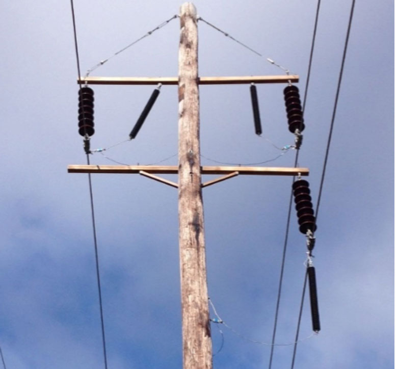
3. Installed Parallel to Line Insulator as Part of Insulator Assembly
A number of arrester manufacturers offer options for installing a surge arrester in parallel to the insulator as part of the insulator assembly. Here, the arrester is attached with short connections to the insulator’s end fittings or associated hardware, as shown in Fig. 3.
CLICK TO ENLARGE
This type of installation requires substantial pre-engineering due to the proximity of the TLSA to the insulator. Consequently, relatively few problems are experienced if installed correctly. A weakness of this installation design, however, is that the attachment method and connections need to be optimized for each different type of insulator assembly (i.e. model, length, type of end fitting, etc.). There is therefore a risk that some arresters could end up being installed on incompatible insulators assemblies, resulting in either loose-fitting arresters or arresters attached to inappropriate parts of the insulator. This could result in damage to the arrester and/or insulator.
CLICK TO ENLARGE
Another potential problem occurs when surge arresters are installed in a horizontal orientation or at an angle to vertical. In such cases, the weight of the arresters (especially for long units) can be significant and has to be considered. Depending on length, bowing could occur along the unit.
CLICK TO ENLARGE
Testing Connection Leads
Based on the service experience discussed above, it is clear that many of the failures observed in service are caused by broken connection leads. TLSA installations should therefore be designed to minimize mechanical stress on the connection lead and disconnector since these components – especially the disconnector – are unable to tolerate high mechanical loads. Other mechanical design considerations include:
• Connections should allow free movement of phase conductors, which could take the form of conductor swing, aeolian vibrations, galloping and sub-span oscillations;
• Connections and associated hardware should withstand all mechanical forces they are subjected to;
• Connections should be durable so as to withstand fatigue due to movement;
• Installation and connections should not place excessive mechanical loading on the arrester or disconnector attachments;
• Disconnection of the arrester should occur in a controlled manner, without consequential damage to it or other equipment.

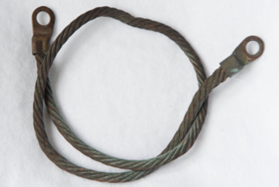
Connection Leads
Lead wires are used to connect arrester units either to the phase conductor or to a grounded part of the line support structure. There are generally two types of lead configurations:
CLICK TO ENLARGE
1. Flexible rope type wires with crimped lug connectors are used in applications where the lead is not subjected to high mechanical loads;
2. Chain intertwined with the lead wire has been used with success in cases where significant mechanical loads are expected.
Since the primary function of the leads are to establish an electrical connection, they should be designed to carry (1) low magnitudes of continuous current flowing through the arrester during normal operation; (2) high impulse discharge currents when the arrester conducts a surge; and (3) power frequency fault current should the arrester fail. The lead also implicitly establishes a mechanical connection and therefore it is necessary to consider such forces when designing the lead attachment.
Two types of leads are typically used on NGLA applications and their function is slightly different. One should be able to isolate the arrester should it fail. This lead typically comprises a flexible lead in series with the disconnector, which is designed to operate when the arrester fails. The other connection is typically much shorter and serves to electrically bypass mechanical joints that can have a high electrical contact resistance and cause sparking. These bridging leads also protect the mechanical support from damage due to high discharge or fault currents.

Observed TLSA Connection Lead Failures
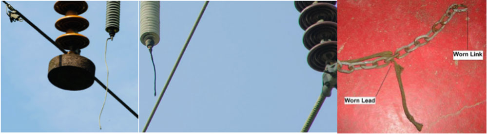
Examples of common lead failures include:
• The lead wire pulling out of the lug. This is a common problem possibly the result of a mechanical overload or poor crimping of the lead connection;
• The edge of the crimped lug ‘sawing’ into the lead conductor, severing strands and weakening the lead mechanically. This can occur when a mechanically loaded lead is not well aligned with the lug;
• Wearing down of the lead in chain connections (where it is woven through the chain) due to continual movement.
CLICK TO ENLARGE
Testing Performed
EPRI developed a simulated field test to quantify typical in-service mechanical lead loads under different environmental conditions. The test measures mechanical loading of the arrester as well as leads under real-world conditions and any degradation of components is recorded. It is hoped that this information will provide for a better understanding of lead loads and also a technical basis for future laboratory testing. Instrumenting an energized installation was not considered cost-effective since only the mechanical forces in the lead are of interest. In January 2015, three typical arrester configurations were installed on a de-energized test line at the EPRI facility in Lenox, Massachusetts. Mechanical loads in the leads were monitored continuously but only maximum load over a 2-minute interval was logged. Special considerations were taken to ensure that load cells and their added weight did not themselves influence loads on the leads. A weather station was used to reconcile impact of the outdoor environment during testing and was backed up by a second nearby logging weather station attached to a mast. The most important parameter – wind speed – was monitored with a 2-D ultrasonic type anemometer, which has no moving parts to wear out or to introduce errors from drag. Ultrasonic anemometers have the additional advantage of more accurately measuring low wind speeds compared to mechanical types.
Conclusions
Non-gapped line arresters (NGLAs) are applied to improve the lightning performance of transmission lines. While these arresters perform well electrically, installation is often compromised by failures of the connection leads or disconnector. Service experience has shown that a major part of such failures can be ascribed to installation related issues. Often, the connections between the arrester and energized conductor or between the arrester and grounded structure are subject to static or dynamic loads. These loads could cause fatigue or overloading, resulting in broken connections or other damage to the arrester. An approach that combines mechanical measurement with testing helps users better understand these issues.
CLICK TO ENLARGE