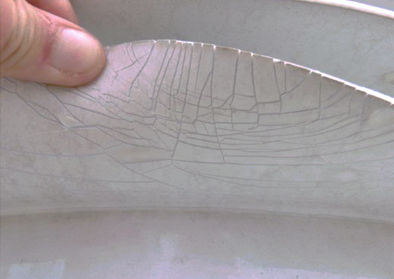
Room temperature vulcanizing (RTV) silicone materials/coatings are widely applied for high voltage insulators to improve performance in harsh environments. But long-term reliability of these coatings depends greatly on resistance to electrical, mechanical and environmental stresses such as corona, tracking/erosion, UV radiation, temperature, moisture and pollutants.
Testing and characterization of these materials is therefore essential for quality control and qualification for use in demanding service conditions as well as for ensuring durability, safety, and consistent performance over their service life. Equally important is understanding the changes that can occur during ageing, since degradation processes can alter electrical, mechanical, chemical, and thermal properties, thereby reducing hydrophobicity, and compromising insulation performance.
This edited contribution to INMR by Dr. Dijana Vrsaljko and other experts at KONČAR Electrical Engineering Institute, in cooperation with the Faculty of Chemical Engineering & Technology at the University of Zagreb, in Croatia reviews how this has been done in the case of a fingerprinting and characterization study of two RTV materials, with and without aluminium trihydrate (ATH) filler. Both were subjected to 1000h of weathering and UV artificial ageing.
A range of analytical techniques including FTIR-ATR, TGA, DSC, XRF, tensile strength, elongation at break, and hardness testing were then employed to establish the change in chemical, thermal, and mechanical properties of these RTV materials. Together, these tests allowed a deeper understanding of the processes that occur within RTV materials during ageing. This work has complemented existing knowledge about surface hydrophobicity, hydrophobicity transfer, and overall coating performance.
RTV Silicone Insulator Coatings
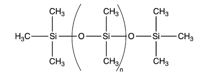
Silicone, the base material for room temperature vulcanizing (RTV) coatings, is a polymer composed of repeating silicon-oxygen (Si–O, siloxane) units. Methyl groups are commonly attached as substituents, forming polydimethylsiloxane (PDMS), a widely used type of silicone in RTV coatings, with its chemical structure illustrated in Fig. 1.
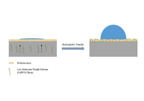
RTV coatings create hydrophobic transfer material (HTM) surfaces on insulators. HTM insulators are crucial in harsh and highly polluted environments such as deserts, coastal, or industrial areas, because pollutants (e.g. sand, salt and organics) can significantly affect insulation performance, especially for high voltage direct current (HVDC) systems.
The coatings are applied as thin layers (typically 0.3 mm to 0.5 mm) to optimize protection without causing thermal stress, either in situ or in factories. Even in such thin layers, coatings repel water, prevent leakage currents, and maintain insulation performance by transferring hydrophobic properties along the insulator surface.
Key material properties of RTV silicone materials include:
• hydrophobicity/water repellency: low surface energy makes the material / coating water-repellent, maintaining performance even in polluted environments;
• thermal and UV stability: Si–O bonds resist heat (up to 200 – 300 °C) and UV degradation, unlike C–C bonds in hydrocarbon polymers;
• electrical protection: reduce leakage currents, flashovers, corona;
• resistance to erosion, low hardness, elasticity, durability and long service life (up to 20+ years depending on material quality and service conditions).

Characterization & Fingerprinting of RTV
Material testing is conducted mostly for quality control but is also important during material development, qualification for use in specific service conditions, during delivery (incoming control), and before installation or coating replacement. In this regard, it is important to verify that materials meet not only certain specific requirements, but also maintain mechanical, electrical, physical, and/or chemical properties suitable for their application. These will ensure quality, durability, and safety, thereby protecting both users and equipment.
Accelerated ageing tests reveal long-term behaviour of materials, enabling end-of-life prediction and early detection of failure modes. This is essential for applications in different electrical equipment and components (e.g. generators, transformers, bushings, cables, insulators, etc.) where failure can lead to costly or dangerous consequences.
As mentioned, RTV silicone materials and coatings are used across demanding service environments. However, over time and under environmental stresses such as humidity, temperature, UV, and natural or human-produced pollutants, their performance can degrade. The results of degradation include microstructural damage, chemical changes, loss of hydrophobicity, and changes in mechanical and insulation properties.
Different groups of tests are therefore needed to evaluate material properties, mechanical strength, hydrophobicity, surface resistance, ageing behaviour, and electrical performance of coatings. These verify durability, protective function and compliance with international standards.
In the case of RTV materials and coatings, the testing scope often required is material ‘fingerprinting’. In the context of RTV coatings, fingerprinting refers to establishing unique material properties with different methods, referencing the profile of the RTV silicone rubber used in the first batch of insulators. Such fingerprinting, along with information on material density and hardness, serves as both material identification and a baseline for quality control in subsequent batches. It is also the procedure to confirm material consistency between different batches from the same manufacturer.
Comparing tested RTV sample properties against its original fingerprint, allows changes in composition or structure to be detected. Such methods can also be used during material substitution to compare RTV materials/coatings supplied by different manufacturers.
The test methods used for RTV fingerprinting are also used for detecting and confirming the presence of aluminium trihydrate, Al(OH)₃. ATH is an inorganic filler commonly used in polymer composites and in silicone rubber compounds for flame retardancy as well as to improve properties such as resistance to tracking, erosion and corona.
Guidelines for fingerprinting of RTV coatings are listed in the literature. For example, the most relevant offer suggestions for methods and information needed to specify the RTV coatings and are shown in Table 8.1 in CIGRE TB 837.
Apart from quality control and material identification, the same fingerprinting test methods can be used to evaluate changes in RTV material properties during ageing, as well as under the influence of external factors including UV, moisture, temperature, electrical stresses and other.
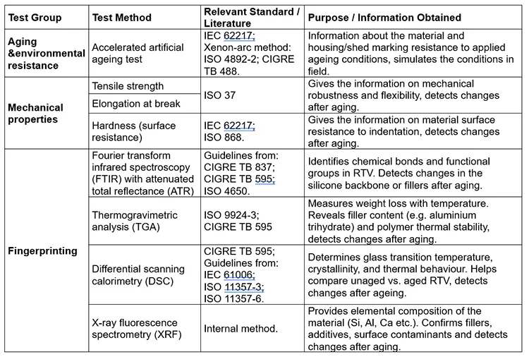
Table 1 presents an overview of the test methods and standards from the literature, which are also applied in this study. The study focused on changes in RTV properties after artificial ageing, particularly in chemical structure and composition, as well as in thermal and mechanical properties.
Research has shown that accelerated ageing tests combined with RTV material characterization using analytical methods such as FTIR, DSC, EDX or XRF and TGA, can effectively detect ageing and chemical degradation. This information can then be used in the field to guide maintenance and component replacement as well as during manufacturing for the purpose of improving formulation.
Experiment
Samples
Samples of two types of RTV material were used for the experiment:
• RTV 1: coating on a glass insulator, without ATH filler,
• RTV 2: bulk material formulated with ATH filler.
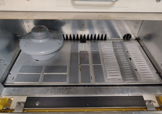
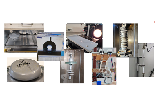
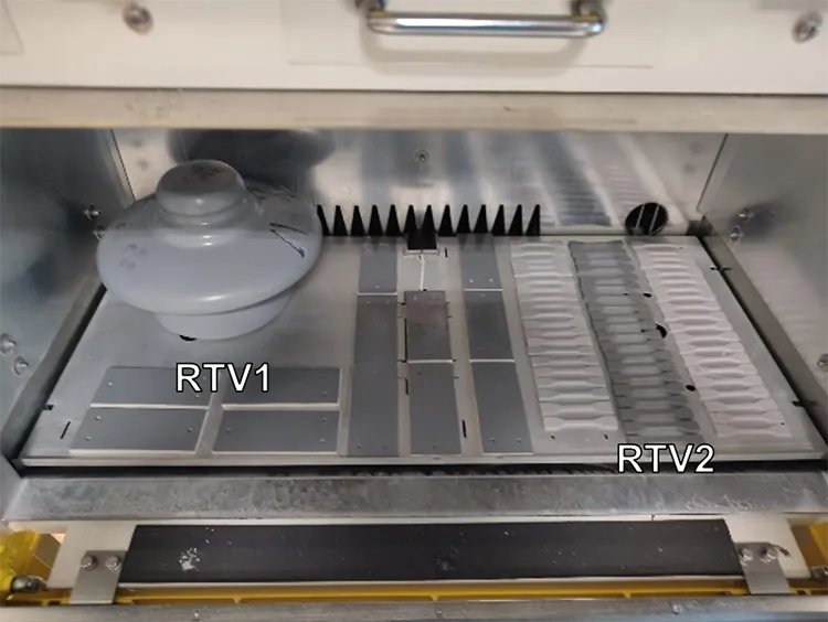
The samples were artificially aged in a UV chamber for 1000h. RTV 1 was aged as a complete insulator (Fig. 2 upper left corner), while standardized dumbbell specimens of RTV 2 were prepared for mechanical testing (Fig. 2, right).
Different properties were measured before and after ageing:
• RTV 1: FTIR, TGA, DSC.
• RTV 2: tensile strength, elongation at break, hardness, FTIR, TGA, DSC.
Methods & Equipment
Artificial Ageing
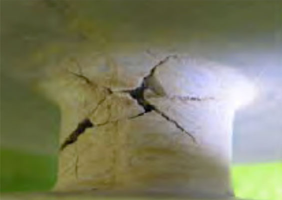
Accelerated ageing tests (thermal, cycling, multi-stress and other) are used to simulate long-term outdoor exposure under controlled laboratory conditions. These enable assessing degradation mechanisms over a shortened timeframe. For RTV materials, these tests provide information on loss of hydrophobicity, material degradation, surface cracking, erosion, and filler depletion. The tests provide information about material behaviour over its service life, enabling different formulations to be compared and supporting material qualification for insulation applications where durability in harsh environments is crucial.
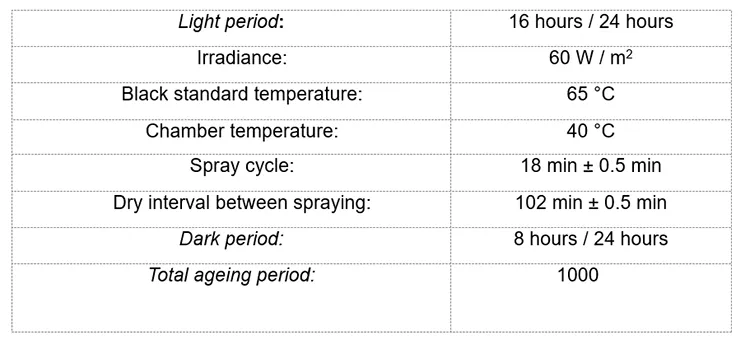
To evaluate materials degradation and to recognize the impact of temperature, UV and humidity on different material properties, RTV 1 and RTV 2 samples (Fig. 2) were subjected to a 1000h UV exposure test using the xenon-arc method, in accordance with ISO 4892-2 with an 8h dark period. Ageing was performed in the Atlas Sunset XXL+ chamber with the main program parameters:
Fourier Transform Infrared Spectroscopy with Attenuated Total Reflection
Fourier transform infrared spectroscopy (FTIR) is a spectroscopic method commonly used to assess the chemical structure and condition of different materials by monitoring vibrational modes of the chemical compounds present. For solid samples, FTIR is often used with an attenuated total reflectance (ATR) module – an accessory that employs an internal reflection element containing a crystal with high refractive index.
FTIR-ATR is widely applied not only to identify matrix materials but also to detect additives and contaminants as well as to monitor ageing of different materials. In the case of RTV silicone coatings, the technique enables rapid, non-destructive surface analysis, directly detecting characteristic chemical bonds from the silicone matrix, as well as vibrations from the ATH filler.
During the analysis, FTIR-ATR scans were recorded in the mid-infrared region from 500 to 4000 cm 1 using a diamond crystal on a PerkinElmer Spectrum Two device. A unique ‘spectral fingerprint’ of the RTV 1 and RTV 2 materials was thus obtained.
Thermogravimetric Analysis
TGA monitors mass loss of the sample in real time during controlled heating under either an inert (nitrogen) or oxidizing atmosphere (oxygen, air). The value of TGA lies in its ability to characterize material composition and thermal stability, offering a unique ‘fingerprint’ of a given formulation that should remain consistent from batch to batch.
For RTV coatings, TGA is especially valuable since it provides insight into filler content (e.g. ATH), polymer degradation behaviour, and overall thermal resistance. This information is essential for assessing material quality, detecting formulation changes, and predicting durability and performance under service conditions in high voltage applications.
The TGA was performed on a TA Instruments TGA Q5500 according to ISO 9924-3 Procedure A on RTV 1 and RTV 2 samples before and after artificial ageing, using the main parameters below:
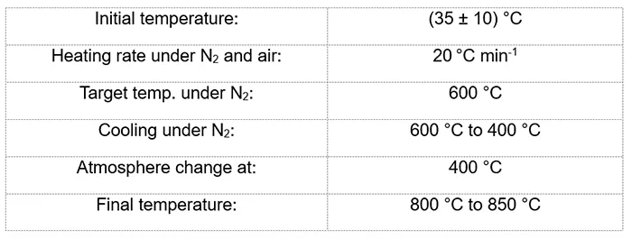
The method is a standard procedure for rubber materials and similar to the test method described in TB 837, except that, according to ISO 9924-3, part of the analysis is performed under oxygen (air) atmosphere.
Differential Scanning Calorimetry
Thermal characterization of materials is important to understand their performance, durability, and degradation mechanisms under various service conditions, especially in conditions where thermal, mechanical, and electrical stability are crucial. DSC is a widely used thermal analysis technique that provides information on material glass transition temperature (Tg), melting temperature (Tm), and crystallization behaviour.
The technique is also used to assess fundamental thermal events, to determine the oxidation induction time (OIT) and oxidation induction temperature (OITP) as measures of a material’s resistance to oxidative degradation. These parameters are usually used for assessing cable insulation and other polymers but could be also used in condition assessment of RTV coatings.
All DSC measurements on RTV 1 and RTV 2 samples were performed using a Mettler Toledo DSC 3+ system. Two experimental set-ups were used:
In the first DSC experiment, the OITP was measured using Guidelines from ISO 11357-6. Samples were heated in air at a rate of 10°C min-1 (flow: 50 mL min-1) up to 300°C. OITP was determined using the tangent intersection method, identifying the point of deviation from the baseline due to the onset of oxidation. Cooling was performed in nitrogen at 20°C min-1.
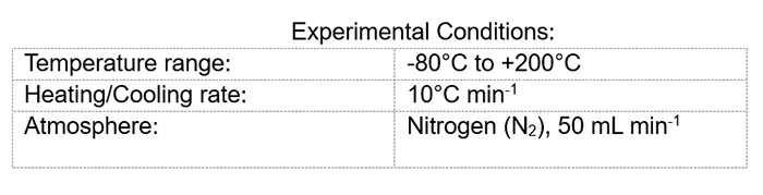
In the second DSC experiment, the heat flow associated with the phase transitions and crystallization behavior of the samples was analyzed. Two heating and cooling cycles at 10°C min-1 under a nitrogen atmosphere (flow rate 50 mL min-1) were performed using the Guidelines from ISO 11357. The first heating scan erased the previous thermal history and the data from the second heating cycle was used to evaluate thermal properties.
X-ray Fluorescence Spectrometry
X-ray fluorescence (XRF) is an analytical technique used to characterize, identify, and determine the chemical composition of materials in solid, liquid, or powdered form. The method is rapid, accurate, and non-destructive, typically requiring minimal sample preparation. It finds application across various industries for material quality control as well as in research and development.
In this study, XRF analysis was performed using the Rigaku NEX DE EDXRF on RTV 1 and RTV 2 samples, both before and after ageing, to monitor changes in chemical composition using an internal fundamental parameter method.
Similar to energy-dispersive X-ray analysis (EDX), which is frequently combined with scanning electron microscopy (SEM/EDX), XRF provides information about the elemental composition of a material. However, unlike EDX or XRF, it cannot detect low atomic number elements, such as carbon (C) and oxygen (O), which in RTV materials are used for evaluating degradation through their ratios with other elements. Despite this limitation, XRF remains valuable for assessing the content of other elements, such as aluminium (Al) and silicon (Si), and for monitoring changes in their amounts and ratios which occur due to ageing and material degradation.
Tensile Strength & Elongation at Break
Tensile strength (TS) and elongation at break (EB) are key mechanical properties used to evaluate the performance of materials. TS represents the maximum stress a material can withstand before failure while EB measures a material’s capacity to stretch before break, giving information on its flexibility and emphasizing the ability to deform before failure (ductility).
Together, these parameters are crucial for assessing how materials respond to mechanical loads, selecting suitable formulations for specific applications and monitoring changes due to environmental or artificial ageing processes. TS and EB were measured on unaged and aged Type 3 dumbbell specimens from RTV 2 material, in accordance with ISO 37, except for specimen thickness which was 6 mm and thus greater than specified in the standard. The measurements were performed on a ZwickRoell ProLine 20 kN universal testing machine under standard laboratory conditions.
Hardness
Measuring and evaluating change in hardness of materials is important because hardness reflects a material’s mechanical integrity, stiffness, and resistance to surface deformation. Changes in hardness after ageing or environmental exposure can indicate crosslinking, chain scission, or filler migration, which affect flexibility, wear resistance, and overall performance. For RTV coatings, monitoring hardness helps assess surface erosion, embrittlement, or softening/hardening, providing insight into durability and remaining service life in high voltage insulation applications.
Hardness was measured on unaged and aged specimens from RTV 2 material, in accordance with ISO 868 using a Shore A durometer. The samples were conditioned overnight at (23 ± 2)°C and measurements were performed at the same ambient temperature. Hardness readings were taken (15 ± 1) seconds after the contact between the sample surface and the Shore A indenter.

Results & Discussion
After artificial ageing of the RTV 1 and RTV 2 materials under the conditions specified above, different tests were performed according to the sample shape and form. As mentioned, the RTV 1 sample is a coating on a glass insulator, confirmed to be without ATH filler during fingerprinting and suitable for FTIR, TGA and DSC measurements. The RTV 2 sample is a bulk material tested for qualification, formulated with ATH filler and suitable for FTIR, TGA, DSC, tensile strength, elongation at break, and hardness measurements.
A. FTIR
Comparison of the FTIR spectra for RTV 1 (see Fig. 3) and RTV 2 (see Fig. 4) highlights key differences in their composition. Both materials can be identified as silicone rubber, having a silicone backbone with characteristic bands at 1000–1100 cm-1 for Si–O–Si stretching, ~1260 cm-1 for Si–CH3, and ~750 cm-1 for Si–(CH3)2. However, there are differences in the shape of the bands below 1500 cm 1.
These differences confirm that RTV formulations can vary between manufacturers, meaning there is no unique formulation. Therefore, FTIR provides a chemical fingerprint of each formulation. In addition to differences in the main polymer composition, RTV 2, unlike RTV 1, contains ATH, as indicated by O–H stretching bands in the 3200–3600 cm-1 region and Al–O–H bending / stretching vibrations in the 550–730 cm-1 range.
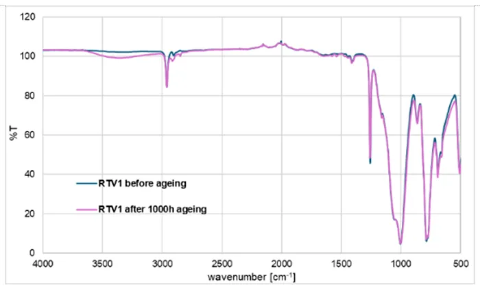
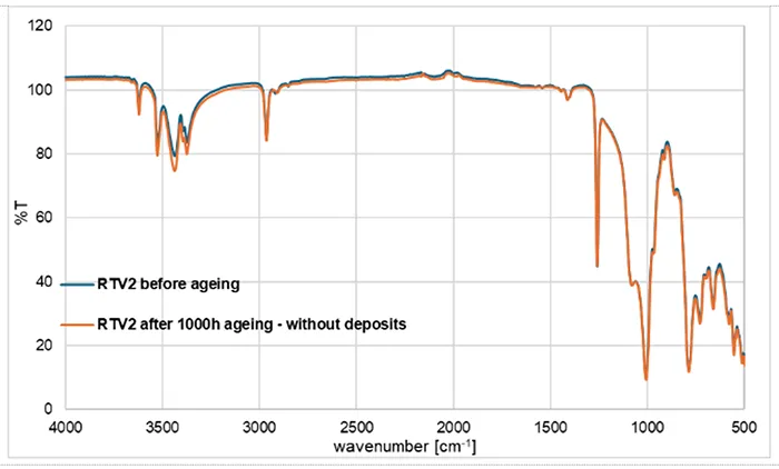
Fig. 3 presents the FTIR spectra of RTV 1 before and after 1000h of artificial ageing. The spectra largely overlap (blue: unaged; pink: aged) except for small changes. After ageing, the Si–O–Si band (1000–1100 cm 1) shows slight intensity changes, suggesting minor rearrangements or scission in the siloxane backbone.
The Si–CH3 band (~1260 cm-1) decreases slightly, indicating partial oxidation or loss of methyl groups, while the CH stretching bands (~2900–2960 cm-1) also weaken, consistent with oxidative degradation of the methyl side groups. These changes are commonly reported as surface oxidation markers in RTV materials.
The most noticeable difference appears in the broad O–H region (~3200–3600 cm-1). After ageing, the spectrum shows a slight increase, suggesting formation of surface silanol (Si–OH) groups. This transformation is a typical outcome of oxidative and hydrolytic attack, leading to partial hydroxylation of the surface and reduction in hydrophobicity while the bulk siloxane network remains largely intact.
Fig. 4 presents the FTIR spectra of RTV 2 before and after 1000h of artificial ageing. The spectra largely overlap (blue: unaged; orange: aged) except for some slight changes, as with RTV 1. The Si–O–Si band in the 1000–1100 cm-1 region is unchanged, indicating the silicone network remains intact after ageing.
Only small, surface-limited changes are suggested, such as a small difference in the O–H region (~3200–3600 cm-1). The aged spectrum shows a slight increase in this region, consistent with a small amount of surface silanol formation or adsorbed moisture. The change is minor. The lack of large spectral changes indicates that the bulk chemical structure of RTV 2 is stable under the applied accelerated ageing conditions.
FTIR-ATR recordings in Figs. 3 and 4 were performed on cleaned material surfaces, because visible white deposits were observed on the surface. This is important to emphasize because of the interference that can occur due to surface contamination. The example of the FTIR spectra for the RTV 2 material after ageing, with and without deposits on the surface is demonstrated in Fig. 5.
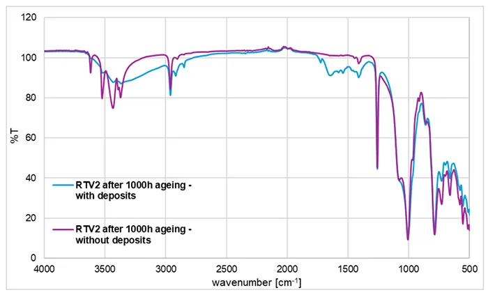
The deposits on the RTV 2 material formed during artificial ageing and partially overlap with the characteristic polymer bands of the material surface. The additional bands observed in the pink spectrum in Fig. 5 disappear after wiping with alcohol, confirming that they arise from removable surface deposits rather than from bulk polymer degradation.
Because ATR-FTIR probes only a few surface micrometres of a sample, even a very thin deposit layer can dominate the measured spectra and interfere with the silicone signals. The broad band between 3200–3600 cm 1 can be attributed to water adsorbed on hygroscopic inorganic salts formed by migration of different additives/fillers from the bulk or from water used for rain simulation.
The broad band with multiple peaks between 1400–1700 cm 1 can be explained by presence of carbonate anions in various inorganic salts. In contrast to deposits, the chemical modification of the RTV surface, like formation of covalently bound silanols (Si–OH), mentioned in the text explaining Figs. 3 and 4, is not removed by wiping with the solvent. Silanol formation is an irreversible surface-chemical ageing effect that requires chemical modification or thermal treatment to reverse.

B. TGA
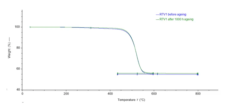
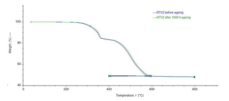
TGA monitors mass loss during controlled heating under either an inert (nitrogen) or oxidizing atmosphere as explained earlier. The result is a unique thermogram or thermogravimetric (TG) curve as illustrated in Fig. 6 for the RTV 1 material and in Fig. 7 for the RTV 2 material.
In general, all thermograms can be divided in two main sections: pyrolysable and non-pyrolysable components in the material. The sections are visible in distinct mass-loss steps in specific temperature ranges and atmospheres (nitrogen, oxygen, or air). In a nitrogen atmosphere the mass loss occurs due to the evaporation, decomposition and pyrolysis of organic components (in most methods up to 300°C) and the base polymer (in most methods up to 600°C).
During mass-loss steps in nitrogen atmosphere, pyrolysable compounds of the material are removed. The degradation of the non-pyrolysable components continues with complete combustion and degradation in an oxidizing atmosphere at temperatures mostly above 600°C. For RTV 1 and RTV 2 materials, total pyrolysis occurs during the first heating period in a nitrogen atmosphere, with no significant mass-losses in the oxygen atmosphere. The final residue consists of ash and inorganic substances, which, depending on the fillers and additives present in the material formulation (i.e., RTV), can include oxides of aluminium, silicium, calcium, titanium, and others.
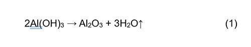
The most notable difference between the thermograms in Figs. 6 and 7 is that the thermogram for RTV 2 sample (Fig. 7) exhibits two distinct mass losses. The first mass loss, occurring between 300°C and 400°C, is attributed to release of water bound within the chemical structure of ATH and can be illustrated by the reaction (1). The RTV 1 sample does not exhibit this initial mass loss, and when considered together with the FTIR spectrum (Fig. 3, does not contain sharp bands in the 3200–3600 cm-1 region), this provides evidence that it does not contain ATH.
before and after artificial ageing.
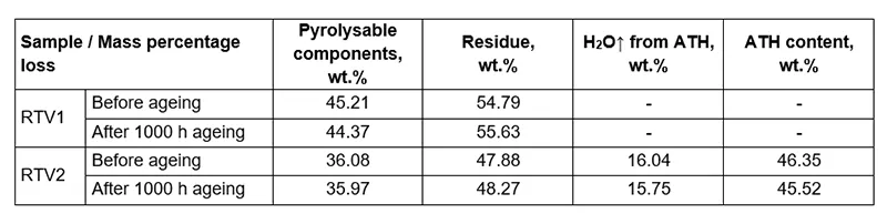
Table 2 presents the results for the mass fractions (wt.%) of individual components in RTV 1 and RTV 2 materials before and after artificial ageing. The content of ATH in RTV 2 was calculated from the stoichiometric ratio using reaction.
in RTV 1 & RTV 2 materials Before & After Artificial Ageing
Although the differences in the component mass fractions before and after ageing are not high (see Table 2), they indicate changes in the material due to the applied ageing conditions. Thermogravimetric analysis of RTV 1 and RTV 2 before and after 1000h ageing shows that both materials exhibit a right-shift in their decomposition curves, indicating increased apparent thermal stability.
Quantitative evaluation shows a small reduction in the pyrolysable fraction with a corresponding increase in inorganic residue for both systems. The mass fraction change for RTV 1 is -0.84 wt.% pyrolysable components with +0.84 wt.% residue, and for RTV 2, -0.11 wt.% pyrolysable components with +0.39 wt.% residue.
These changes are consistent with ageing induced cross-linking reactions (leading to higher molecular weight), loss of low molecular weight and volatile species, or potentially the formation of more thermally stable inorganic residue. In RTV 2, which contains ATH, the ATH content decreased slightly from 46.35 wt.% to 45.52 wt.% after ageing, indicating minor dehydroxylation or transformation of ATH during the exposure to artificial ageing conditions described above.
RTV 1, which contains no ATH, shows larger compositional change, while RTV 2 remains comparatively stable, reflecting the stabilizing effect of ATH filler despite the small decrease in ATH content. Overall, the results suggest that ageing promotes crosslinking in the material, which delays thermal degradation in TGA, even though such processes negatively influence surface hydrophobicity, hydrophobicity transfer ability and mechanical flexibility of RTV materials/coatings.

DSC
1. First Experiment
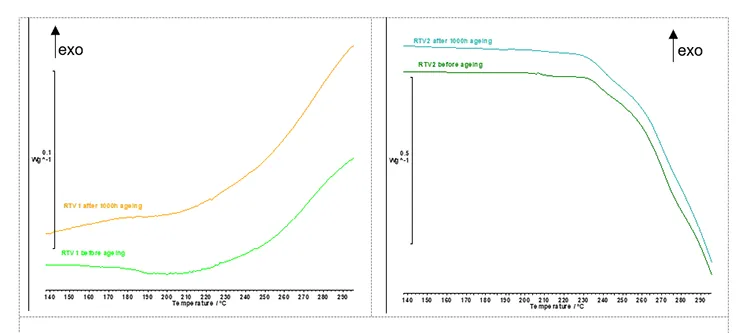
OITP was performed using the method parameters described above. OITP represents the material thermal stability and indicates the temperature at which the oxidation starts. DSC curves for RTV 1 material before and after artificial ageing are shown in Fig. 8 – left and for RTV 2 material in Fig. 8 – right. The determined onset temperatures for both materials are listed in Table 3.
before and after artificial ageing.
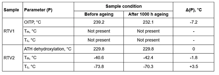
In Fig. 8, the DSC curve for RTV 1 (without ATH) shows a distinct rise corresponding to the onset of an exothermic oxidation reaction, which defines the oxidation induction temperature point (OITP). In this oxidative DSC recordings (Fig. 8-left, air atmosphere) RTV 1 shows a clear oxidation-induction temperature point (OITP). Before ageing, the OITP is 239.2°C and after 1000h of artificial ageing it drops to 232.1°C. This decrease indicates reduced oxidative stability after UV/heat/rain exposure, consistent with consumption or leaching of stabilisers and formation of more oxidation prone species during aplied ageing conditions.
In contrast to RTV 1, the DSC curve for RTV 2 (with ATH filler) exhibits an endothermic signal associated with the dehydroxylation of ATH described with the Reaction (1). This endothermic effect most probably partly overlaps with the exothermic oxidation of the polymer in the recorded temperature range, giving the appearance of a downward shift in the DSC baseline. RTV coatings require high ATH content (typically ≥27 wt.%) to ensure good tracking and erosion resistance. In addition, ATH provides flame retardancy in many polymeric materials (e.g. cable insulation, plastic housings, paintings) due to its endothermic decomposition and release of water vapour, which cools the burning area and dilutes the combustible gases near the flame.
2. Second Experiment
In the second DSC experiment analysed heat flow associated with the phase transitions and crystallization behaviour of the samples. Two heating and cooling cycles were performed on RTV 1 and RTV 2 material before and after artificial ageing as described above. Fig. 9 depicts representative thermograms of the two cycles for both materials before ageing.
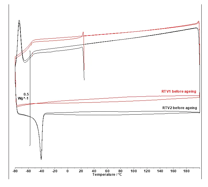
RTV 1 and RTV 2 materials before artificial ageing.
In Fig. 9 for RTV 1, the red DSC curves recorded in the applied temperature range show no detectable melting (Tm) or crystallization (Tc) peaks. This is consistent with an essentially amorphous or highly cross-linked silicone material.
In contrast to RTV 1, the black DSC curves for RTV 2 (see Fig. 9) exhibit sharp low temperature phase transitions below -20°C. Phase transitions are evident as an endothermic peak (Tm) and exothermic peak (Tc) indicating the materials’ semi-crystalline nature.
Fig. 10 presents segments of the DSC thermograms for the RTV 2 material, displaying melting peaks (Tm) on the left and crystallization peaks (Tc) on the right before and after artificial ageing. Table 3 lists values for Tm and Tc.
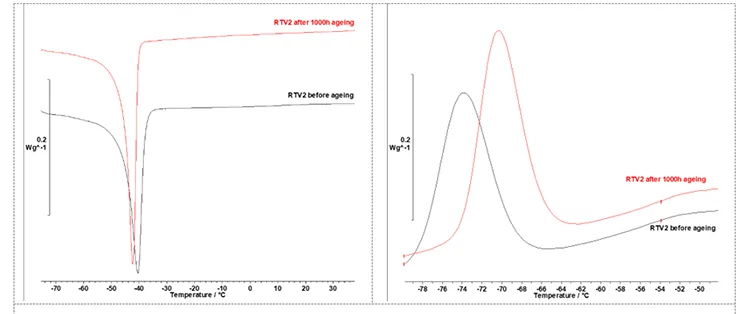
for RTV 2 material before and after artificial ageing.
After 1000h of artificial ageing, the DSC phase transition temperatures of RTV 2 shift:
i. Tm decreases slightly from -40.6°C to -42.4°C while Tc increases from -73.8°C to -70.3°C. These changes are consistent with UV/thermo-oxidative ageing at moderate temperatures, which produces chemical modifications at and near the surface (chain-scission and oxidative cross-linking, formation of oxidation products and new chain ends),
ii. the melting enthalpy (ΔHm) increased slightly from 9.33 to 9.63 J·g⁻¹ and the crystallization enthalpy ΔHc increased slightly from 8.10 to 8.90 J·g⁻¹ which may reflect a larger number of smaller, less stable crystallites,
iii. the glass transition baseline shifts (Tg) for both materials RTV1 and RTV2 cannot be observed in the DSC curves because they most likely appear in lower temperature regions (below – 80ºC).
XRF
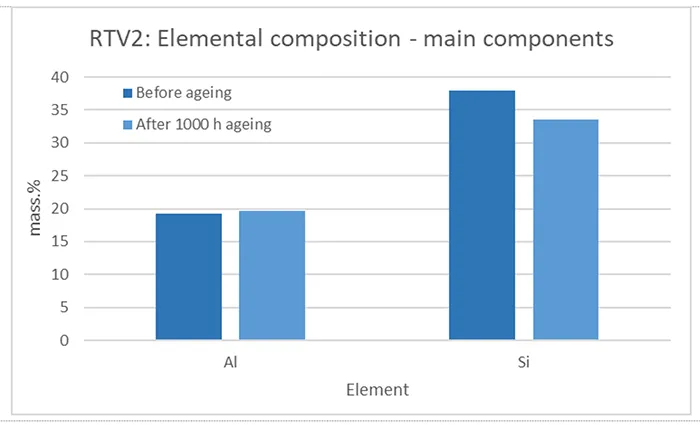
As mentioned, XRF provides information about the elemental composition of a material but is limited in detecting low atomic number elements such as carbon (C), oxygen (O), nitrogen (N). Despite this limitation, XRF remains valuable for assessing the content of other elements, such as aluminium (Al) and silicon (Si) as well as for monitoring changes in their amounts and ratios due to ageing and material degradation. Figs. 11 to 14 shows results of XRF analysis performed on RTV 1 and RTV 2 materials.
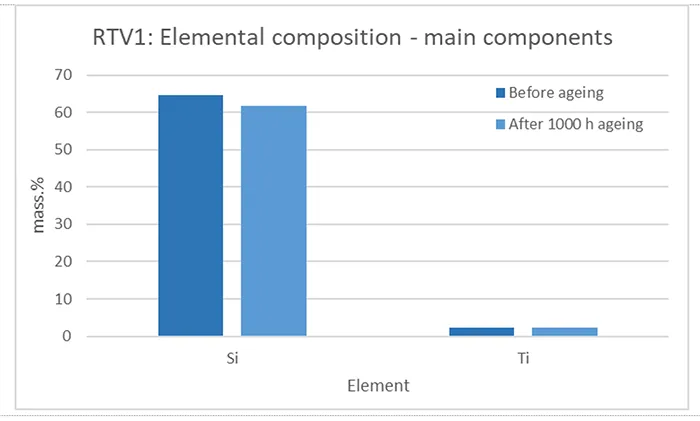
From the elemental composition in Fig. 11 it is evident that RTV 1 does not contain aluminium (present only in trace amounts), which is the main element in aluminium hydroxide. Therefore, it can be concluded that the RTV 1 material does not include ATH filler. This finding was previously confirmed by FTIR and TGA analysis.
In contrast to RTV 1, the RTV 2 material contains a significant amount of aluminium (see Fig. 12), consistent with the presence of ATH and, (having in mind the method limitations) comparable to the stoichiometrically calculated amount noted in Table 2. The presence of ATH was also previously confirmed by FTIR and TGA analysis.
In both materials, RTV 1 and RTV 2, silicon (Si) is present in the highest mass percentage, which is logical since it is the main structural component of the polymer. Beside Si and in contrast to RTV2, RTV1 contains titanium (Ti). Titanium may originate from TiO2, which is used as a white pigment for improving opacity and brightness, has a high refractive index and serves as a UV light scatterer and absorber, protecting the silicone matrix from photo-degradation and extending outdoor durability. As an inorganic filler, TiO2 can also enhance mechanical properties such as hardness and abrasion resistance, while in some formulations it influences the dielectric performance of RTV material/coatings.
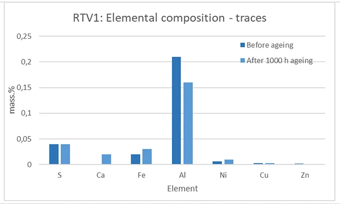
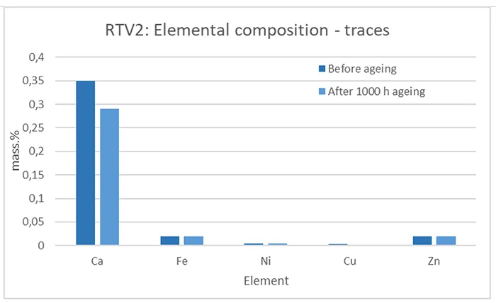
Beside the main elements listed in Figs. 11 and 12, RTV 1 and RTV 2 consist of trace elements (≤ 1 mass.%) originating from different components added to the base polymer formulation, such as fillers, plasticizers, antioxidants, and other additives for improving various material properties.
In all graphs (Figs. 11–14), small changes in the mass.% of elements can be observed when comparing before and after artificial ageing, indicating different processes and chemical reactions initiated by the applied ageing conditions. These suggest decomposition, re-combination, leakage and evaporation of components, complementing the results and ageing processes explained in the sections above that deal with the other test methods.

Tensile Strength, Elongation & Hardness
Tensile strength and elongation at break were measured on RTV 2 samples as described above. The Shore A hardness of RTV 2 samples was measured as described.
The TS for RTV 2 material before and after artificial ageing is illustrated in Fig. 15, the EB in Fig. 16 and the change of Shore A hardness in Fig. 17. The values indicated are the median of 5 independent measurements.
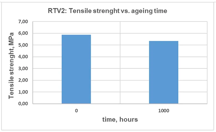
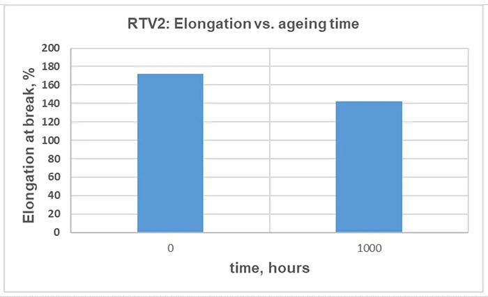
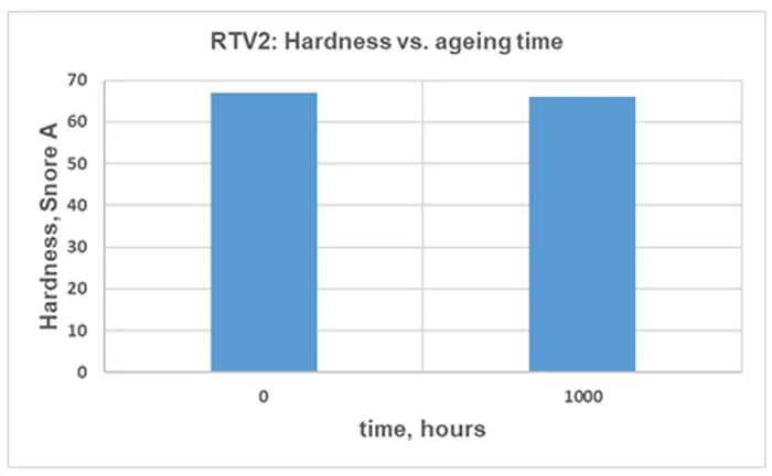
A modest reduction in TS, EB and hardness after 1000 h of artificial ageing can be observed in Figs. 15, 16 and 17. This is a commonly observed trend, and the magnitude varies with the material formulation and ageing conditions.
Although the change in mechanical properties of the RTV 2 material after 1000 h of artificial ageing is not significant, it is consistent with results from other measurements, confirming chemical and structural changes in the material due to 1000h of exposure to artificial ageing conditions.
Conclusions
Fingerprinting techniques provide an effective means of identifying compositional changes in RTV silicone materials during ageing. While individual methods present certain limitations due to the nature of the tests (such as FTIR requiring surface cleaning and XRF being primarily sensitive to filler composition) their combined application enables a more comprehensive characterization.
Therefore, complementary use of analytical techniques is essential to capture both chemical transformations and functional property degradation. This allows better understanding material ageing and a more robust assessment of an RTV silicone marterial’s performance over its service life.
No single method or artificial ageing test can cover and identify all material changes and the associated complexity of processes present under actual environmental and exploitation conditions. Combined use of complementary techniques provides a more complete understanding of the ageing processes that can occur. By integrating molecular spectroscopic analysis, filler identification, and evaluation of functional properties, fingerprinting becomes a powerful diagnostic approach to assess the condition of a material. It also complements existing knowledge about surface hydrophobicity, hydrophobicity transfer and overall coating performance.

Literature
[1] CIGRE WG B2.69 Technical Brochure 837, “Coating for improvement of electrical performance of outdoor insulators under pollution conditions,” 2021.
[2] CIGRE WG D1.14 Technical Brochure 478, “Important Material Properties of RTV Silicone Rubber Insulator Coatings,” 2011.
[3] IEC TR 62039:2021, “Selection guidelines for polymeric materials for outdoor use under HV stress”.
[4] CIGRE WG D1.14 Technical Brochure 488, “Resistance to Weathering and UV Radiation of Polymeric Materials for Outdoor Insulation,” 2012.
[5] IEC 62217:2012, “Polymeric HV insulators for indoor and outdoor use – General definitions, test methods and acceptance criteria”.
[6] D. K. D. Ghosh, “Degradation and Stability of Polymeric High-Voltage Insulators and Prediction of Their Service Life through Environmental and Accelerated Aging Processes,” ACS Omega, vol. 3, p. 11317−11330, 2018.
[7] CIGRE EG D1.27 Technical Brochure 595, “Fingerprinting of Polymeric Insulating Materials for outdoor use,” 2014.
[8] ISO 4892-2:2013+Amd 1:2021, “Plastics — Methods of exposure to laboratory light sources — Part 2: Xenon-arc lamps + Amendment 1: Classification of daylight filters”.
[9] ISO 37:2024, “Rubber, vulcanized or thermoplastic — Determination of tensile stress-strain properties”.
[10] ISO 868:2003, “Plastics and ebonite — Determination of indentation hardness by means of a durometer (Shore hardness)”.
[11] ISO 4650:2012, “Rubber — Identification — Infrared spectrometric methods”.
[12] ISO 9924-3:2024, “Rubber and rubber products — Determination of the composition of vulcanizates and uncured compounds by thermogravimetry – Rubber and rubber products — Determination of the composition of vulcanizates and uncured compounds by thermogravimetry — Part 3”.
[13] IEC 61006:2004 , “Electrical insulating materials – Methods of test for the determination of the glass transition temperature (withdrawn)”.
[14] ISO 11357-3:2025, “Plastics — Differential scanning calorimetry (DSC) — Determination of temperature and enthalpy of melting and crystallization”.
[15] ISO 11357-6:2025, “Plastics — Differential scanning calorimetry (DSC) — Part 6: Determination of oxidation induction time (isothermal OIT) and oxidation induction temperature (dynamic OIT)”.
[16] V. Haramija et al., “Accelerated Laboratory Aging of Synthetic Ester Dielectric Liquid,” IEEE Transactions on Dielectrics and Electrical Insulation, vol. 32, no. 1, pp. 367-374, 2025.
[17] M. Pirc et al., “Chemical analysis of thermally aged cables in nuclear power plants,” Journal of Energy Technology, vol. 18, no. 1, pp. 35-54, 2025.
[18] C. A. Ferreira et al., “Effect of Artificial Aging on Polymeric Surge Arresters and Polymer Insulators for Electricity Distribution Networks,” Polimeros, vol. 21, no. 5, pp. 436-442, 2011.
[19] D. Gnanasekaran, “Physical and Chemical Investigations on Silicone Insulating Rubber (SiR) Composite,” Power Research, vol. 22, no. 2, pp. 227-233, 2024.
[20] H. Yang et al., “Study on ageing characteristics and evaluation methods of RTV silicone rubber in high humidity area,” PLoS ONE, vol. 16, no. 6, 2021.
[21] J. Chen et al., “Study on the Influence of Accelerated Aging on the Properties of an RTV Anti-Pollution Flashover Coating,” Polymers 2023, 15, 751., vol. 15, no. 3, 2023.
[22] S. A. Saleem et al., “End-of-Life Evaluation of RTV Coated Porcelain and Glass Insulators Under Pollution Conditions,” Power Research – A Journal of CPRI, 9–15., vol. 5, no. 1, 2009.
[23] L. Mu et al., “Study on material and mechanical characteristics of silicone rubber shed of field aged 110 kV composite insulators,” Sci Rep 13, 16889 (2023). https://doi.org/10.1038/s41598-023-35701-8.
[24] Z. Zhang et al., “Application of Infrared Spectroscopy in Research on Aging of Silicone Rubber in Harsh Environment. Polymers 2022, 14, 4728.,” Polymers, vol. 14, 2022.
[25] H. Kaur et al., “Surface Structural Changes in Silicone Rubber Due to Electrical Tracking,” Appl Spectrosc, 2024.
[26] D. Verrica et al., “ATR–FTIR Spectral Analysis and Soluble Components of PM10 And PM2.5 Particulate Matter over the Urban Area of Palermo (Italy) during Normal Days and Saharan Event,” Int. J. Environ. Res. Public Health, vol. 16, no. 14, 2019.
[27] M. H. Raza et al., “Surface Recovery Investigation of Silicone Rubber Composites for Outdoor Electrical Insulation under Accelerated Temperature and Humidity,” Polymers 2021, 13, 3024., vol. 13, no. 18, 2021.
[28] E. A. Mwafy et al., “Dynamic mechanical characteristics of aged silicone rubber blend,” Polymer Bulletin, vol. 80, p. 9015–9032, 2023.
[29] Z. Wang et al., “Effects of aging on the structural, mechanical, and thermal properties of the silicone rubber current transformer insulation bushing for a 500 kV substation,” SpringerPlus, vol. 5, 2016.
[30] X. Wen et al., “RTV Silicone Rubber Degradation Induced by Temperature Cycling,” Energies, vol. 10, 2017.
[31] B. S. Vasile et al., “Thermally Activated Al(OH)3 Part II—Effect of Different Thermal Treatments,” Ceramics, vol. 4, no. 4, pp. 564-575, 2021.
[32] M. T. Nazir et al., “Flame Retardancy and Excellent Electrical Insulation Performance of RTV Silicone Rubber,” Polymers 2021, 13,, vol. 13, no. 17, 2021.
[33] A. Morawska-Chochół et al., “The Effect of Aging Process Conditions on the Thermal Properties of Poly(Dimethylsiloxane)-Based Silicone Rubber,” Materials, vol. 17, no. 22, 2024.
[34] S. Zeng et al., “Effects of combined UV-tensile aging on structural and electrical properties of high temperature vulcanized silicone rubber in composite insulators,” RSC Advances, vol. 33, 2025.
[35] J. White, S. K. De and K. Naskar, Rubber Technologist’s Handbook, Volume 2, vol. 6, Shawbury, Shrewsbury, Shropshire, UK: Smithers Rapra Technology Limited, 2002, pp. 1111-1132.
[36] X. Wang et al., “Effect of Ultraviolet—A Radiation on Alicyclic Epoxy Resin and Silicone Rubber Used for Insulators,” Polymers , vol. 14, no. 22, 2022.