Silicone coatings have traditionally been applied mainly to mitigate insulator contamination problems at substations but the past 25 years have seen their application to overhead lines grow significantly. As this process evolved, coating line insulators moved progressively from something performed mostly in the field to industrial scale application in specialized factories to allow for greater consistency, reliability and economy.
This edited past contribution to INMR by Jean-Marie George, Scientific Director at Sediver in France, discussed requirements to ensure satisfactory long-term performance of a coating. First, selecting the most appropriate coating material is key to achieving lasting hydrophobicity as well as a resistance to erosion – even under severe pollution and related corona activity. Second is the coating process itself which must be carefully considered and controlled to avoid accelerated degradation in performance.


Selecting Coating Material
Most of the diverse formulations of silicone coatings now available on the market are classified as RTV2, meaning that a chemical agent is added to promote curing. Curing of RTV1 materials, by contrast, relies only on exposure to ambient moisture.
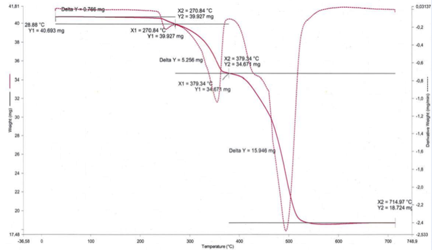
Based on 40 years of laboratory and field experience at Sediver – a supplier of toughened glass insulators – it has been determined that selecting a coating should be based on physico-chemical parameters that influence its performance during ageing tests, whether these are type tests or type and sample tests. For example, one obvious test is verifying hydrophobicity, with an expectation of HC1 based on IEC TS 62073 as reference. In addition, CIGRE Technical Brochure 595 explains how to establish the fingerprint of a silicone coating using similar requirements to those used for polymeric housing materials. This fingerprint must include the following: thermal gravimetric analysis (TGA); Fourier transformed infra-red (FTIR) analysis; and density.

TGA is intended to demonstrate the presence and proportion of alumina trihydrate (ATH) contained in the silicone. While some coatings have neither ATH nor a substitute, multi-stress ageing tests confirm that such fillers inherently reduce risk and rate of erosion in harsh service environments.
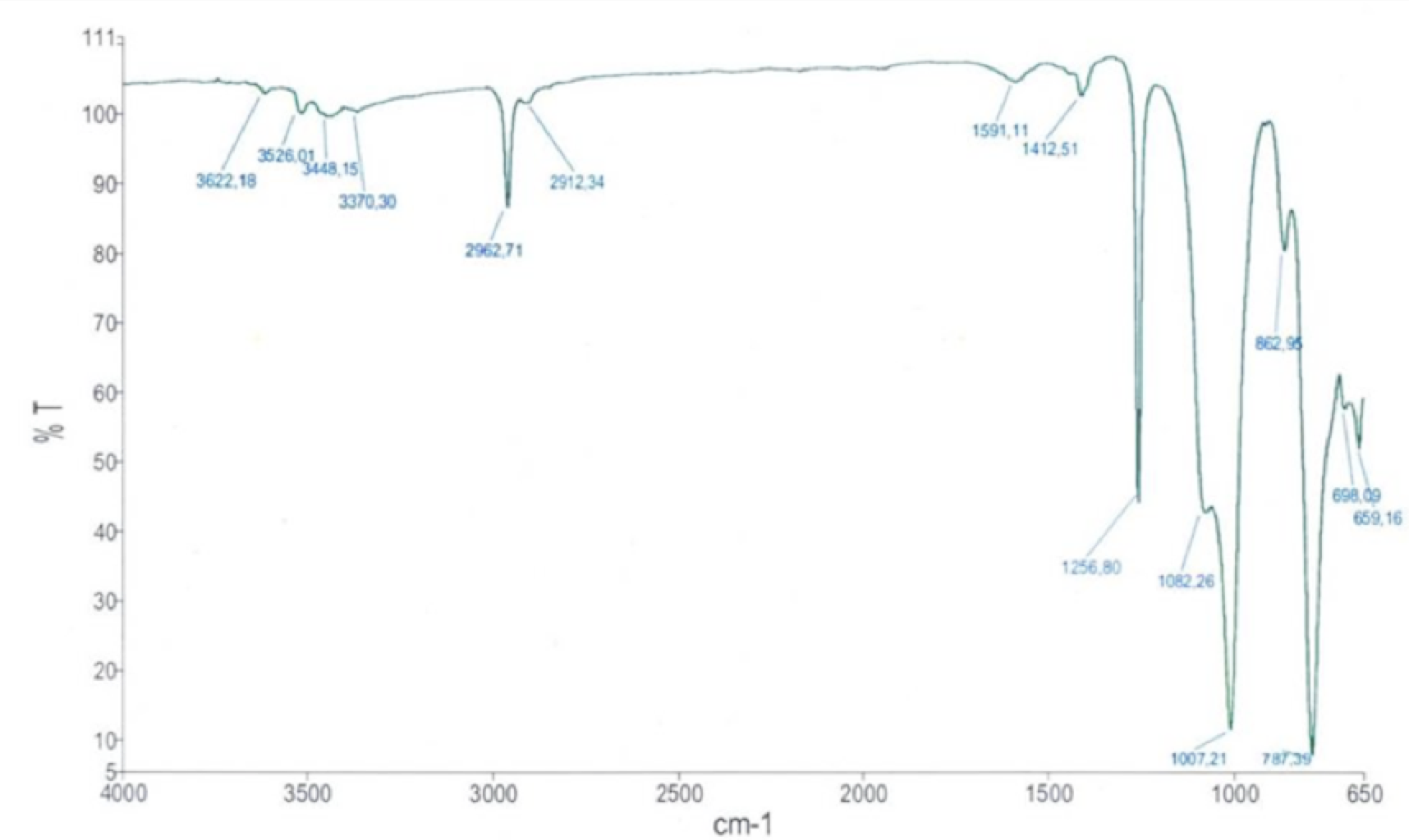
FTIR analysis, by contrast, provides a spectrum where various key components are identified by their specific absorption bands (see Fig. 2). FTIR and TGA procedures therefore help validate approved materials through type tests as well as ensure consistency of supply of these materials by means of sample tests. Specific gravity is another useful indicator in this regard.
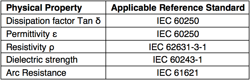
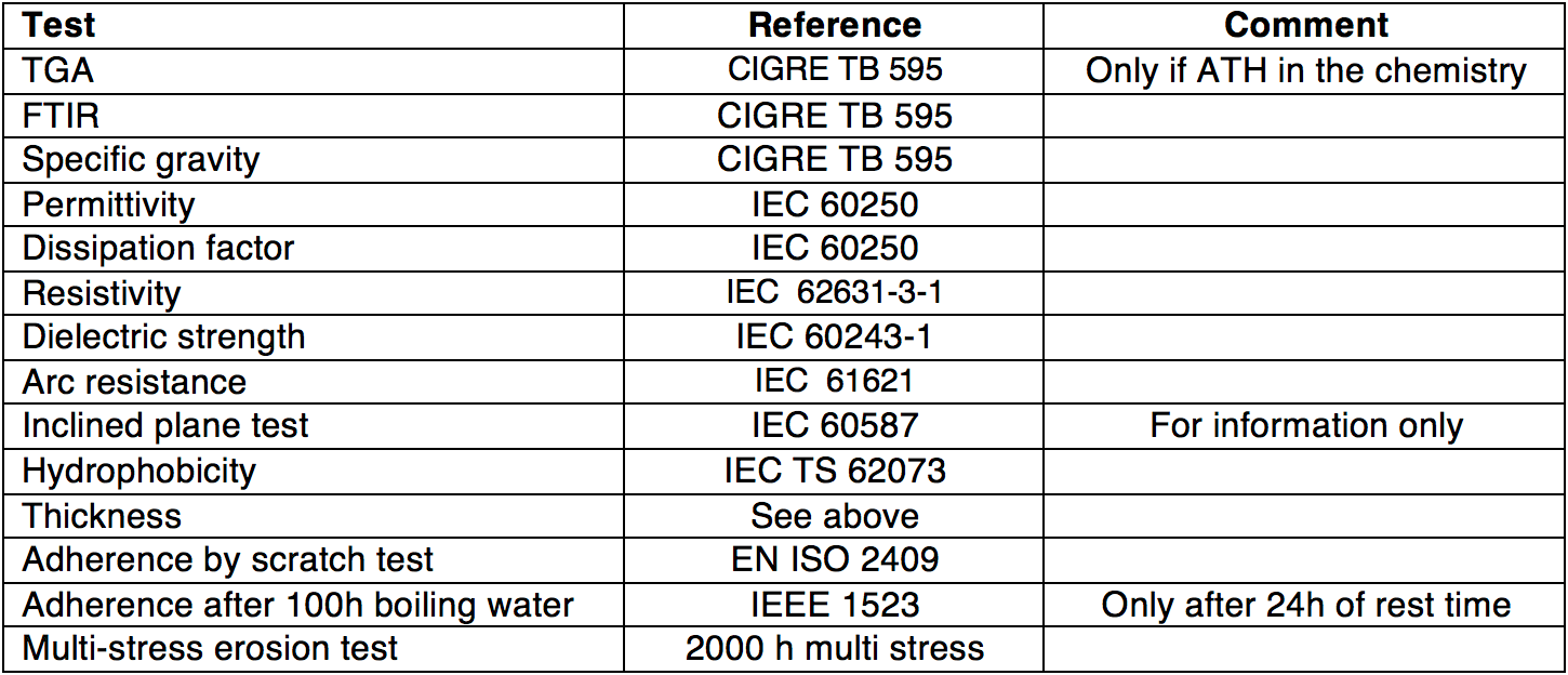
Additional physico-chemical parameters (outlined in Fig. 3) should also be considered with the goal of establishing reference properties of the silicone used in a coating intended for electrical applications.

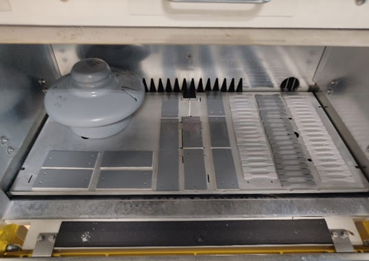
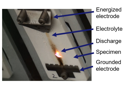
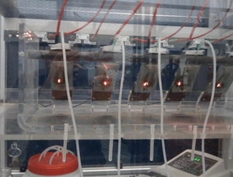
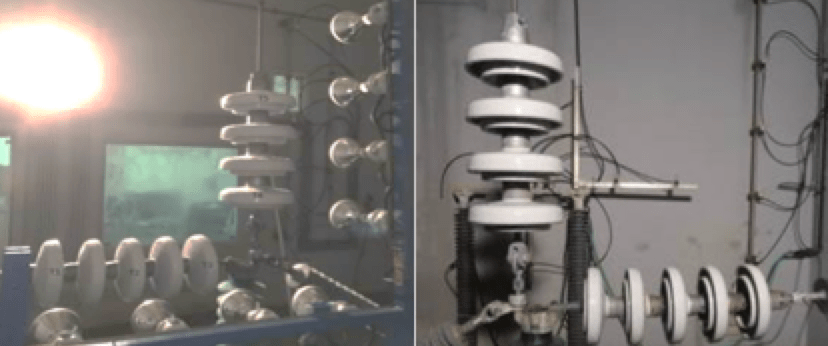
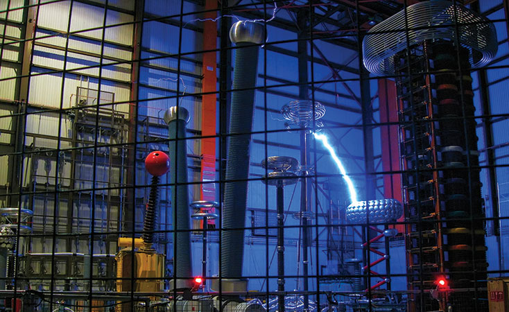
Once the applicable physico-chemical parameters of a coating have been established, there is the need to evaluate its electrical performance. The most relevant parameter here is its ability to sustain arcing without excess damage from erosion. Several tests should be considered in this regard, including the arc resistance testing shown in Fig. 4.
For example, a relatively well-known test described in IEC 60587 is the inclined plan test. Fig. 5 illustrates the test arrangement and typical results. Silicone coatings usually meet the requirement of 1°3, 5 when using Method 1 with 6h voltage steps. This test is easy to perform on LSR and HTV silicone rubber compounds that are easily molded into large sections. However it is more challenging to perform in the case of coatings where less consistency is obtained due to the difficulty of pouring the coating into an appropriate mold. Another approach is therefore to apply the coating over a ceramic tile. Fig. 6 shows results for the same coating material being tested with different preparation procedures. Fluctuations show withstand results at 1A4.5, but with questionable consistency. Referencing this test in any coating specification therefore requires a clear description of the protocol by which samples are to be prepared.
A more pragmatic approach is evaluating erosion resistance of a coating when applied over an insulator. There are tests such as the 1000h salt fog or the 5000h multistress test in the case of polymeric materials. However, these are designed mainly to test erosion resistance of relatively thick samples (3 mm minimum for most polymeric insulators) versus typical coating thicknesses that average only about 300 µm.

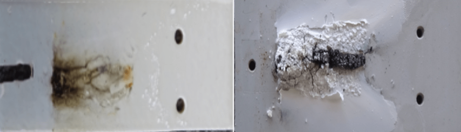
Another test, adopted by Italian TSO, Terna, has shown an excellent capacity to discriminate among different coating chemistries and is now used as well in many other utility specifications. Fig. 7 shows the test protocol, where acceptance criteria require the coating not to erode to the surface of the glass or porcelain substrate and with no more than three flashovers allowed during the test.
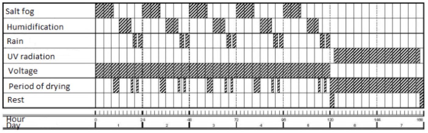
This test can be performed on any type of insulator and also requested for any given shape/geometry. Typical electrical stress level during the test is achieved with a USCD of 37mm/kV and 40g/l salinity. Flow in the test chamber is 1.33 dl/h/m3 and preparation of the salt fog must comply with IEC EN 60507 §7 & 8. Each wetting period lasts 6 hours and vapour is produced by evaporation of a volume of water contained in a tank placed inside the test chamber. Quantity of water evaporated shall be 33g/h/m3 over a maximum of 75 minutes at the start of the wetting period and each period of rainfall lasts 4 hours, divided into periods of 2 hours each. Rain flow shall be 1.5 mm/min and, between the two periods of rain, a one-hour rest period is allowed. Rain characteristics have to comply with IEC 60060‐1. UV radiation is set at 0.5 kW/m² and no voltage is applied to insulator strings for 48h. At the end of each radiation cycle, temperature on the surface of insulators must not be higher than 60°C. Strings should be tested in both directions since dry bands will not develop under similar conditions if wetting differs due to role of insulator under ribs. Suspension units typically show higher electric activity during this test than tension strings. Fig. 8 illustrates pass/fail results in which the coating containing ATH showed superior erosion resistance than coatings with other fillers.
Process Control Guidelines for Coating Application
Even the best coating formulation will not perform as expected if not properly applied. In the past, most application of coatings to transmission lines took place on site. This was done either directly on towers, where there was little to no control over consistency of thickness, cleanliness and adherence or at some location near the line prior to installation. In both cases, key parameters were necessary to match material properties such as viscosity with the application tool being used, usually spray equipment. These days, however, utilities are increasingly looking at a different approach whereby insulators are coated in a factory setting. This helps ensure superior surface preparation as well as more consistent control over both coating thickness and adherence. Application in a factory can be done by spraying or dipping. Both work well provided the process has been developed to consider the physical properties of the material as well as the specifics of the coating process. Inspection criteria involve three parameters to verify that the coating has been correctly applied, i.e. visual aspect, adherence and thickness.

Visual Aspect
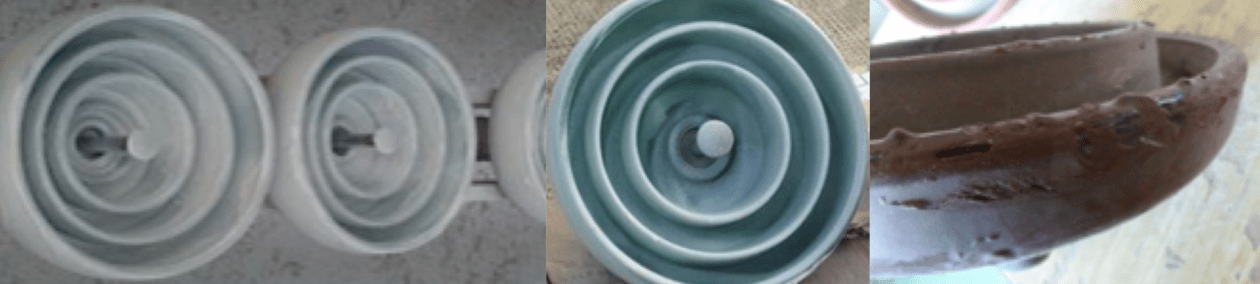
Mostly an issue of aesthetics, this is also an indication of potential problems in consistency of coating deposition. Fig. 9 shows examples of undesirable aspects, which include runs, droplets or absence of coating in certain areas.
Adherence
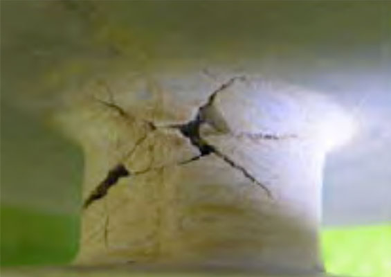
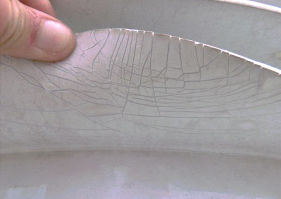
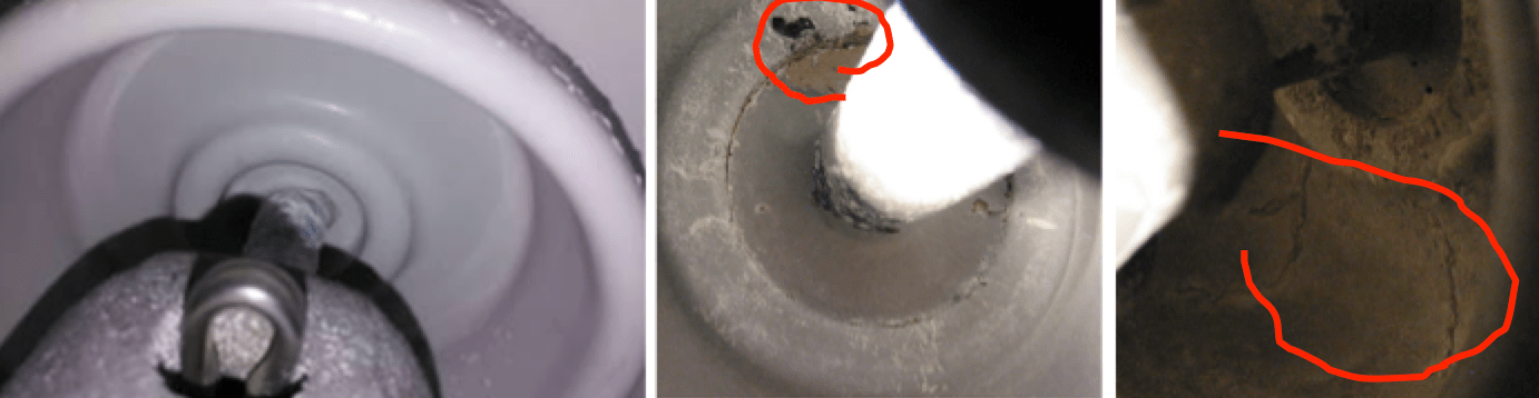
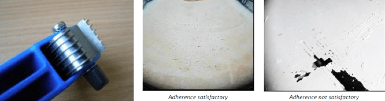
Optimal adherence of a coating requires appropriate preparation of the insulator surface beforehand and optimal cleanliness is achieved in an industrial environment. Fig. 10 shows what can happen to a coating if applied on-site without proper care to prepare surfaces before application.

While coating applicators chose their own process to achieve this goal, what matters to end users is having some sample test to verify consistency of adherence during application. Two methodologies exist in this regard: the scratch test as per EN-ISO 2409 and the boiling water test. The first is easy to perform without need for laboratory equipment since it relies on only a special fork designed for this standard (see Fig. 11). Adherence is considered acceptable if the scratch does not peel the coating but rather cuts through its thickness.
The boiling water test, referred to in IEEE 1523, involves 100h immersion in a tank of boiling water in a laboratory setting and therefore cannot be easily performed as a sample test. Adherence is verified at the end of the test. Apart from this procedure not explaining the time between extraction from the water and the peeling test, it also ignores the fact that silicone is permeable to water and especially water vapor. While this test can serve to evaluate interfaces on composite insulators, it does not take into consideration that thinness of coatings will allow water to easily permeate below the coating. Therefore, this test makes sense only if there is sufficient time to let the coated insulator dry. If a coating is properly applied, adherence can be verified after a rest time of approximately 24h to 48h. Fig. 12 shows examples of temporary inhibition of adherence with samples from a variety of coating suppliers. This test, which could be adapted as a type test, is not suited to the needs of sample testing.


Thickness
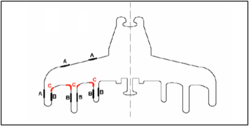
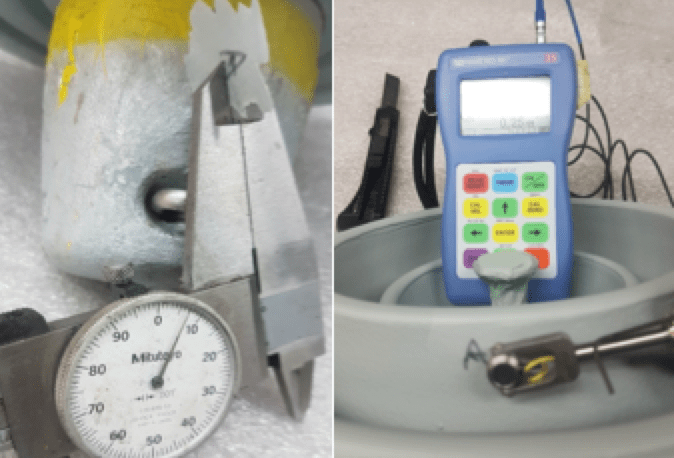
Excess thickness does not necessarily equate to good adherence while not enough coating can result in areas left uncoated. There is consensus around typical optimal thickness values, supported by decades of field experience. These values should therefore be considered as a reference. While thickness cannot be accurately measured at the bottom of insulators between ribs, there are recommended guidelines for the top surface or along the ribs themselves (as in Fig. 13). Measurements should be made on a dry surface using a traditional caliper and an electronic film thickness device (see Fig. 14). Thickness measurements must be performed at 9 different positions (3 x 3 points at 120° apart) on the top surface of the skirt (A) and 15 positions (3 x 5 points at 120° apart) on the ribs (B). Area C is not practical for taking measurements.

Fully or Half Coating Insulators
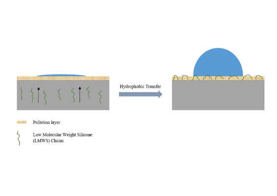
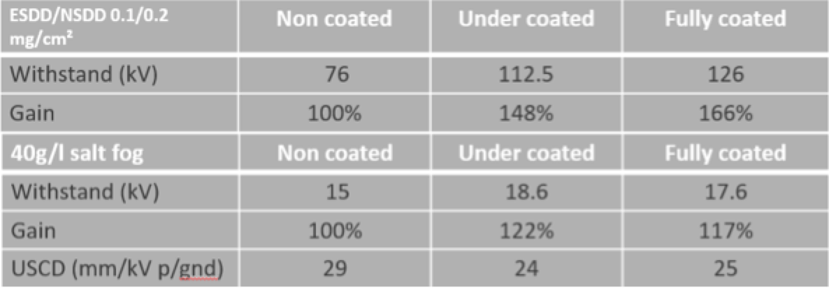
Research conducted 20 years ago suggested that enhanced pollution performance of under-coated insulators (see Fig. 15) makes this an interesting alternative to fully coated insulators, which are more difficult to pack, ship and handle. Yet this finding did not result in large scale application until about 10 years ago, when Sediver began research into expected performance of under coated insulators. These days, this option has become increasingly popular among utilities whose overhead lines face severe pollution.
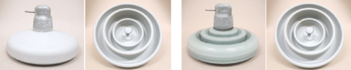
Pollution performance tests on silicone require special attention given the dynamic behaviour of a hydrophobic surface. Since pre-conditioning can temporarily destroy this property, quick or rapid flashover testing is preferable, with an additional withstand test for verification. In this context, extensive testing compared fully and under-coated glass insulators and these tests were cross checked at independent laboratories. Fig. 16 shows results in salt fog and under solid layer pollution conditions and the performance of both designs appears comparable. Under-coating therefore appears an interesting alternative.
Recommendations
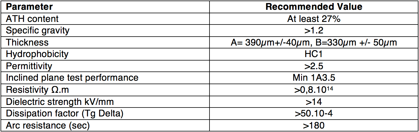
The parameters described above provide comprehensive information when selecting and testing silicone coated insulators. Moreover, the following tables can serve as guidelines for type tests and sample tests. Reference values are proposed based on combined laboratory and field experience covering more than 20 years.
Type Tests
The following can be considered as reference for type tests:
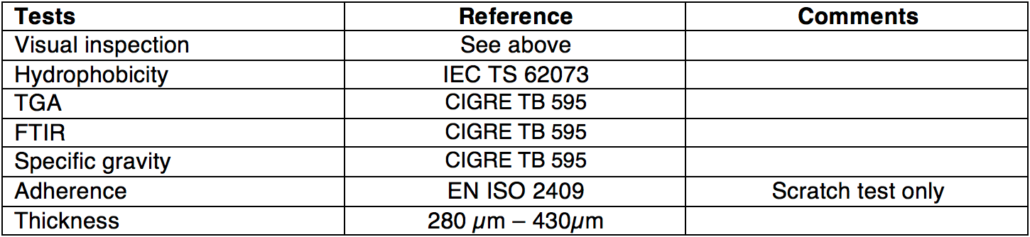
Sample Tests
The following tests can serve as sample tests, with sampling size E1+E2 as per IEC 60383 and similar re-testing conditions.
Reference Values