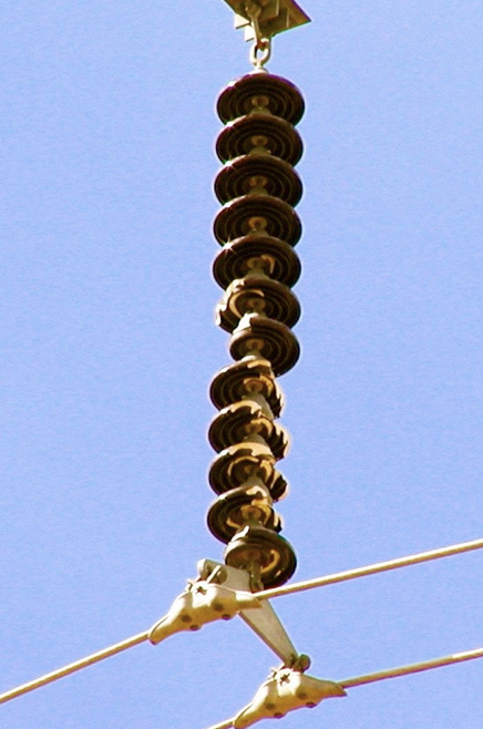
In cap & pin type suspension insulators, the electrodes are separated by only about 2.5 cm of porcelain, subjecting the dielectric to considerable electrical stress. The failure mode of interest in this design is therefore puncture rather than surface flashover. Punctured units can lead to dropped conductors as well as decreased life for the remainder of the string since the remaining healthy units are subjected to greater than normal electrical stress. By contrast, puncture is far less likely in insulator configurations such as line posts or long-rods since voltage being is applied across a much larger porcelain dielectric.
While most users tend to think of porcelain suspension insulators as a single class of homogeneous products, past research showed that large variations in quality are possible due to differences in microstructure.

Porcelain insulators must pass standards such as ANSI C 29.1 or IEC 60383 before they can be considered for installation on overhead networks. However the tests described in these standards were not intended to compare products from different suppliers. Nor do these tests provide information on how long insulators can be expected to last in service. Instead, this type of knowledge is obtained only through service experience. For example, while there are many instances where certain porcelain suspension insulators have performed well for over 50 years, others have been known to fail in a relatively short timeframe, e.g. from 5 to 20 years.
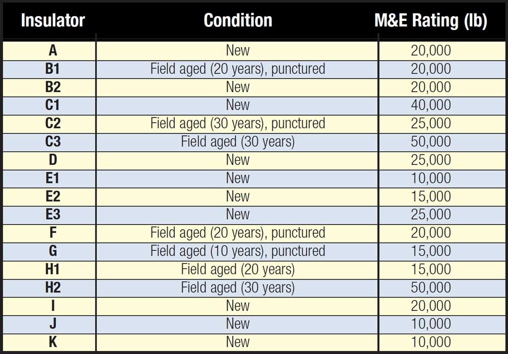
As part of the research, new porcelain suspension insulators from different manufacturers were assembled from utility inventories. In addition, a number of this type of insulators were removed from lines following 10 to 30 years service. Some of these were found to have already been punctured. Table 1 lists the insulators studied with those identified by the same letter coming from the same manufacturer.

Materials & Manufacturing of Wet Process Porcelain
To better appreciate the role played by porcelain microstructure on both electrical and mechanical performance, Fig. 1 offers a synopsis of the manufacturing details for such insulators. Porcelain is a mixture of clay, quartz and feldspar. In the case of distribution class insulators, it is common to use siliceous (quartz) porcelain, whereas aluminous (corundum) and cristobalite porcelain are used for higher strengths, as required for transmission voltages. These minerals are mined all over the globe and, since no two locations are alike in every respect, some variations can be expected. These variations must then be considered during subsequent manufacturing processes such as mixing and firing to ensure consistent quality of the final product.
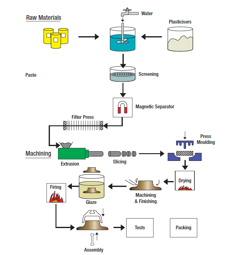
Raw materials are mixed in water to form a slurry. Water facilitates
intimate blending of the various constituents and helps shaping the product into its final form. Moisture is then removed in various stages of forced drying. Particle size of ingredients is one of the parameters that can greatly influence insulator performance and is commonly expressed as a mesh number: the higher the mesh number, the smaller the particle size. High voltage porcelain insulators use much greater mesh numbers (i.e. 325 or higher) than porcelain intended for non-electrical applications. For example, it is quite common to use mesh numbers of only 150 (106 µm) for applications such as dinnerware, sanitary ware or floor tiles.
Firing takes place in shuttle kilns or in long tunnel kilns where temperature cycle is controlled through the different zones with the maximum being in the range of 1150-1250°C. There are variations in energy source used for heating the kilns, e.g. oil, gas, and electric but natural gas is perhaps the most common these days. Metal hardware (i.e. the cap and pin) are cemented onto the porcelain shell with some manufacturers using Portland cement while others use a mortar mix (Portland cement plus silica filler).

Evaluation Methods for Insulators Being Tested
1. Visual
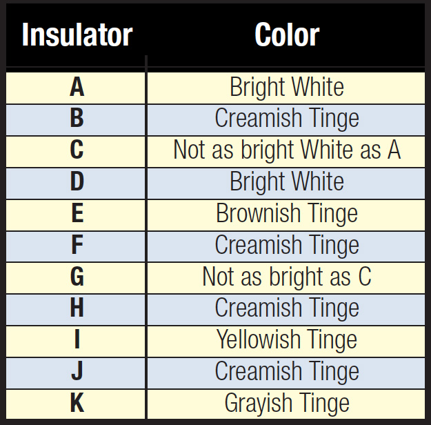
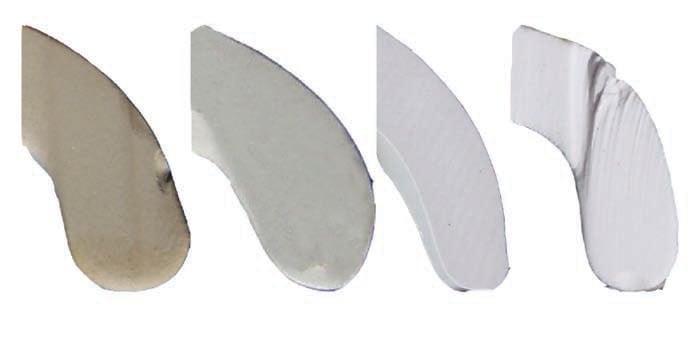
The insulators being tested were first cut axially using a high pressure water jet in order to expose their cross-section. Details such as the color of the porcelain body, uniformity of cement-porcelain interface and presence of large pores, if any, were noted. Table 2 and Fig. 2 show that there were sometimes large variations in color of the porcelain body. Deviations from bright white suggest presence of impurities and/or inadequate oxygen during the firing process.

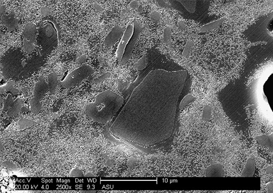
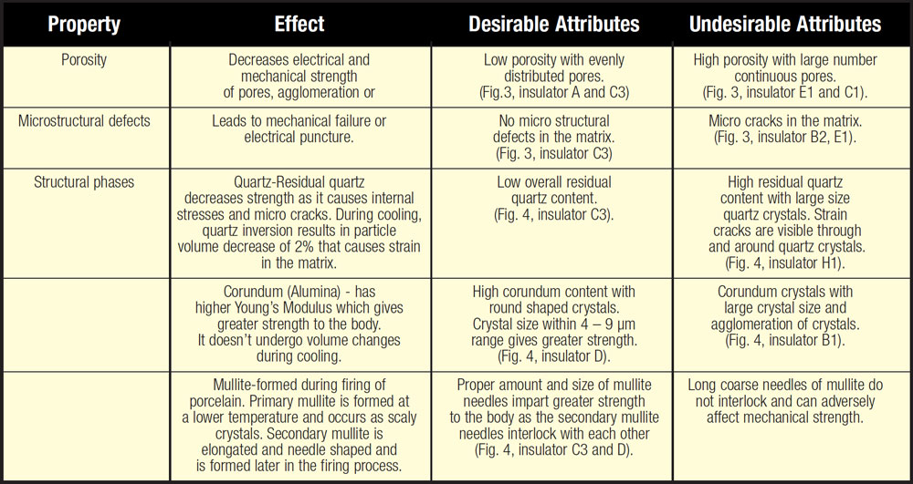
Important material characteristics of the porcelain body include porosity, microstructural defects, crystalline phases and size. These properties were evaluated by scanning electron microscope (SEM) and Table 3 summarizes their impact on insulator performance.
Chief Sources of Information: [1]. W. M. Carty and B. M. Pinto, “Effect of Filler Size and Strength of Porcelain Bodies”, Ceramic Engineering Science Proceedings, Vol. 23, No. 2, pp. 95-105, 2002.[2]. J. Liebermann, “Microstructure Properties and Product Quality of Strength-Stressed High-Voltage Insulators”, American Ceramic Society Bulletin, Vol. 82, No. 2, pp. 39-46, 2003.
2. Scanning Electron Microscopy
The following steps describe the preparation of samples:
1. Small pieces were obtained from the insulator using a diamond saw;
2. Samples were polished using 800 grid sand paper, 6 µm and 1 µm diamond films;
3. Samples were then cleaned in an ultrasonic bath with acetone;
4. Samples were etched with 20% HF acid for 10 seconds to expose grain boundaries;
5. Gold coating was done on polished and etched samples using gold sputter coater for 3 minutes.
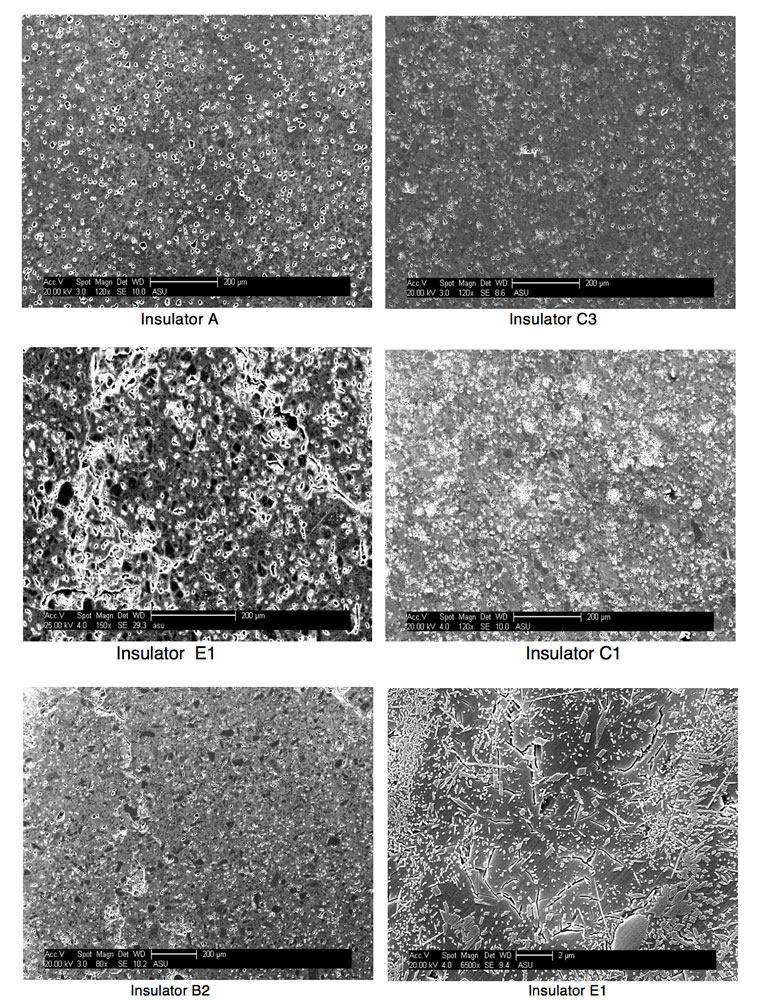
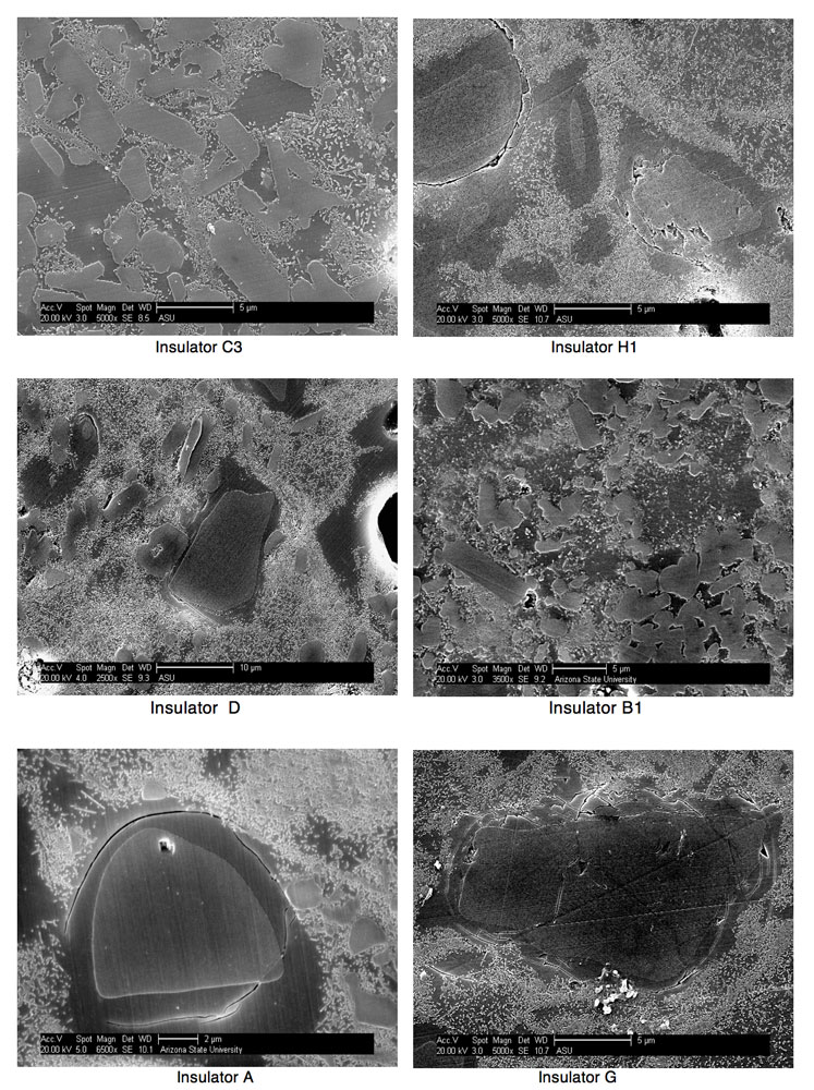
A Philips XL-30 SEM was used to obtain images, the most significant of which examples (good as well as bad) are shown in Figs. 3 and 4. Fig. 3 shows examples of porosity and microdefects and Fig. 4 shows structural phases in porcelain. Table 3 refers to these figures.

3. X-ray Diffraction (XRD)
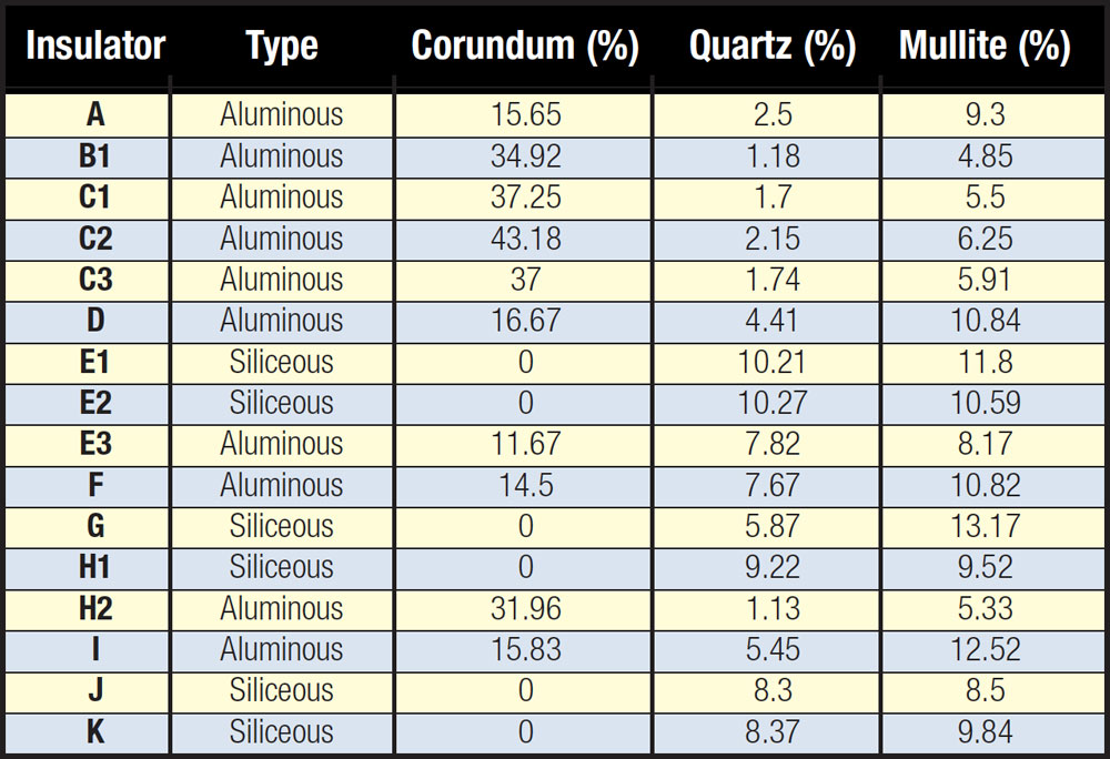
XRD analysis was done to quantify the phases present in different porcelain insulators. The Internal Standard Method was used with calcium fluoride as the standard. Calibration data was first developed using pure quartz, corundum and mullite. A small piece of the insulator was finely powdered in an agate mortar and pestle and mixed in a known ratio with calcium fluoride. X-ray powder diffraction was then done using a Siemens D500 diffractometer.
Table 4 shows the different phases present in the insulators evaluated. Low strength siliceous porcelain insulators do not have any corundum. It is interesting to note that the corundum content was variable among the high strength aluminous porcelain insulators evaluated.
Summary
Punctured insulators removed from service had the following features: agglomeration of corundum crystals (see Fig. 4, insulator B1), long running micro cracks (as in Fig. 3, insulator E1), large quartz crystals (> 60-110 µm) and agglomerates of pores. Insulators that had not failed had well dispersed and relatively few pores.
This past research demonstrated that there can be significant variations in the microstructure of porcelain suspension insulators. Other factors that determine performance in service are cement composition and operating conditions including line voltage, position of the unit in the string and lightning severity. Existing standards for porcelain insulators help to specify minimum requirements but tighter specifications are desirable to ensure high reliability and long life of insulators, especially on EHV and UHV transmission lines.