What do you do when right-of-way restrictions make upgrading an existing 125 kV transmission line to 400 kV impossible using traditional design? That was the challenge facing engineers at a Swiss power supplier. Years ago, INMR visited Energie Ouest Suisse (now Alpiq) to see how this challenge was overcome using a novel compact line that became the world’s first such application at 400 kV. Such experience is particularly relevant these days given that finding corridors for new power lines or expanding existing line corridors to accommodate upgrades is either impossible or could involve years of negotiations.

Across most of Europe, the average time required to complete a new overhead transmission line project is now estimated at well over 10 years. Moreover, the majority of this time frame is devoted to overcoming public objections and obtaining all necessary approvals. This situation particularly applies to Switzerland, where environmental and other restrictions on new or expanded line corridors have been part of the electricity supply landscape for decades. It was against this background that engineers faced a daunting challenge to successfully complete the upgrade of an old double circuit 125 kV line running between the cities of Geneva and Lausanne. The line passed through rural areas with relatively high population density. Given land costs, it was not seen as economically feasible to enlarge the existing right-of-way of 9.5 m on either side to meet requirements of a conventional 400 kV line where some 15 m would typically be needed to each side.
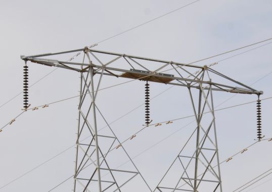
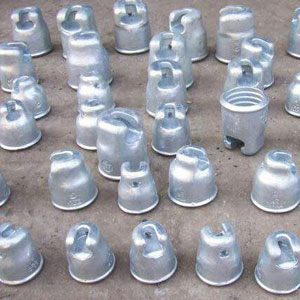
The project aimed to convert the existing line to two 400 kV circuits, while also maintaining a single phase 132 kV railway feeder circuit on the same structures. In order to deal with these constraints, a short section of line had to be designed as a compact 400 kV line. This was accomplished using insulated cross-arms made up of standard composite tension insulators as well as 3 m hollow core composite insulators with 143 mm external diameters.
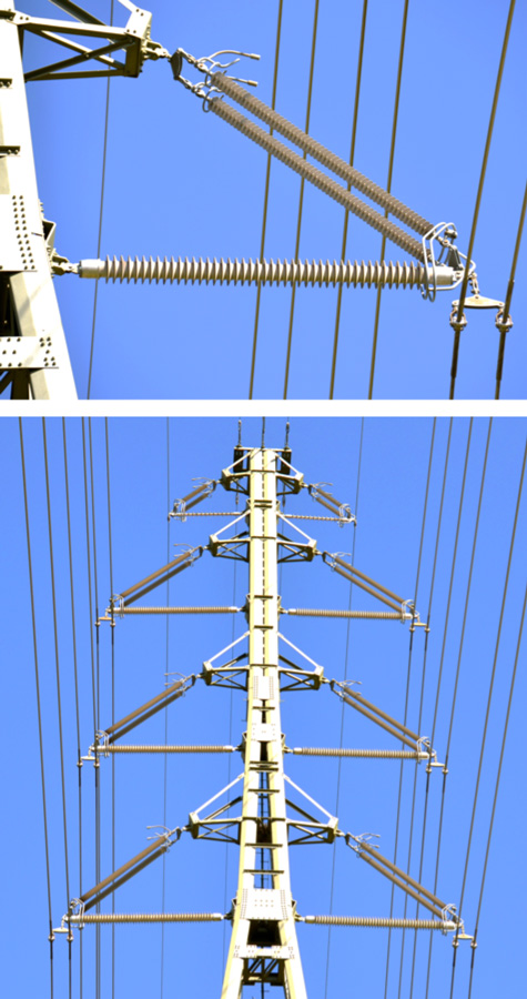
The rationale for specifying a hollow core insulator for the strut application related to the high compression forces from heavy 40 mm conductors operating where loads under critical wind and icing conditions exceeded the maximum 55 kN for the 76 mm diameter solid core composite insulators supplied 20 years ago. While porcelain insulators in such a horizontal Vee configuration presented an option, engineers were concerned that these would be too heavy. Because of required clearances of 3 m, a porcelain insulator of such length that could handle the required compression loads would be too large to be practical. It also would not solve the dynamic requirements associated with the types of towers selected, which employ a pivoting cross-arm assembly. Had a fixed arrangement been used, an even larger cross-section would have been necessary to take the loads.
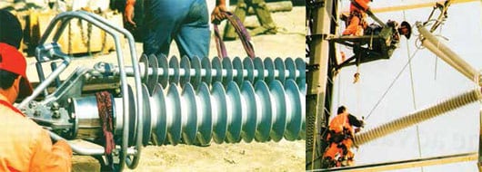
According to the Swiss-based supplier of the insulators used on this project, one of the benefits of this design was being able to assemble complete cross-arms on the ground and then lift them into place. This reduced installation time for each to about 10 minutes and therefore only about two-hours were needed to completely install all cross-arms on every tower.

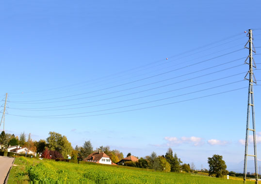
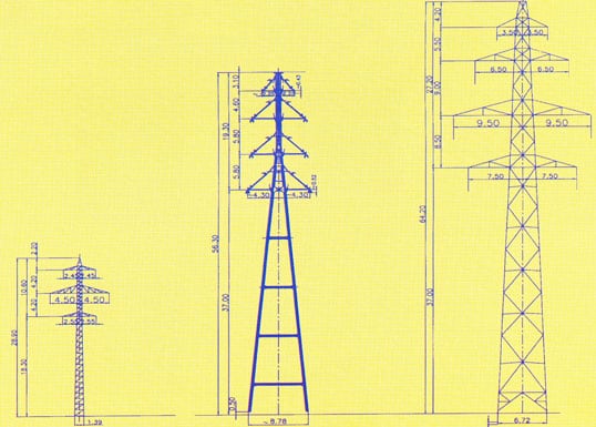
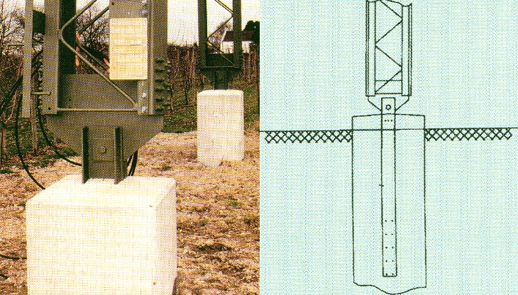
The special towers selected for the short section of compact line were bi-dimensional articulated towers supported at the tops by the ground wire as well as the conductors attached to them through the pivoting cross-arm arrangement. Articulation of the towers was deemed necessary in order to meet Swiss norms for a mobile system. These 56 m structures each weigh about 15 tons and were developed in Italy as the largest version in a family of towers used for 130/150 kV compact line applications. In addition to offering a solution to the low environmental impact requirement of the affected area, the towers also provided benefits by reducing typical foundation costs for the heavier, self-supporting lattice type structures used elsewhere on the line. The height requirement of the towers was dictated by the need to maintain exactly the same electromagnetic field as existed with the previous 125 kV line.
Each tower was eventually between 20 and 25 percent more costly than a conventional lattice type design, due mainly to the fact that their engineering and testing costs that had to be absorbed by only a handful of these units. However, once this work had been accomplished, using these same structures on a completely new line would likely be comparable to the cost of a conventional line. Still, without the new towers and design for this application, any alternative solution would have proven far most costly.
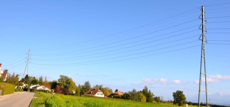
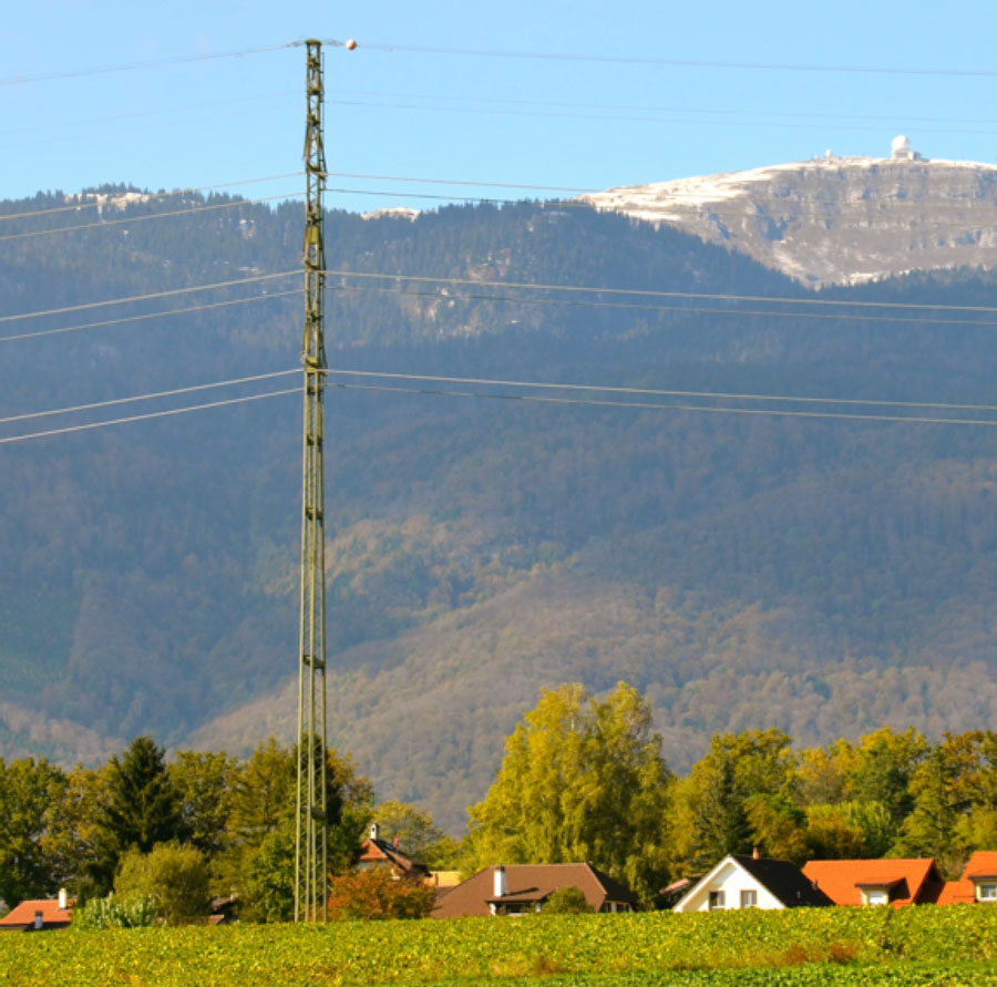
Looking back on the achievements of this upgrade project, some general conclusions apply equally well to the present day. One of the objectives, given the difficulty in building new lines in Switzerland, was to streamline towers and make them more aesthetic. In this regard, composite insulators offered real benefits. For example, by using them, weight of cold-formed steel towers was lightened by about 20 percent. Equally important, total number of structural members was reduced by up to 40 percent. All this allowed the line’s towers to better blend into the surrounding countryside.