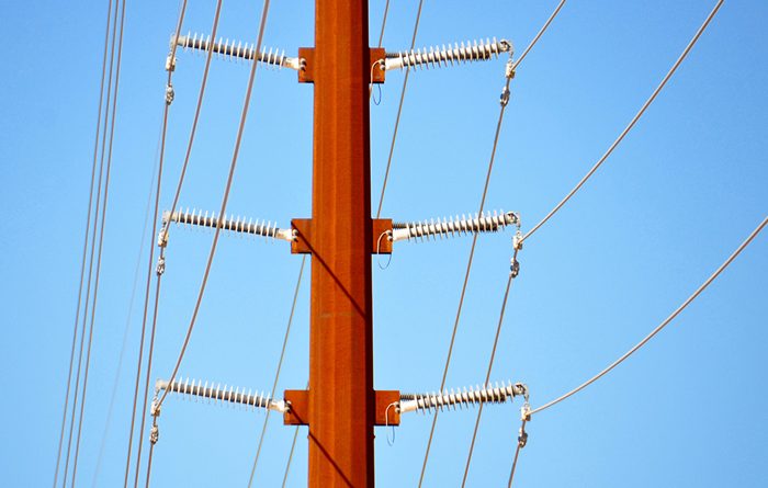
Line post type high voltage insulators have been used to support and insulate overhead electric lines for over 70 years. First introduced at the distribution voltage level, their use was soon extended to transmission lines to realize the full potential to reduce the cost of new lines, in particular, by lowering structure costs, and reducing right-of-way widths (Fig. 1).
Up to about 30 years ago porcelain line posts were the only choice available to line designers, which gave reasonably good service, except in those cases where the brittle nature of porcelain led to catastrophic cascade line failures [2],[3].
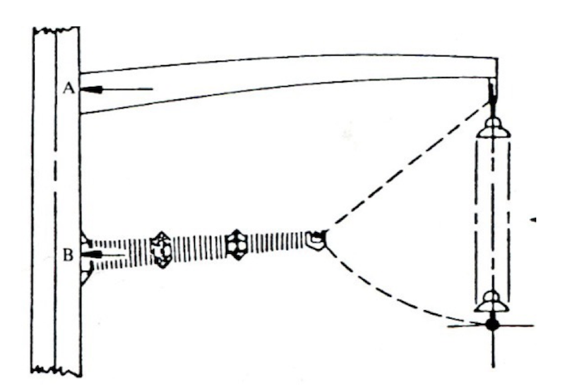
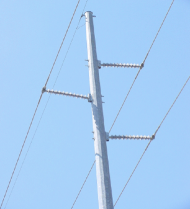
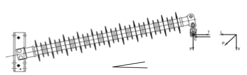
Composite line posts are more flexible compared to porcelain line posts and, when they became available, quickly became the insulator of choice for this type of application (Fig.2). But this increased flexibility results in a deflection of the composite post due to service loads which must be considered for their proper use (Fig. 3).
Combined loading tests, in particular ultimate strength tests, are difficult to perform because the applied loads, which can cause large deflections, must be maintained perpendicular with the axial plane of symmetry for the post throughout the entire test. The necessary complexity of pulling test rigs, and the great variety of possible load combinations, encourages the use of analytic techniques for providing guidance on combined loading of composite line posts. In addition users are most interested in “application curves” which show combinations of in-service loads that can be accommodated in service.
Recommendations with respect to individual load combinations are usually provided by manufacturers in the form of combined loading curves to prevent unintentional over loading of the insulators. Unfortunately, lack of uniformity among manufactures in constructing these curves has led to some confusion among users and developing a common recommendation for composite line posts has been problematic. IEEE WG on Insulators formed a TF to address this issue and the status of this work is summarized in this edited contribution to INMR by the late Anthony Baker, retired from K-Line Insulators.

Combined Loading Analysis
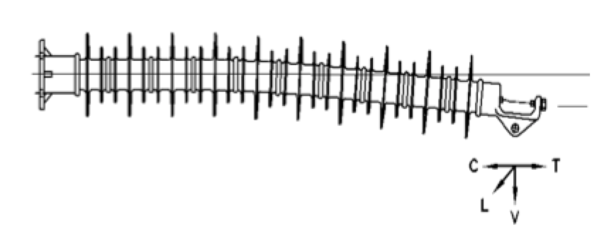
The combined loading problem can be described with the help of Fig. 4. Here the fiberglass rod is shown as a horizontally mounted beam deflected through a vertical distance δ as the result of simultaneously applied loads; V (vertical load), L (longitudinal), and C or T (transverse loads).
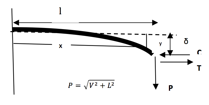
Vertical loads includes the conductor weight and its associated hardware along with any ice covering, longitudinal loads are the result of any unbalance in the horizontal tensions in adjoining span, and the transverse loads result from either wind loads or line angle loads, or both.
The beam, if it is made of an effectively homogeneous material with a uniform cross-section, and a flexural rigidity EI, if it’s not deflected too much (, has a deflection curve given by [4].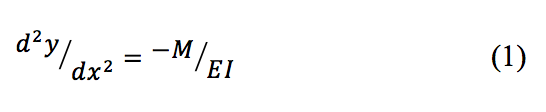
Solving (l) for the deflection as a function of the applied loads allows for the determination of the total bending moment applied at the base of the beam. To satisfy the deflection limit, and user’s desire for application curves, this moment is limited by the Maximum Design Cantilever Load (MDCL) rating for the post insulator and its effective length (ι)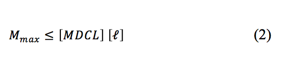
The effective length is the distance from the conductor support point to the top of the rigid base fitting (Fig. 4).
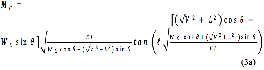
Composite line posts are commonly installed at an inclined angle θ (Fig.5) and the most general expression for the maximum allowed bending moments in terms of the applied loads are:
For the case where the transverse load is a wind load WC in a direction toward the support structure:
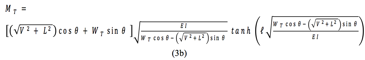
 For the case where the transverse load is a wind load WT in a direction away from the support structure:

Common Model
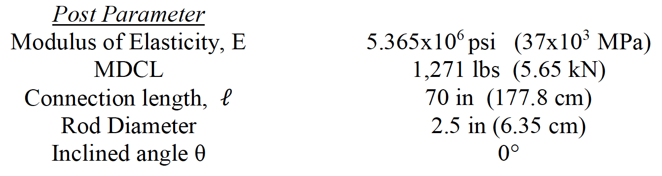
The TF selected a common model composite line post as defined in Table I and asked each manufacturer represented on the TF to provide a combined loading curve for it.
Each manufacturer used their preferred method of making combined loading curves; some used the analysis outlined here, some a FEM approach, and some an undisclosed proprietary method. As was found for a previous CIGRE sponsored project, all the submitted results were in close agreement, validating the analysis presented here [5].
For the θ = 0° case, (3a) and 3(b) reduce to:
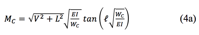
and
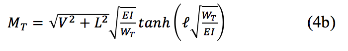 and the combined loading curves for the composite line post defined in Table I according to(4a) and(4 b) are given in Fig.6.
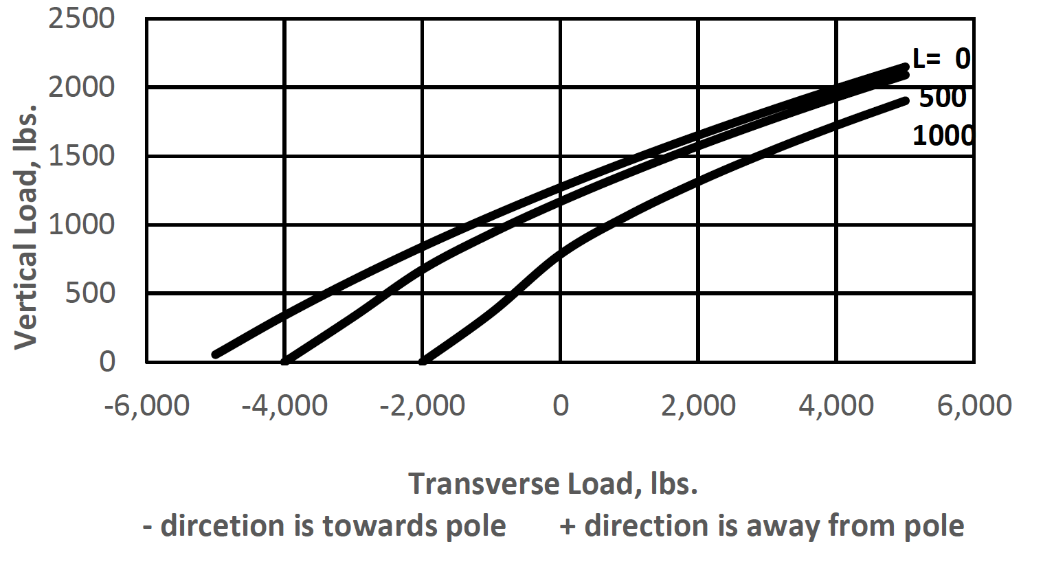
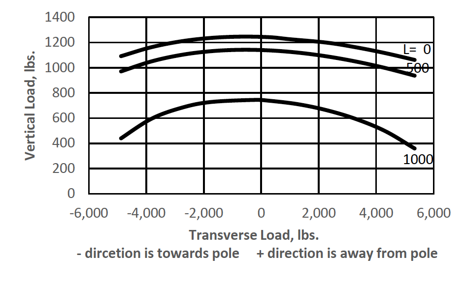
It is interesting to note that according to Fig. 6, since the vertical component of a transverse load in a direction away from the support structure counteracts the vertical weight load, it appears that there is a significant increase in the vertical load carrying capacity of the line post. However, if the transverse load is a wind load, the increased load carrying capacity can’t be realized and Fig. 6 should be corrected as shown in Fig. 7.
As previously noted, composite line posts are commonly installed at an inclined angle to the horizontal and typical angles are in the range 12° to 15°. The combined loading curves for the common model line post defined in Table I except installed at an angle θ = 12° are given in Fig. 8.
Figures 6 and 8 show a significant effect on the combined loading curves for a post installed at an inclined angle (Fig. 5) compared to one installed horizontally (Fig.3).
In addition to the installation angle θ, line angles can also have a very significant effect on the combined loading curves for a particular application. The effect can be positive or negative depending on whether the angles are inside-angles or outside-angles. This concern has not yet been addressed by the TF. Certainly the question is application sensitive and may not lend itself to inclusion in a general recommendation.
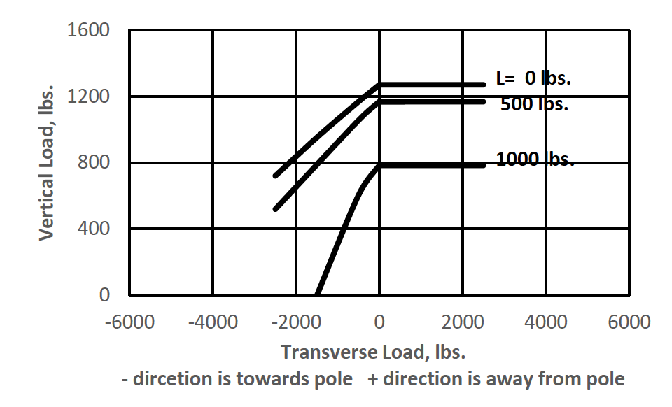
Typical Composite line post end fittings are a ridged base and either a horizontal clamp top (Fig.3) or an eye type (Fig. 5) line-end fitting and the strength of these also have an impact on the combined loading curves for a particular post insulator. The line end fittings have a lower strength than the base fitting but it is usual to assign a single value for the tension/compression strength of a post so it is the strength of line end fittings which governs. The typical clamp top fitting has an ultimate strength rating of ±5,000 lbs. and the eye type fittings ± 15,000 lbs. Each has maximum allowed working strength of 50% of ultimate.
If the Common Model post insulator is considered to have a horizontal clamp top line end fitting, a reasonable modification for Fig. 7 to show the limitation imposed on the combined loading curve accounting for the allowed working strength of the end fitting is shown in Fig. 9.
The effect of end fitting strength on the combined loading curves for particular composite line posts also has yet to be addressed by the TF.

Combined Load Specifications
The TF effort to date indicates that a general recommendation for providing combined loading curves for composite line posts insulators should be feasible but some work remains to be done.
In the meantime the following tentative guidelines may be helpful to users in specifying composite line posts for their particular applications.
• General combined loading curves for composite line post insulators should provide for maximum allowed combinations of service loads.
• It is helpful if typical service loads can be directly entered into the equations to determine combined loading limitations for a specific line post.
• Ultimate strength tests under combined loading conditions require expensive tests to conduct with respect to both facilities and time.
• Application combined loading curves based on (1) are consistent among various suppliers and lead to maintaining a maximum service loading of the post insulator at MDCL or less.
• The installation angle θ has a significant effect on combined loading curves.
• Line angles have a significant effect on combined loading curves and should be treated as special cases.
• The effect of end fitting strength should be included in combined loading curves.
References
1. C. Pohlman, T.A. Pinkham, and A.C. Baker, “A look at compacting transmission lines using armless construction under today’s constraints” , CIGRE paper S33-91 presented at the Symposium Leningrad, USSR 1991.
2. T. Burnham, P.S. Givens, and T.M. Grisham, “High strength polymer post insulators enable economical transmission lines with low environmental impact”, presented at the IEEE Transmission and Distribution Chicago, IL 1994, Paper No. 0-7803-1883-8.
3. A. Cherney and C. Altomare, “Failures of porcelain line post insulators on the Ontario Hydro distribution system” presented at the Canadian Electrical Association Spring Meeting, March 1988.
4. Timoshenko and D.H. Young, Elements of Strength of Materials. New York; D. Van Nostrand Co. 4th Edition 1962.
5. Working Group 22.03, “Guide for the evaluation of composite line post insulators subjected to combined mechanical loads”, Electra, 205, August 2002.