Pollution has had an important impact on selection of insulators installed across the transmission network of Spanish TSO, Red Eléctrica (now redeia). This edited past contribution to INMR article by Elena Nogueroles, Ignacio Serrano, Andrés Pérez and Daniel Blanco reported on strategies used to resolve pollution flashover and increase service life of affected insulators
Between 1985 and 1995, Red Eléctrica used primarily glass insulation on its the overhead transmission network, with small number of lines equipped with porcelain Clevis type insulators. Major insulation problems included high maintenance costs due to the cost of annual washing, especially along the Mediterranean coastline. In spite of this, there was still a high frequency of line faults.

Composite Insulator Strategy
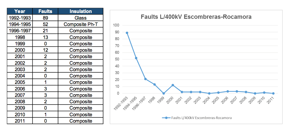
In 1994, Red Eléctrica first began to test application of composite insulation in its 400 kV Escombreras-Rocamora line, one of the worst in terms of frequency of faults. The result was that the frequency of faults was dramatically reduced.
Due to these positive results, starting 1995 the same composite insulators were installed 50 km inland from the Mediterranean and South Atlantic coastline. Then, in 2010, Red Eléctrica included recently acquired circuits in the Canary and Balearic Islands in this composite installation strategy.
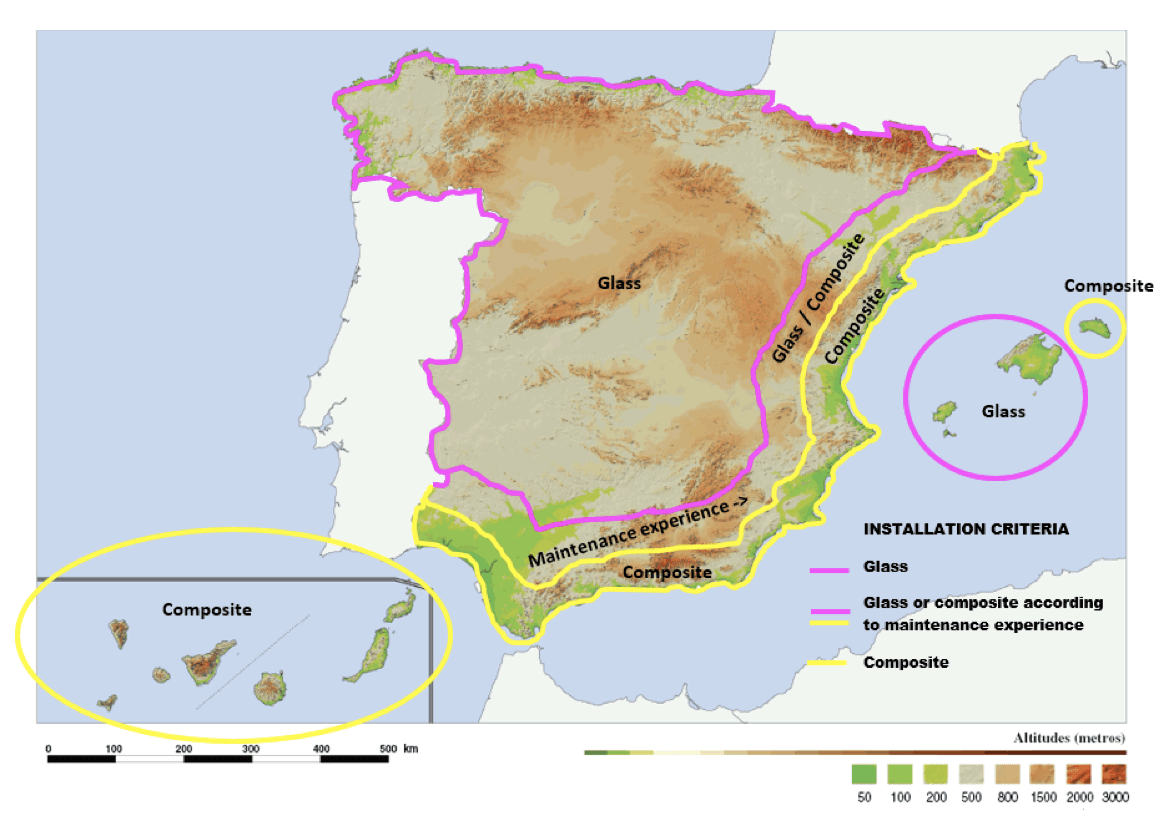
Along 50-100 km inland South Atlantic and Mediterranean coast, Red Eléctrica proceeded to install either glass or composite insulators, based on related maintenance experience over the years.
However, among the issues discovered were:
1. Degradation of the insulator housing due to erosion in heavy pollution areas.
2. High cost of routine inspection on these insulators to detect degradation prior to complete failure of the insulation
Silicone-Coated Glass Insulator Strategy
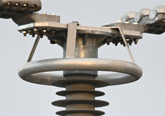
In order to resolve the problem of limited service life of composite insulators operating in special critical pollution zones, in 2009 Red Eléctrica began to install silicone coated glass insulators on 11 circuits within these problem areas. The most representative installation of these silicone-coated glass insulators is shown in Fig. 4.
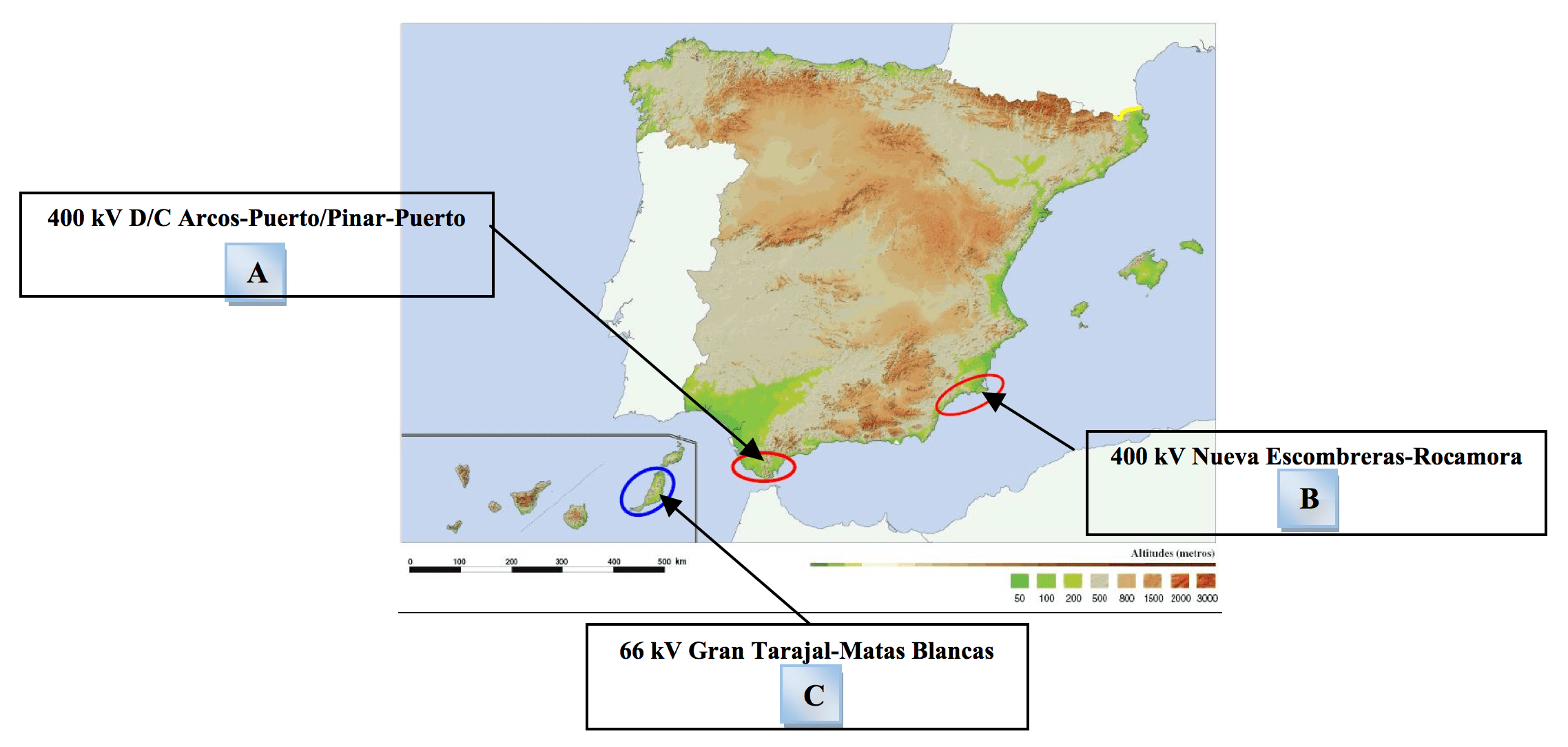
A – 1st Installation
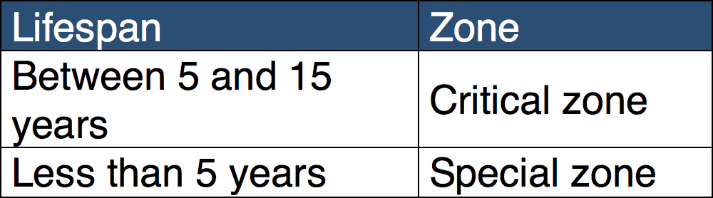
For example, composite insulators on the 400 kV Arcos-Puerto y Pinar-Puerto Line, where their lifespan was only between 1 and 5 years, were replaced with silicone-coated glass insulators.
One decade after the silicone-coated glass was installed, these insulators remained in good condition, with no recorded faults and no maintenance action required.

B – 2nd Installation
In 2013, three different types of insulators were installed on each phase of the 400 kV Nueva Escombreras-Rocamora Line in order to compare the performance of different technologies in the same pollution zone. The three different insulators had the same creepage distance and total length:
• Experimental composite insulation (Composite Class 1).
• Conventional composite insulation (Composite Class 2).
• Silicone-coated glass insulators
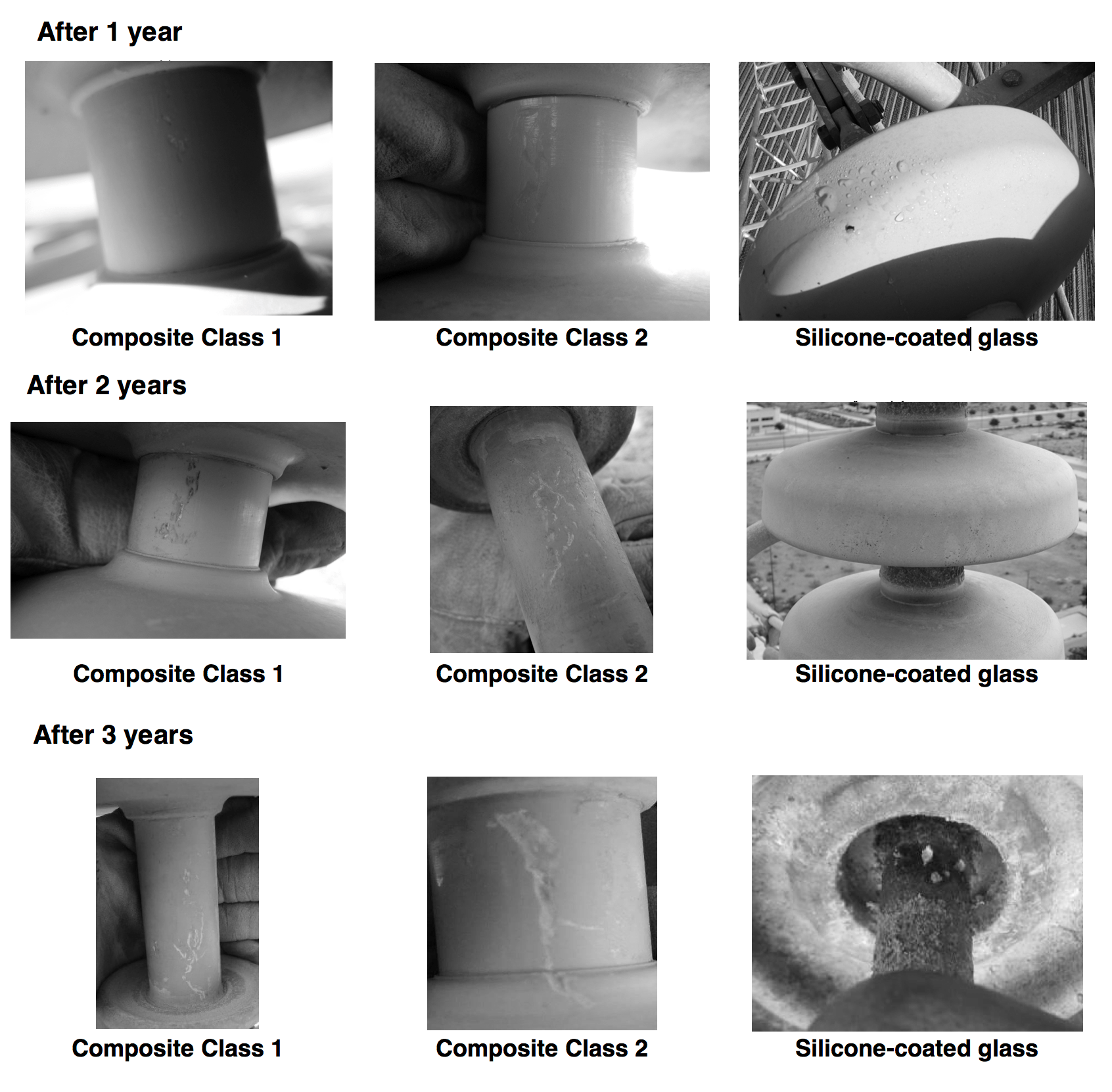
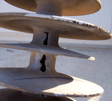
No faults were recorded on the line during the three years since installation of these insulators. In the case of the Class 1 composite insulators, erosion on the housing was detected. More significant and deeper erosion was detected for the Class 2 composite insulators. The silicone-coated glass insulators showed evidence of minor pollution accumulation on the underside of some insulators and some degradation of the silicone coating on the upper side. Nevertheless, there was no significant risk of mechanical failure. Based on this field test, it was concluded that the silicone-coated glass insulation offered superior performance to composite insulators in zones of high pollution.

C – 3rd Installation
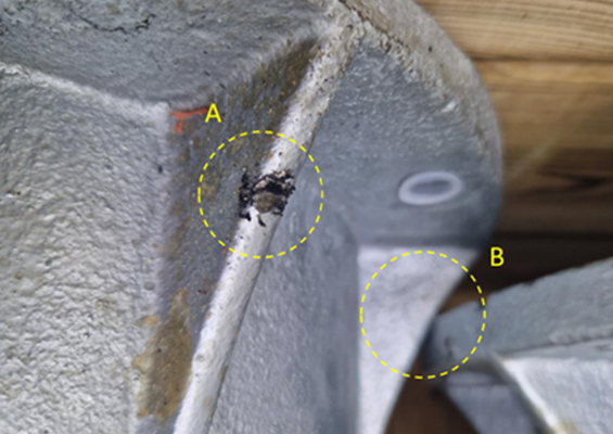
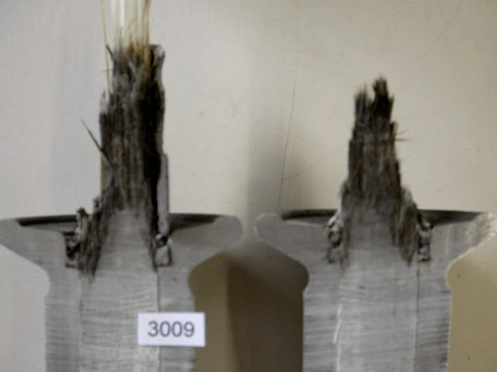
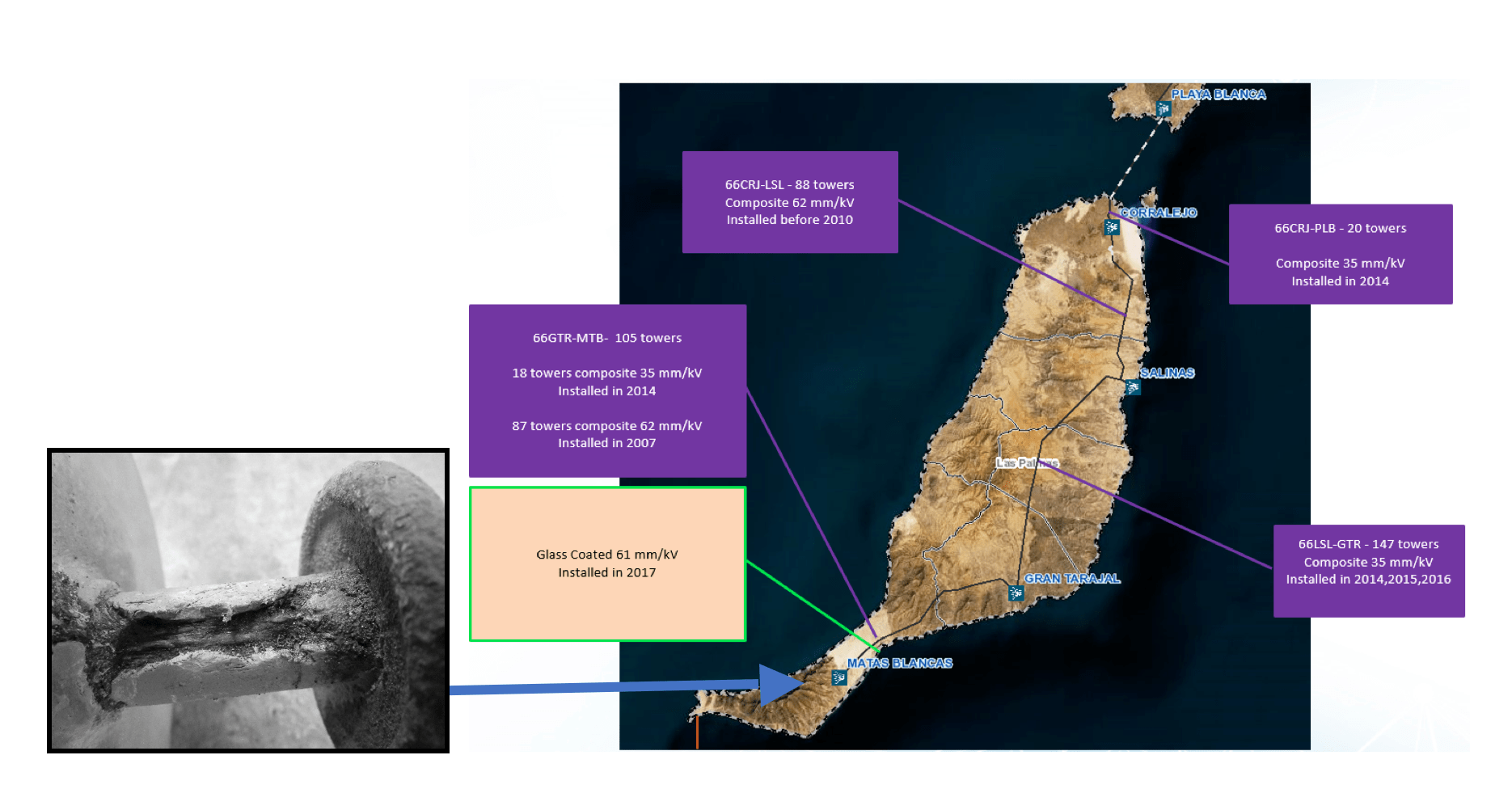
Given this experience, between 2016 and 2017, REE installed silicone-coated glass on its 66 kV Gran Tarajal-Matas Blancas Line, located in Fuerteventura on the Canary Islands. In 2016, there had been a failure of a composite insulator failure on this line that caused a temporary blackout affecting several areas. The failed insulator, first installed in 2013 on tower 84, was found to have suffered serious degradation of the housing with resultant exposure of the core rod and some fiber carbonization.
In Sept. 2016, based on this event, REE developed the following Action Plan:
• Analysis of faults and other incidents on the island’s lines as well as their locations and causes;
• Visual inspection of composite insulators installed on the 66 kV GTR-MTB Line and replacement for coated glass insulators and also visual inspection of composite insulators installed on the 66 kV LSL-GTR line.
• Laboratory testing on some of the composite insulators installed on 66 kV lines, including GTR-MTB, LSL-GTR, CRJ-PLB and CRJ-LSL.
• Survey of manufacturers to establish recommended specific creepage distances, corona ring requirements;
• Analysis of degradation areas and creepage distances used in those areas;
• Determining optimal inspection frequency for composite insulators;
• Revision of internal standards and regulations;
• Elaboration of minimum spare requirements for glass insulator discs;
• Revision of technical qualifications of maintenance personnel conducting line inspections.
Based on this Action plan, Red Eléctrica concluded the following:
1. Cause of failures: Degradation of the core by partial discharges in the zone with high electric gradient with subsequent carbonization of the glass fibers. This is typically associated with very high pollution service environment;
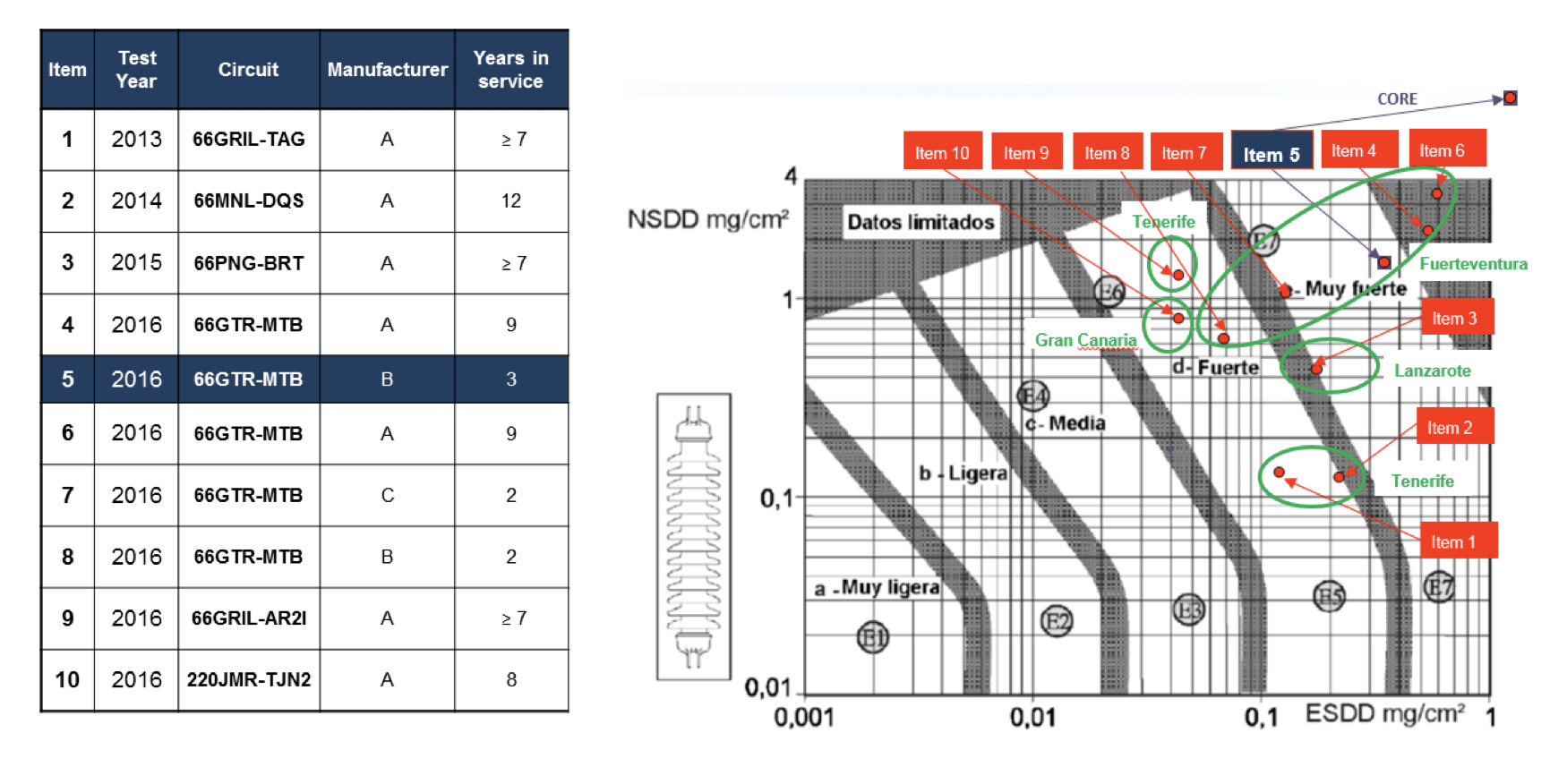
2. Visual inspection of 66 kV LSL-GTR (31mm/kV): insulation installed in 2014-2016 still in good condition;
3. Visual inspection and laboratory testing of 66 kV GTR-MTB (31mm/kV): insulation installed in 2014 on 18 towers now in bad condition with slight degrees of erosion in the silicone housing of 5 insulators and unsatisfactory results during laboratory tests;
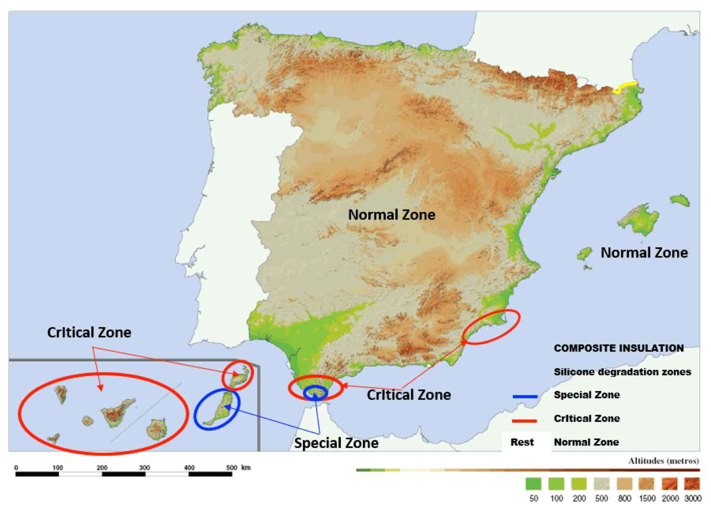
– Level of pollution in Fuerteventura is above that of other Canary Islands.
– Insulators of 35 mm/kV specific creepage with 2 to 3 years of service are now in poor mechanical and electrical condition.
– Insulators having 62 mm/kV specific creepage and with 9 years in service are still in good condition.
4. Survey of manufacturers:
– Corona rings are to be installed in areas of high pollution and voltage < 220 kV.
– Specific creepage distances between 40 and 55 mm/kV are being supplied in countries such as Dubai, Iran, Saudi Arabia, Tunisia and Egypt for both composite and coated glass insulators.
5. There is a need to inspect live-line using a workbench to have a better view of insulators.
6. The terminology ‘Special Degradation Zone’ is to be assigned to Fuerteventura Island, which implies installing only silicone-coated glass.
7. Install on the entire GTR-MTB 66 kV line, silicone-coated glass insulators with specific creepage of 61 mm/kV.

Conclusions
Results obtained during in service performance evaluations indicate that silicone-coated glass insulators are an excellent technical and economic solution to improve the behavior of insulation in areas of high pollution and also to avoid need for periodic cleaning of insulators. Advanced performance is achieved in areas of extreme pollution, combining the hydrophobic properties of silicone coatings with the mechanical reliability of glass insulators. After years of experience, it has been deemed necessary to update the insulation, installation and maintenance policy at Red Eléctrica.
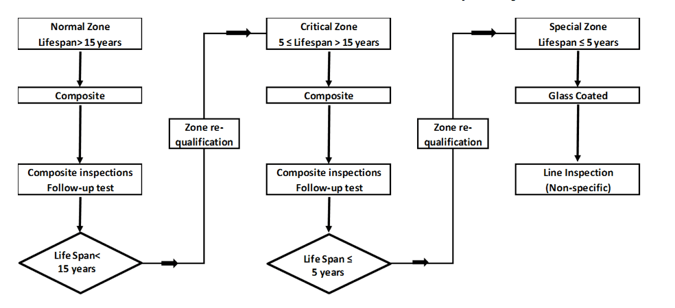
Fig. 10: Composite insulation maintenance policy.
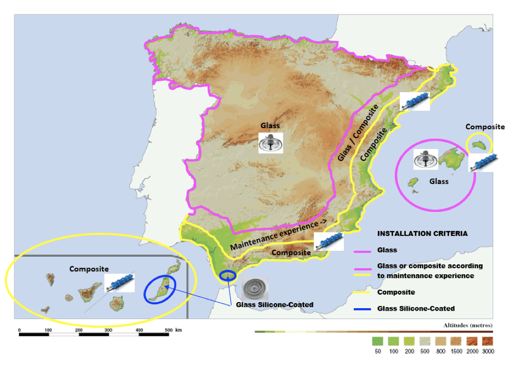
In addition, in order to achieve optimal insulation in each service area, a pollution map of Spain was to be developed according to IEC 60815. This allowed proper selection and design of the best insulation for each zone – something that was especially important in areas of high pollution (based on DDDG and ESDD/NSDD measurements).