While metal oxide surge arresters are comparatively modern devices, they have nonetheless undergone rapid development over the past 30 years. For example, such arresters were among the first apparatus in power systems to be equipped with polymeric insulation. Progress has also been achieved in improving MO resistor performance, making arresters among the most reliable of all system components.
This edited past contribution to INMR by Prof. Volker Hinrichsen, now retired from the Technische Universität Darmstadt in Germany addressed challenges in further development of gapless MO arrester technology.


Background
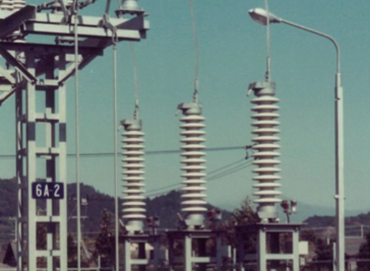
Gapless metal oxide arresters are the byproduct of the ‘accidental’ invention of ZnO resistors in 1968 by Matsushita Electric Industrial in Japan. Subsequent development toward overvoltage protection devices for electrical power systems resulted in the first such application by 1975.
Starting in the mid-1980s in the case of distribution class arresters and by the early 1990s for high-voltage station class arresters, MO arresters became one the first types of electrical apparatus to be equipped with polymeric insulation. This soon became state-of-the-art for distribution and is now also increasingly applied on transmission systems.
Moreover, unlike the gapped silicon carbide arresters it replaced, MO technology has also allowed applications beyond traditional overvoltage protection at substations. These new applications have included multi-column UHV station arresters for systems above 1000 kV, HVDC arresters in converter stations (valve protection arresters being the most important), distribution and transmission line arresters (with or without a series gap) and arrester banks in flexible AC transmission systems for overvoltage protection of series capacitors in case of line faults. The most recent development sees MO arresters applied as indispensable energy absorbers in emerging HVDC circuit breakers.
Energy handling capability and potential electrical degradation of MO resistors has been one of the concerns since the start. Due to permanent connection to the line, a gapless MO arrester can theoretically suffer thermal runaway after excessive energy input or due to deterioration of its non-linear voltage-current characteristic. Fortunately, electrical degradation is no longer regarded as a risk for experienced arrester manufacturers. Moreover, demanding test requirements in current standards will hopefully avoid any setback from this high level already achieved.
However, today’s less conventional applications require different approaches when specifying and verifying energy handling capability than only looking at line discharge, as was previously the case for station class arresters. Supported by work at Cigré, test standards have now been improved to cover all aspects of modern-day arrester applications, though more still has to be done. At the same time, IEC and IEEE arrester test standards are now being harmonized, ultimately resulting in a project for a dual logo standard on all types of line arresters – as prepared by a joint IEC and IEEE WG (Project IEC/IEEE 60099-11).
One of the most interesting developments these days is that simulation tools have become very powerful. This has made it possible to optimize EHV and UHV arrester designs with respect to external grading system and thermal stability limit using non-linear, fully coupled electro-thermal simulations. This, in turn, has opened the door to designing UHV arresters with reduced need for full-scale laboratory testing, which is difficult at these voltage levels. The trend to avoid full scale testing is also supported by ‘smart’ approaches in the standards in regard to dielectric withstand tests. For example, based on sufficient experimental experience, the need for such tests can be avoided if certain minimum clearance requirements are fulfilled. Thus, UHV arresters can be developed and qualified without need for full-size 1000 kV test facilities.

Energy Handling Capability
Surge arresters act to limit overvoltages caused by transient lightning or switching phenomena. At the same time, they must avoid tripping of a line. In that latter role they do not need to limit the voltage to zero but rather to a level that can be safely withstood by apparatus in the system. This means that arresters must be able to dissipate power during passage of a current to ground and, consequently, absorb energy. Some energy handling capability must therefore be specified for an arrester. Historically, this was done in different ways for station and for distribution class arresters.
The most challenging duty for station class arresters was considered a line discharge. A transmission line that is suddenly disconnected from the system and (depending on actual load situation and time instant of de-energization), charged to an overvoltage of several p.u. of system voltage (1 p.u. = Us∙√2/√3), discharges through the connected arrester. The arrester therefore has to absorb the energy stored in the capacitances of the line(s). The energy thus absorbed depends on initial overvoltage, line length and arrester switching current protection level, which determines to which degree the line is discharged.
It makes sense in the exclusive case of this particular scenario to specify line discharge capability rather than an energy, which in the case of gapped SiC arresters had been shared among the arcs in the series gaps as well as the resistors. In fact, up until 2014 IEC arrester standards defined energy handling capability of station class arresters this way, i.e. by line discharge classes LD 1 through LD 5. A line discharge class, however, does not help the system planner with applications such as capacitor bank protection nor, in general, when there is no discharge of a line. It is also not applicable to emerging UHV systems, which require energy handling (basically due to the arresters’ low protection levels and thus their involvement in temporary overvoltages) that is far beyond any so far specified line discharge class.
By contrast, the main purpose of distribution class arresters is to divert charge, as for example brought to a line by a direct lightning strike to ground. It then becomes reasonable to specify a charge transfer capability rather than an energy handling capability. Of course, energy is also being dissipated during charge transfer. But arresters with lower protection level have to absorb less energy at a given amount of charge than an arrester of higher (and thus worse) protection level. Therefore, charge transfer capability better specifies the arrester characteristics required.
Independent of such considerations, energy handling capability of distribution arresters was related to the ability to carry a 4/10 µs high-current impulse current of up to 100 kA for two times in the type test – something that has little to do with any realistic stress encountered in a power system. Since the specified time and amplitude tolerances of the high-current impulse are very large, the charge and energy impact on an arrester in this scenario is not really well defined.
Finally, a clear distinction must be made between:
1. thermal energy handling capability, which aims to avoid thermal runaway of an arrester;
2. single impulse energy handling capability, which can be survived by the arrester for one individual overvoltage event without mechanical damage to its MO resistors; and
3. repeated single impulse energy handling capability, a similar aspect as in point 2 but for many times during the arrester’s service life. Manufacturers have tried to cover this aspect by a ‘long duration current impulse capability’. But since no related test procedure was specified in any standard, it became the manufacturer’s decision on how to specify test conditions, which came to be done in different ways.
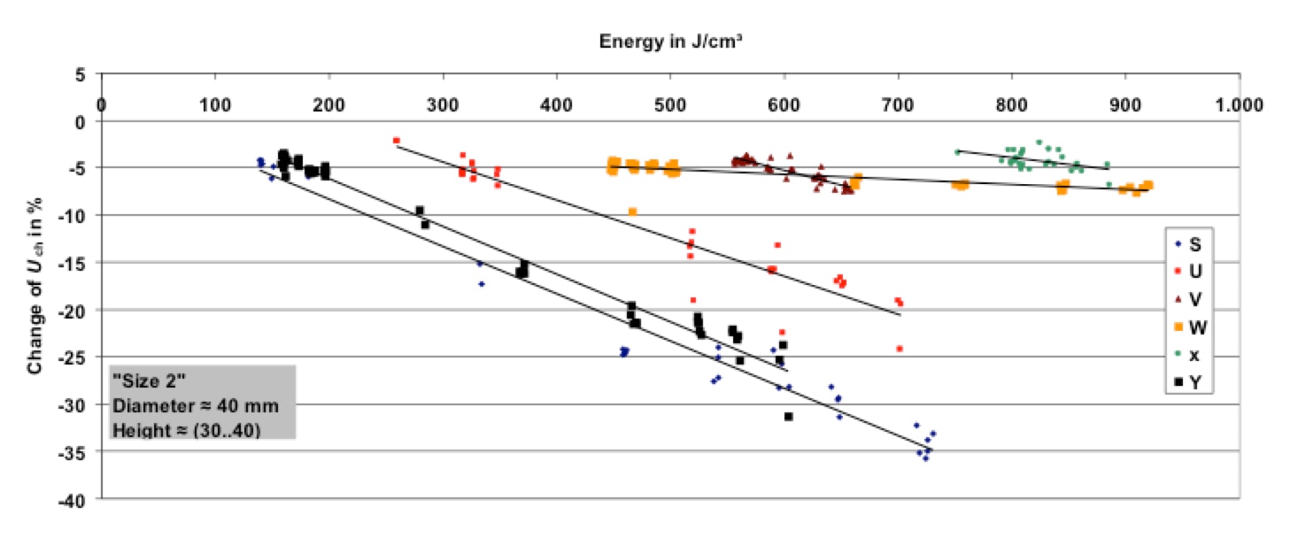
The above was the justification and motivation for changing test philosophies in IEC arrester standards, which, after long discussion, resulted in the present standards. The basis was laid by Cigré Working Group A3.17 and later by WG A3.25, who prepared two Technical Brochures that addressed energy handling issues. Fig. 2 shows the basic finding when it comes to single energy handling capability, in this case for MO resistors typical for use in station class arresters.
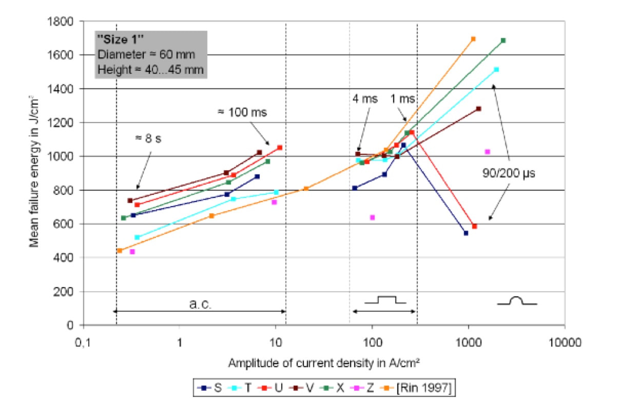

Important lessons from this investigation involving thousands of MO resistor samples supplied by different manufacturers worldwide were:
• Mean single-impulse failure energies vary approximately from 400 J/cm³ to 1200 J/cm³ for very fast impulses and even up to 1700 J/cm³. This is far above the typical design energy of 200 J/cm³.
• Energy handling capability increases with current density amplitude basically the same way as had been reported earlier. However, mean failure energy increases by up to 70% (on average by at least 20%) compared to some past investigations. This is an impressive demonstration of the development of MO resistors in terms of better material homogeneity. Still, the wide spread among the different makes, by a factor of 1.7, should motivate manufacturers to continue work toward optimizing their products.
• A key observation was that some MO resistors typically exhibit the expected increase in energy handling capability for extreme values of current density. But there also exist some makes that showed a decrease in failure energy down to values of only 500 J/cm³. The reason is a different dominant failure mechanism, i.e. dielectric failure of the coating, resulting in flashover. Until now, the ‘repetitive charge transfer rating’ test with 90/200 µs impulses has been the most challenging energy-handling test for MO resistors used in line arrester applications. While these results seem promising and lead to the question why design energy is specified so low, subsequent endurance tests have put them into perspective:
For repeated energy injection, injectable energy differs for different current densities. The higher the current density of the impulses, the lower the energy that can be injected without pre-damaging the MO resistor. The energy level that can be handled without pre-damaging the MO resistors by repeated energy injections in the case of AC stresses is close to the level of single-impulse energy handling capability and thus comparatively high. By contrast, for long duration current impulses, e.g. 2 ms virtual time duration, it is close to the typical design energy for standard arrester applications, namely in the range of 200 J/cm³.
These investigations have shown that the single-impulse energy handling capability of MO arresters is surprisingly high – many times higher than typically specified rated energy handling capability. However, if single-impulse stress at such high levels occurs repeatedly, much lower values would be acceptable so as not to damage the arrester. Overall, an arrester has a fairly good chance to ‘survive’ a few energy inputs much higher than its rated energy as long as the thermal stability limit is not affected. This might be the reason arresters have had such an excellent service record, given that excessive energy input is a rare event under standard system conditions. However, if this occurs more often, permissible injected energy definitely must be limited to the rated energy.
In the case of often-repeated, high-energy long duration current impulses, the leakage current region of the voltage-current characteristic is affected only negligibly. This means that this kind of stress has no negative effect on the arrester’s thermal stability limit. Station class arresters in substations benefit from this since very steep and short high-energy impulses are rare at these locations. But high-current impulses will affect the leakage current characteristic to differing degrees, depending on make of the MO resistor (see Fig. 3).
This is therefore an issue for distribution or for gapless line arresters. However, since such stress is generally imposed in all thermal stability tests during type testing, the arresters have proven thermal stability even under the impact of a deteriorated leakage current characteristic. That means this effect is sufficiently covered by type tests and thus not an additional risk during service.
Energy Absorbers for HVDC Circuit Breakers
HVDC technology for far distance transmission of electric power has been applied for more than 60 years and is rapidly emerging towards higher voltage levels ( 800 kV in service; 1000 kV under development). Since voltage sourced converters (VSC) in modular multilevel technology (MMC) are becoming state-of-the-art, meshed HVDC overlay grids are also becoming a realistic option. A meshed grid requires circuit breakers and many proposals have been made for their implementation. Since direct current has no natural zero crossings and as mechanical breakers do need a current zero for current interruption, the zero crossing must be enforced by external circuitry. But this does not solve the problem that, due to the flowing current, magnetic energy is stored in system inductances, which must be absorbed if extreme overvoltages are to be avoided. Every DC circuit breaker, independent of its general operating concept, therefore needs an energy absorber in parallel. This is – naturally – a MO arrester, typically arranged as an arrester bank with many MO resistor columns in parallel. Fig. 4 depicts a basic sketch of the working principle, i.e. a vacuum interrupter with a pre-charged RLC circuit connected in parallel to trigger (by the spark gap SG) and superimpose a high-frequency oscillation to the system current through the interrupter, by which artificial current zeroes are enforced.
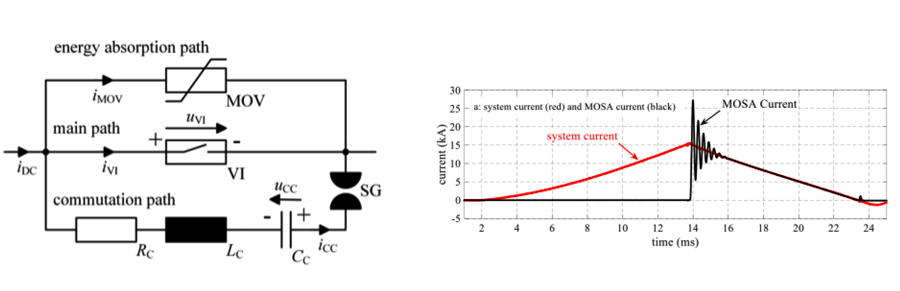
As can be seen, the current through the arrester during the DC current interruption has a characteristic shape: a steep increase to several kilo-amperes and a long lasting decay for some 10 milliseconds. Further on, the arrester might be stressed by a continuous direct voltage as long as the breaker is not disconnected by a series disconnector (not shown in Fig. 4). This is a relatively new stress scenario for MO arresters and which requires investigation of energy handling capability and electrical degradation. Unfortunately, little on this has been published so far. More than 10,000 impulses should be withstood by the arrester, for which reason the typical approach must be an endurance test with current impulse shapes as close as possible to the real application, with underlaid direct voltage stress as a worst case condition and with more than 10,000 energy injections.
All these investigations reported degradation effects in terms of reduced permissible energy per impulse for repeated impulse application, increase of the DC leakage current and increase of the clamping voltage in different degrees depending on make. For example, different commercially available makes from different manufacturers (diameter » 50 mm, height (2.5…7 mm) were investigated and showed much different ageing behavior. A notable example is shown in Fig. 5.
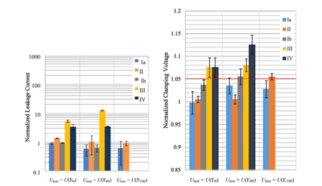
Left: Leakage current. Right: Clamping voltage.
As can be seen in Fig. 5 left, although some makes are nearly unaffected, an increase in leakage current by up to a factor of approximately 10 may occur, depending on make. This is notable but not really an issue so long as the arrester is not permanently connected to the system voltage. But clamping voltage might also be increased by more than 12% (see Fig. 5 right), which cannot be neglected and might disqualify that particular make for the intended application.
Arrester standards in general allow a 5% maximum increase of the residual voltage after any energy stress. It is further concluded from these investigations that due to the exclusively unipolar stress, DC stable material (e.g. qualified by the accelerated ageing test procedure of IEC 60099-9:2014, Clause 9.11) should be used – even if no permanent direct voltage is applied. Finally, there are clearly some makes on the market that can be used in HVDC breaker applications without restriction.
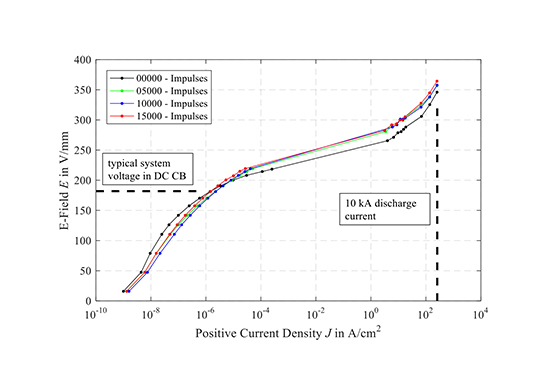
In another investigation, only one particular make was tested (diameter » 70 mm, height » 6.35 mm). Eleven samples were stressed by up to 15,000 energy injections. At the end, a failure energy test (i.e. injection of a high AC current to breakdown) was performed and compared to the known mean failure energy of new samples. Fig. 6 shows one noteworthy result on electrical degradation.
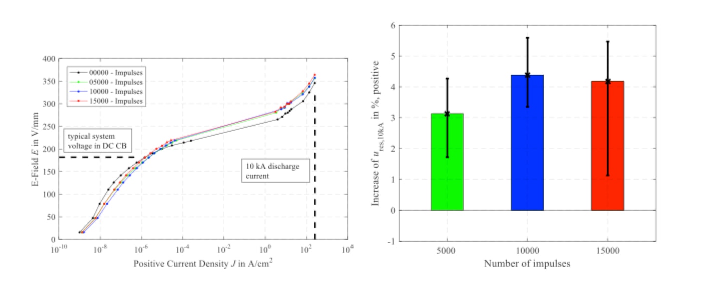
This investigation also revealed that leakage current as well as clamping voltage will be increased by this stress scenario, expressed by counter-clockwise rotation of the U-I-characteristic in Fig. 6 left. In this example, the 5% criterion of allowed maximum increase in residual voltage was met by most samples with only a few minor exceptions (see Fig. 6 right). In the final failure energy tests, the failure energy of pre-stressed samples turned out to be unchanged or even increased.
One of the lessons from this work is that application of today’s commercially available MO arresters as energy absorbers in HVDC breaker applications is certainly possible. The material should be DC stable even if the system voltage is not permanently applied. Samples that are not DC stable would typically fail during the endurance test. It has to be kept in mind that leakage current as well as clamping voltage will increase over the arrester’s full lifetime but obviously stay within acceptable limits depending on make. It should, however, be discussed in the future whether the 5% criterion in arrester standards, which presumes only moderate stress (e.g. 20 injections of rated energy) can be applied in this case, where more than 10,000 energy stresses are considered. Under these conditions, perhaps a greater change could or must be tolerated. Nevertheless, these investigations indicate that the concept of energy absorbers made up of MO resistors will work. Further research will have to be performed to better generalize these findings, which were based on only a limited number of makes and samples.

Arrester Banks
Among the benefits of gapless MO arrester technology is that many MO resistor columns can be connected in parallel and, if current sharing is carefully considered, they can evenly share energy stress. Current sharing is not an issue in the region of nominal discharge current (e.g. 10 kA), where the exponent of non-linearity is typically a < 5. A 1% lower residual voltage of any MO resistor column in a parallel-connected arrangement then means a 5% increase of current in this column. This is common practice for EHV (800 kV) and UHV (> 800 kV) systems, where several columns are typically connected in parallel. However, in the switching current region of the U-I characteristic, for instance 100…500 A, the exponent of non-linearity is higher, i.e. on the order of a = 25. Current increase due to a 1% lower residual voltage will then be 28%. This makes it challenging to manufacture huge arrester banks with sometimes 100 resistor columns in parallel and this solution may not work well in all cases.
One typical application is overvoltage protection of series capacitors where, in the event of a line fault, the full short-circuit current would flow through the capacitor. This would linearly increase the voltage drop across the capacitor unless the current was commutated to an arrester connected in parallel. Energy absorbers for emerging HVDC circuit breakers may also be of this scale.
Eventually, an individual resistor column in a bank may be overloaded and has to be taken out of service. In such cases, it is recommended to install ‘hot’ spare columns. These are exposed to exactly the same electrical stress as all neighboring columns. If these become spent, it is recommended not to mix old and new columns, which means replacement of the entire arrester bank.
Given that this is unsatisfactory from an economic point of view, investigations have been performed to determine if old (i.e. aged) and factory-new MO resistor columns can be mixed. Since in such an investigation one is looking at changes in residual voltage of << 1%, measurement of voltage given its typical uncertainty of 3% becomes meaningless. Thus, all measurements in this work were evaluated by their changes in the switching impulse current range relative to a reference column connected in parallel. The test specimens were columns of 12 MO 100 mm diameter resistors in series. Fig. 7 indicates the main result.
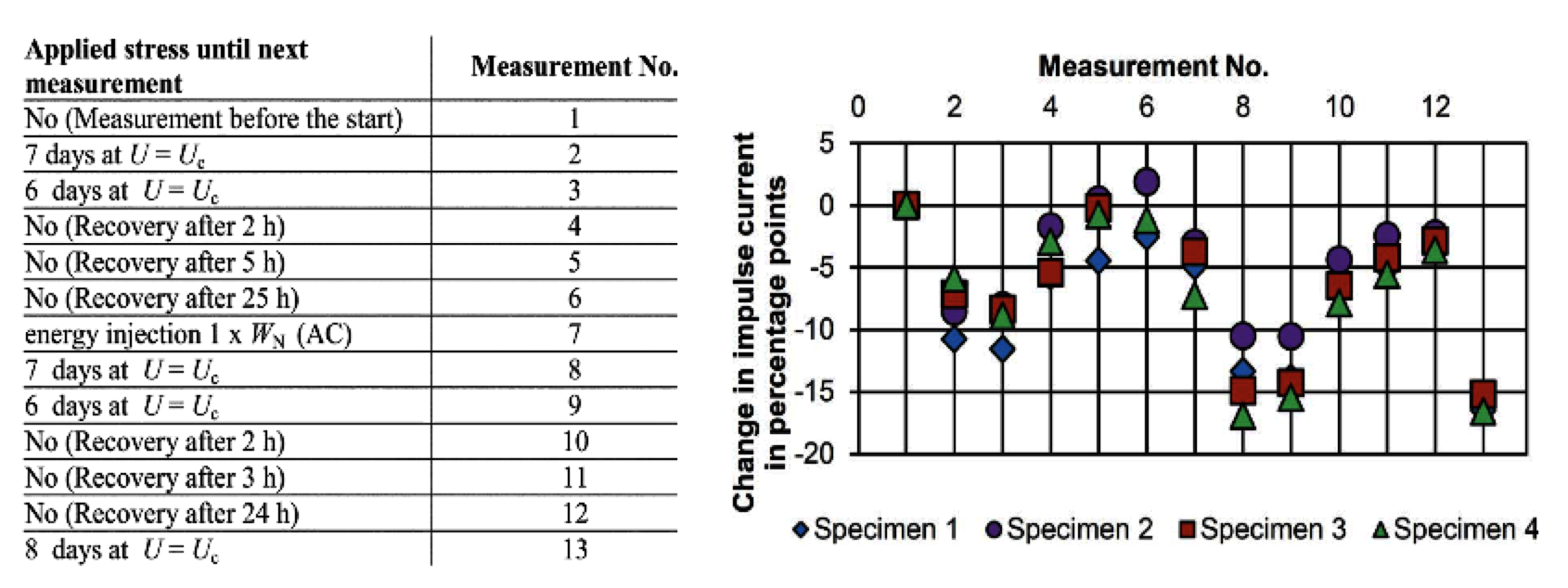
The left part of Fig. 7 shows the test cycle, which consists of 13 days with applied power-frequency voltage U = Uc, one day with no voltage applied, injection of full rated energy by high alternating current injection, 13 days with U = Uc applied, one day without voltage applied and finally 8 days with U = Uc applied. The outcome is shown at the right of Fig. 7. In summary, application of power-frequency voltage results in a (10…15) % decrease in switching impulse current compared to the reference column (corresponding to a 0.5% increase in residual voltage under the assumption a = 25). But one to two days without any voltage applied results in a near total recovery to the initial stage.
The conclusion is that individual columns, which are usually matched in the factory to the reference column, can be added to an arrester bank just two days after de-energization with no adverse impact on current sharing. This finding suggests that replacement of complete arrester banks is not necessary. Instead, individual columns can be installed any time so long as the same make of MO resistors is still available and the original reference column has been stored in the factory. Of course, this result is limited to the particular make of MO resistors investigated, although different production batches were used. Ideally, it should be verified and for other makes of MO resistors as well. Moreover, given that this research is also interesting for energy absorbers in HVDC circuit breakers, similar investigations should be performed under typical DC stress conditions.

Acknowledgment
Prof. Hinrichsen expresses thanks to Max Reinhard, Maximilian Tuczek, Thomas Heinz, Moritz Gießel, Maike Bröker, Yvonne Späck-Leigsnering, and Peter Hock, who made it possible to learn the lessons, as reported here, by their Ph.D. projects, carried out at Technische Universität Darmstadt.
1 References
[1] CIGRE TB 696, MO surge arresters – Metal oxide resistors and surge arresters for emerging system conditions, CIGRE, 2017.
[2] IEEE C62.11-1987, IEEE Standard for Metal-Oxide Surge Arresters for AC Power Circuits, IEEE Standard, 1987.
[3] IEC 99-4, First Edition, 1991-11, Surge arresters – Part 4: Metal-oxide surge arresters without gaps for a.c. systems, IEC Standard, 1991.
[4] IEC 60099-4:2014, Surge arresters – Part 4: Metal-oxide surge arresters without gaps for a.c. systems, IEC standard, 2014.
[5] IEC 60099-9:2014, Surge arresters – Part 9: Metal-oxide surge arresters without gaps for HVDC converter stations, IEC Standard, 2014.
[6] IEC 60099-8:2017, Surge arresters – Part 8: Metal-oxide surge arresters with external series gap (EGLA) for overhead transmission and distribution lines of a.c. systems above 1 kV, IEC Standard, 2017.
[7] IEC 60099-5:2018, Surge arresters – Part 5: Selection and application recommendations, IEC Standard, 2018.
[8] IEC 60099-6:2019, Surge arresters – Part 6: Surge arresters containing both series and parallel gapped structures – System voltage of 52 kV and less, IEC Standard, 2019.
[9] IEEE C62.11-2012, IEEE Standard for Metal-Oxide Surge Arresters for AC Power Circuits (>1 kV), IEEE Standard, 2012.
[10] IEEE C62.22-2009, IEEE Guide for the Application of Metal-Oxide Surge Arresters for Alternating-Current Systems, IEEE Standard, 2009.
[11] IEC TC37, PT60099-11, “https://www.iec.ch/dyn/www/f?p=103:14:14791354044797::::FSP_ORG_ID:22209,” [Online]. [Accessed 2nd September 2019].
[12] CIGRE TB 544, MO Surge Arresters – Stresses and Test Procedures, CIGRE, 2013.
[13] K. G. Ringler, P. Kirkby, C. C. Erven, M. V. Lat and T. A. Malkiewitz, “The energy absorption capability and time-to-failure of varistors used in station-class metal-oxide surge arresters,” IEEE Transactions on Power Delivery, vol. 12, no. 1, 1997.
[14] M. N. Tuczek and V. Hinrichsen, “Recent Experimental Findings on the Single and Multi-Impulse Energy Handling Capability of Metal–Oxide Varistors for Use in High-Voltage Surge Arresters,” IEEE Transactions on Power Delivery, vol. 29, no. 5, 2014.
[15] M. Tuczek, Experimental Investigations of the Multiple Impulse Energy Handling Capability of Metal-Oxide Varistors for Applications in Electrical Power Engineering, Ph.D. Thesis, Technische Universität Darmstadt, https://tuprints.ulb.tu-darmstadt.de/8455/, 2015.
[16] C. M. Franck, “HVDC Circuit Breakers: A Review Identifying Future Research Needs,” IEEE Transactions on Power Delivery, vol. 26, no. 2, pp. 998 – 1007, 2011.
[17] T. Heinz, Gleichstromschalten in der Mittel- und Hochspannungstechnik unter Einsatz von Vakuumschaltröhren, Ph.D. Thesis, TU Darmstadt, https://tuprints.ulb.tu-darmstadt.de/6805/, 2017.
[18] P. Hock, N. Belda, V. Hinrichsen and R. Smeets, Investigations on Metal-Oxide Surge Arresters for HVDC Circuit Breaker Applications, INMR World Congress: Tucson, Arizona, USA, 2019.
[19] T. Jinzenji and al., “Development of Zinc Oxide Ceramic Energy Absorbers,” IEEE Transactions on Power Apparatus and Systems, vol. PAS 101, no. 5, pp. 1429-1436, 1983.
[20] M. Bröker and V. Hinrichsen, “Testing Metal-Oxide Varistors for HVDC Breaker Application,” IEEE Transactions on Power Delivery, vol. 34, no. 1, pp. 346 – 352, 2019.
[21] IEC 60143-2:2012, Series capacitors for power systems – Part 2: Protective equipment for series capacitor banks, IEC Standard, 2012.
[22] M. N. Tuczek, M. Bröker, V. Hinrichsen and R. Göhler, “Effects of Continuous Operating Voltage Stress and AC Energy Injection on Current Sharing Among Parallel-Connected Metal–Oxide Resistor Columns in Arrester Banks,” IEEE Transactions on Power Delivery, vol. 30, no. 3, pp. 1331-1337, 2015.
[23] R. Göhler and al., “Special Requirements on Surge Arrester Design for UHV A.C. Systems above 800 kV System Voltage,” in Cigre Session, Report A3-104-2010, Paris, 2010.
[24] V. Hinrichsen and M. N. Tuczek, “Surge arresters for insulation coordination in UHV power systems – related problems and solutions,” e&i Elektrotechnik & Informationstechnik, vol. 129, no. 5 (DOI: 10.1007/s00502-012-0032-1), pp. 326-331, 2012.
[25] V. Hinrichsen, M. Giessel and M. N. Tuczek, “Thermal Stability of HV and UHV Arresters with Reduced Grading Systems,” in INMR World Congress on Insulators, Arresters, Bushings & Cable Accessories, Munich, 2015.
[26] M. Giessel, Elektrothermisches Verhalten von Hochspannungs-Metalloxid-Ableitern mit reduzierten Steuersystemen in Wechselspannungsnetzen, Ph.D. Thesis, Technische Universität Darmstadt, https://tuprints.ulb.tu-darmstadt.de/8337/, 2019.
[27] Y. Späck-Leigsnering, Electrothermal Modeling, Simulation and Optimization of Surge Arresters, Ph.D. Thesis, Technische Universität Darmstadt, submitted 2019, to be published in 2019, https://tuprints.ulb.tu-darmstadt.de/cgi/search/advanced.
[28] Y. Späck-Leigsnering, E. Gjonaj and H. De Gersem, “Electrothermal Optimization of Field Grading Systems of Station Class Surge Arresters,” IEEE Journal on Multiscale and Multiphysics Computational Techniques, vol. 4, pp. 29-36, 2019, DOI: 10.1109/JMMCT.2019.2896630.