Introduction
The need for high voltage testing at has increased dramatically over the last few years. Typically test objects include HVDC valves, AC and DC cables, line insulators, cable accessories, wall and transformer bushings, optical instrument transformers and station post insulators for different applications.
The request for non standardised tests are coming from user specific requirements (environment, system, etc) or the fact that the standards are not up to date and need to be revised and adapted to more stringent conditions. These types of tests put high requirements on the test equipment and the competence of the test engineers. The test equipment needs to be flexible and easy to move even though they are large and heavy and require installations.
Part of these specific requirements comes from manufacturers of high voltage equipment and part from transmission system operators (TSOs). One of the reasons is that the electrical power system is becoming more complex and that the high voltage equipment installed in the network are exposed to conditions not covered by the design and type testing. Another factor is that the requirements in the standards today are not stringent enough compared to the experience from service. This leads to an increase in for example test duration, new test methods and more stringent requirements.
This report summarises some of the different types of non standardised testing that STRI has encountered throughout the years.

Transient Tests
STRI has facilities allowing full scale dielectric testing of ±800 kV DC and AC components for transmission lines and substations. Also some equipment for 1100 kV can be tested in the laboratory. Type and development tests have been done on a great variety of products such as HVDC valves, high voltage circuit breakers, bushings, current and voltage transformers, insulators and accessories, high voltage AC and DC cables. Some of these products are exposed to different types of high voltage transients. We have performed a number of tests where different types of transient over voltages have been created and applied on the equipment. These tests have been both for research and development and as a requirement from the equipment manufacturer or the TSO.
One test that we have performed was to create a voltage wave with a rise time of less than 20 µs and duration of at least 1.05 s and amplitude of 1010 kV which should be applied to the test object. Another test was to have a DC voltage of 450 kV of opposite polarity on one side and apply the DC transient voltage on the other side. For this specific test two DC-generators in combination with a circuit breaker where used.
Another test performed was as follows. During 2018 we received a request to perform a test in order to create a transient with a resonance frequency, dc voltage level and time duration as closely as possible to what has been measured in field. The parameters of the test circuit were given by the client and STRI designed the test layout. In this case a 70 m long bus bar was set up outside together with a circuit breaker. The circuit breaker was open and closed in order to create the DC transient voltage.
Ice, Snow and Low Temperature Tests
There are some basic standards on how to perform tests under certain environmental conditions like e.g. ice. However, the clients usually want to represent the local conditions as far as possible and this means going outside any today existing standard.
Throughout the years STRI has performed a number of tests under ice, snow and low temperature conditions. Some of the tests are discussed below.
Development of Ice Tests
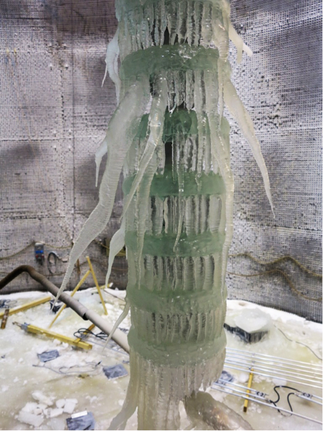
As described in [1] STRI has for a long time work closely with our customers to develop test methods for ice and snow. In order to make the testing representative and cost effective STRI has developed the Ice Progressive Stress (IPS) test method. The IPS test consists of two phases, ice deposition under service voltage and flashover performance evaluation by increase of test voltage up to flashover. Therefore the results will provide more information compared to a withstand test. The test method has successfully been applied in a number of projects and was finally included in the IEEE guide for ice test methods and procedures. An example of the ice deposited under voltage can be seen in figure 2. In this specific case a DC-voltage was applied to the insulator chain during the build up of the ice.
The general conclusion is that the test method is applicable for full scale testing and is repeatable and cost and time effective and is therefore considered as a preferable method.
Development of Snow Test
Testing under snow conditions is very difficult as it involves a large variation in test parameters. Types of snow, conductivity, temperature are examples on parameters that need to be controlled. STRI has performed snow tests on different products like insulators, disconnectors and circuit breakers.
Basically the test consists of 4 steps [2], firstly the generation of the snow with the specific properties (conductivity, size of snow particle etc), secondly applying the snow to the test object, thirdly increase the water content of the applied snow and finally the voltage application.

Low Temperature Test
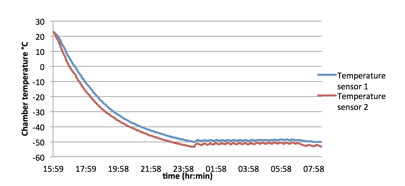
Some TSO has requirements to test the products supplied to them for extreme temperatures. With extreme in this case we mean tests performed at either -50C or -60C. STRI has a climate chamber with a bushing enabling high voltage tests such as AC, DC or impulse under cold conditions. Also partial discharges can be measured during these conditions.
For example, impulse and AC testing has been performed on medium voltage cables and cable accessories at -50C. The temperature was reduced to -50C and held there 8-12 hour depending on customer specification (see example of temperature plot in figure 3). After this the AC or impulse test was performed. In some cases a “dummy” cable with temperature sensors was placed close to the test cable to compare core temperatures in the cable conductor.
An example of a cable tested at low temperatures in the climate chamber can be seen in figure 4.
Dielectric Tests
Long Term Testing of High Voltage Equipment
We were approached by a manufacturer of high voltage equipment that wanted to investigate how their product withstands long term exposure to an AC voltage superimposed on a DC voltage. A special outdoor test circuit was designed for this purpose with a test transformer and a rectifying circuit. The product was designed for 245 kV and was tested at an elevated voltage. The test was performed for 22 months during which leakage current and partial discharges were measured.
Rapid Flashover
Testing high voltage equipment for different service conditions are can be time consuming and subsequently quite expensive, in particularly testing for different pollution levels in order to have a pollution performance curve. For this reason STRI has developed and proposed a rapid flashover method.
The rapid flashover model is based on the following principle, applying pollution on insulator followed by application of voltage. If the insulator withstands the voltage level the voltage is increased to flashover at the end of the test.
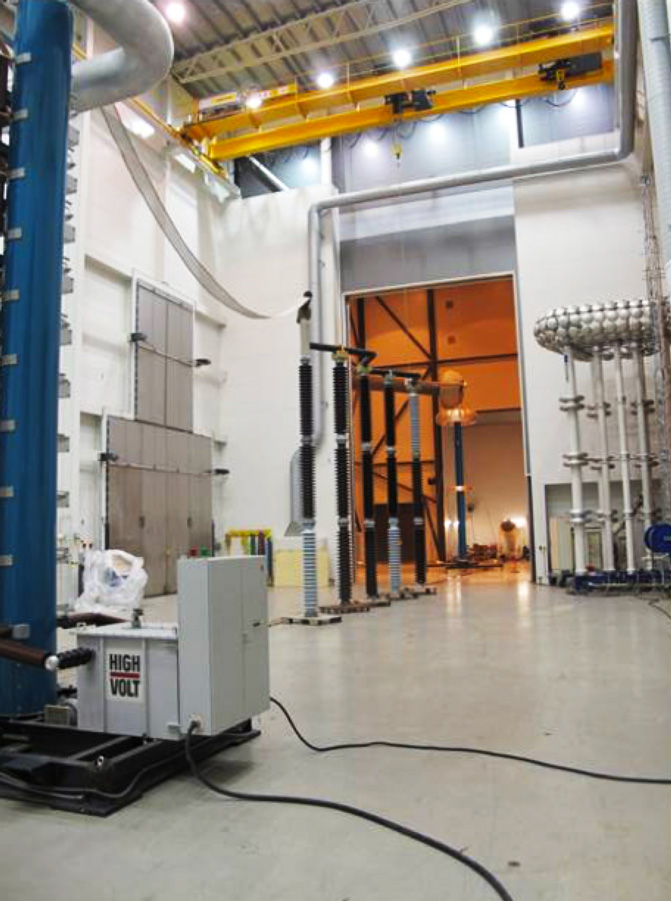
Impulse Test after One Year Prequalification Test on HVDC Cable
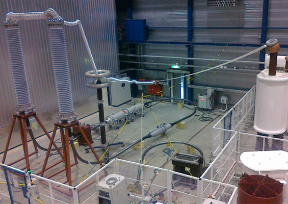
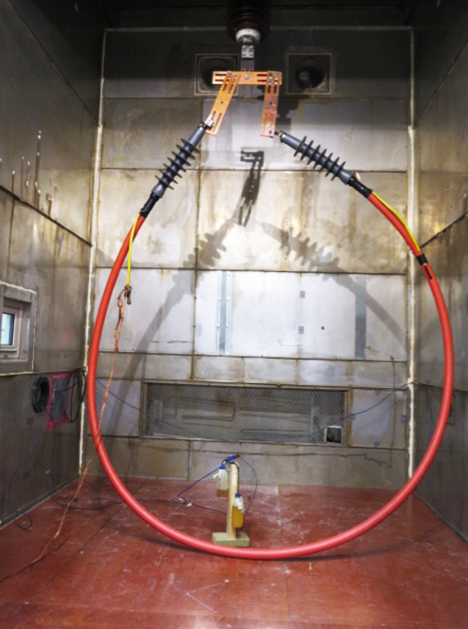
After performing the 1-year prequalification test, the guidelines from CIGRE requires that superimposed impulse testing on a 30 m section of the cable shall be done. However, the requirement of the customer was that the complete 120 m cable system with all the accessories should be tested. Applying superimposed impulses on DC-voltage with full length cable system puts extremely high requirements on the test circuit and on the individual components such as the DC-generator and the impulse generator (see figure 5). Both superimposed lightning and switching impulses were successfully performed. For lightning impulses it is not possible to fulfil the requirements in the standard as regards to front time. CIGRÉ is now updating its technical brochures regarding cable testing and the requirements on the front time will be changed to a higher value compared to what is specified in IEC60060-1.

Effects of Electric and Magnetic Fields
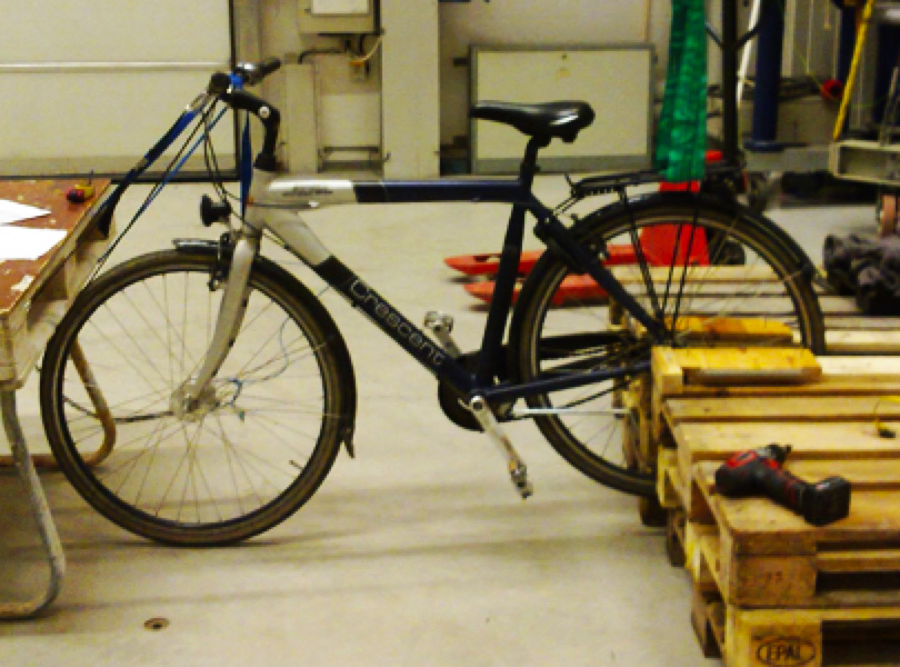
Some TSOs have experienced complaints regarding effects of electric and magnetic fields around the power lines. One issue has been people performing different activities under or around the power lines e.g. bicycling, riding horses etc.
In order to investigate if riding a bicycle under power lines can be an issue, STRI was asked to try to simulate this by measurements and an experiment [3]. First, the actual electric fields were measured under a 400 kV power line. The results showed an enhancement of the electric field with 50% when bicycling under the power line. Based on this the energy in a possible discharge was estimated to 1,1 mJ, a level without danger but would be sensible. The measurement and the estimate could not explain the phenomena that people have experienced in field. One possible explanation could be the type of cloths used. To simulate this, a test engineer cycled with different cloths in order to evaluate the difference between clothes made of synthetic and cotton material. The contribution to the discharge energy from static charging of clothes can be roughly 0,5 mJ which, in addition to the above 1,1 mJ, would give a clearly sensible increase. The influence of the clothes was that cotton gave a positive electric field and synthetic a negative electric field.
Furthermore, the possible influence of magnetic and electric fields on equipment working around energised lines has evaluated. Lifting for example insulator strings with a helicopter could potentially be an issue when working in and around energised lines. STRI simulated this by lifting a hook with a crane at the same time as exposing it to different electric and magnetic fields.
Temperature Rise Testing at Elevated Temperatures
Some customers require that the bushing is tested in a test hall with 50C ambient temperature. This is a requirement for some customers in China. One of STRIs test halls for temperature rise test has the capability to perform tests at these elevated temperatures. Recently ABBs wall bushing rated for 1100 kV DC was tested at STRI with +50C surrounding temperature and with a current of 5839 A DC.
Also a wall bushing has been tested with +45C on the outdoor side and +60C on the indoor side. Testing under these conditions puts high requirements on the test equipment (in this case installed in +45C) and also the test engineers that have to work under these conditions.

Summary
This report summarises some of the different types of non standardised testing that STRI has encountered throughout the years. The request for non standardised tests are coming from user specific requirements (environment, system, etc) or the fact that the standards are not up to date and need to be revised and adapted to more stringent conditions. These types of tests put high requirements on the test equipment and the competence of the test engineers. The test equipment needs to be flexible and easy to move even though they are large and heavy and require installations.
References
• Berlijn, S, Halsan, K, Gutman, I, Summarising knowledge from laboratory ice and snow tests on glass and composite insulators for overhead lines, Proceedings of the 15th international workshop on atmospheric icing of structures (IWAIS XV), St. Johns, NL, Canada, September 8-11, 2013
• https://sverigesradio.se/diverse/appdata/isidor/files/159/9c96b755-644d-486f-8bca-3a74613b8e68.pdf