All stakeholders in the electrical energy branch are focused on one goal: reliability. But the grid is composed of many different components, from generators to transformers, from busbars to overhead line rod insulators, sometimes with sub-components that all require specific know-how. Although this expertise can be found by related manufacturers, it is not always available when the installation is done by a third-party.
This edited past contribution to INMR by Boris Nisslé of MGC Moser Glaser in Switzerland focused on transformer bushings, which are one of the most critical sub-components when it comes to reliability of transformers. Addressed to those who handle and assemble bushings on transformers or reactors, it explains best practices to ensure the safest installation of dry-type bushings – from receiving at site until testing on transformer. It also reviews correct measurement methods as well as interpretation of the results.
Bushing Preparation
Before Unpacking
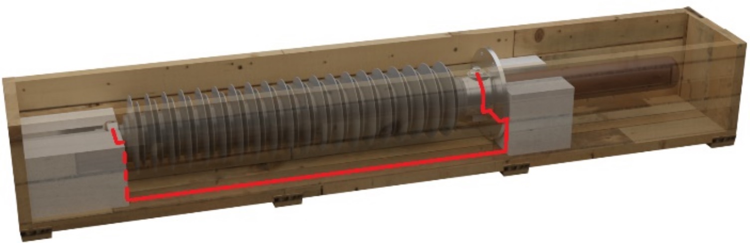
Firstly, a visual inspection of the crates must be performed to exclude major damage due to handling and/or transportation.
Then, the crate can be opened (removal of the cover) and the following must be checked
• Check nameplate of bushing, especially serial number
• Check for condensation inside plastic foil packaging
• Check for documentation inside the crate
• Additional parts (draw lead connector, external shield, additional gaskets)
General Precautions for Handling
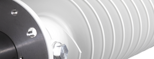
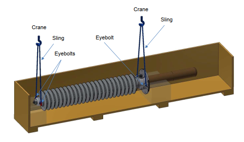
Use the pre-mounted eyebolt on flange to lift the bushing. Depending on position of center of gravity, apply lifting belt on the air side terminal or on the RIP on oil side.
Silicone material is soft and gets damaged in case of mechanical stress: do not fasten any sling and do not lay the bushing on the silicone insulator. Special attention must be taken to the coated electrodes, since even the smallest scratch may cause flashover in oil when energized.

Set-up for Testing
Before testing, the bushing must be lifted out from the wooden crate, to avoid creepage current along the crate surface (that can be polluted by humidity or dust).
If any, the protection tank must be removed to avoid additional stray capacitance and possible flashover between the bottom end and the tank.
For the test, the bushing can lay on adequate supports (non-metallic or insulated) below air terminal and flange / RIP surface or hang on crane. In this last case, specific attention must be taken to use clean slings, to avoid leakage current to ground via the crane.
Test tap should be opened and checked for humidity and/or dust. The test tap surface must be cleaned before testing if necessary.
Plastic foil must be removed from bushing surface, if any. Insulator surface must be clean and dry. Soap water can be used, but then properly rinsed with clear water and dried before any measurement. Specific cleaning products can be used as well.
Climatic parameters must be reported with the results since these influence the results: temperature of bushing, ambient relative humidity and optionally air pressure. Thus, take care that the bushing is not colder as the ambient air to avoid water condensation on the surface. Let the bushing acclimate over 12h if the bushing temperature is different from ambient temperature before testing.

Testing Before Installation on Transformer
After all above-mentioned precautions are taken, a check of capacitance and loss factor (tan ) is recommended.
Description of Bushing Parameters
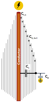
Graded bushings are composed of an insulation body (the most common are OIP, RIP, RIS), in which grading layers are inserted. These layers permit to fine grade the electrical field in both axial and radial directions. Thus, a more compact design is possible, compared to ungraded bushings. Due to higher manufacturing costs, the graded bushings are mainly used in medium and high voltage classes, whereas ungraded bushings are sufficient for low voltage applications. The focus here is on capacitive graded bushings.
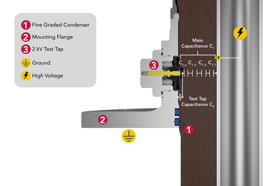
These grading layers constitute a capacitor with the previous and the next grading foil, so that the insulation part is composed of many serial- connected capacitors, resulting in a global capacitance between high voltage conductor and measurement tap, called C1.
Any change in C1 value can alert regarding a puncture, meaning a short-circuit between two consecutive layers. As a result, the remaining insulating part, considering exclusion of this shortened layer, is then submitted to a higher electrical stress than expected, reducing the expected lifetime of the product. That’s why the detection of such punctures is important, as early as possible, to avoid insulation breakdown and emergency shutdowns.
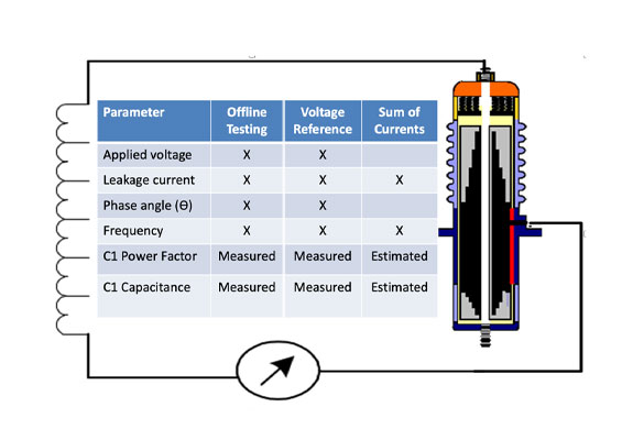
All capacitive graded transformer bushings must be delivered with a measuring tap (2 kV test tap as per IEC or NFC, 20 kV potential tap as per IEEE C57.19.00 or CAN/CSA…), which makes possible measurements of active part parameters by limiting the influence of external stray capacitances, even in assembled position.
The secondary capacitance C2 may then have two different definitions:
• If a 2kV test tap is provided, C2 is between the tap and the metallic grounded flange. This one is composed of a layer of insulation, but also of other medium like glue or air, depending on how flange is assembled. Good dielectric property is not required here, as this area is shortened in normal operation and then not submitted to any electrical stress. The measurement of C2 value is then purely informative, whereas IEC standard provides limit values for capacitance and loss factor (IEEE does not require any limitation at all).
• If a 20kV potential tap is provided, C2 is defined between the measurement tap and the earth layer. It is then exclusively composed of main insulation material and is submitted to the same dielectric requirements than C1. In this case, the capacitance between earth layer and flange is called C3, but no requirement apply to this one.
The loss factor, also called dissipation factor (DF) or tan d and assimilated to power factor, is the ratio between capacitive current and resistive current flowing through the active part. This factor should be as low as possible but depends on dielectric properties of insulation material (for example, standard limit for RIP and RIS is 0.007 (IEC) or 0.0085 (IEEE)). An increase of loss factor means reduction of insulation resistance, which can be caused by
• Presence of humidity inside active part
• Poor contacts
• Leakage current along bushing surface (polluted creepage distance)

Testing & Result Expectations
Main Capacitance C1
To measure the main capacitance and the loss factor tan d, the HV cable must be connected to the central conductor, usually at the air side terminal. The measurement input should be connected to the measurement tap and UST-method (Ungrounded Specimen Test) must be used. The flange must be grounded.
To obtain the most accurate results, it is not recommended to let the measurement tap cap closed and measure from the flange, even if it would be theoretically correct.
Test voltage must be in range 5…10 kV at 50 Hz or 60 Hz, to be comparable with nameplate value. Other frequency can be applied for future reference value, but results cannot be compared to the manufacturer data.
Due to different environment, the stray capacitance at site is different than the manufacturer one. As well, the temperature influences the capacitance value (approx. 0.1%/K). Thus, a deviation of capacitance towards nameplate will be observed (up to 10% may be normal): the key point is, that this observed deviation must be the same by all similar bushings tested in comparable conditions. If not, a failure can be suspected, either in the bushing or in the test set-up. Manufacturer should then be contacted for further investigation.
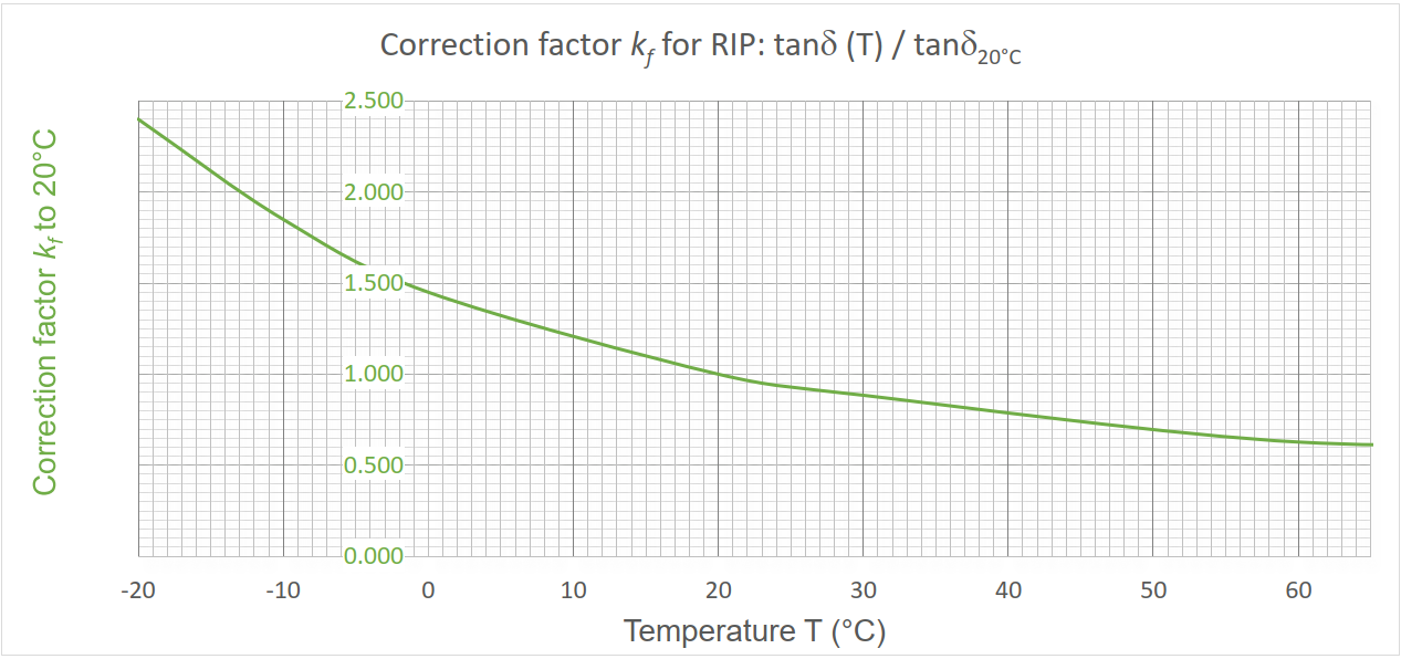
In the same way, loss factor value is influenced by the surroundings, mainly the temperature, humidity, and surface pollution. A correction curve is provided by each bushing manufacturer to be able to compare measured value with nameplate (see Fig. 4). Correction curves are different for each product type (OIP, RIP, RIS…) and each manufacturer, so ‘typical’ curves implemented in some measurement devices should not be used without precaution.
Note: Loss factor decreases with increasing temperature in range -20…+60°C. It must be ensured that the correction factor is applied correctly.
After application of correction factor, the measured loss factors of all bushings should be similar and should not have significantly increased compared to nameplate.
Secondary Capacitance C2
To measure the secondary capacitor C2 (capacitance and loss factor tan d), the HV cable must be connected to the measurement tap. The measurement input should be connected to the grounded flange and thus GST-method (Grounded Specimen Test) must be used. The main conductor should be grounded.
In case of a 20 kV potential tap, the capacitor is composed of main insulation material, so the previous section applies.
For other cases, the capacitor C2 is not composed of several serial connected capacitors, so that puncture cannot happen. Thus, if the 2 kV voltage withstand test passes successfully, the C2 should be considered as insulated, then healthy.
Due to different materials composing the C2 insulation (resin, glue, oil, air…), both the capacitance and the loss factor can be very dependent on temperature and/or humidity during measurement. For the same reason, it is almost impossible to provide a correction curve for C2, as it depends on the thickness ratio between different components (incl. manufacturing tolerances). As the deviation caused by testing environment can reach up to 200%, it is impossible to make a diagnostic with only a measurement. To be helpful, this measurement must be performed on several bushings in similar conditions to compare results. The higher the number of samples, the more reliable the analysis is.
Thus, the results of C2 measurements don’t permit – and must not be used – to conclude regarding diagnostic of the bushing main insulation. In case of an abnormal deviation, a further investigation is required.
For C2 parameters, there is only one acceptance criteria: the observed deviations of capacitance and tan d should be similar for all tested bushings (with same ratings).

Installation on Transformer
After above-mentioned measurements have been performed, the bushings ae ready to be installed on transformer. Following steps must be observed:
• Bushing oil part must be visually inspected and cleaned (use Ethanol or acetone, no water!)
• Sealing surfaces must be checked and cleaned if required;
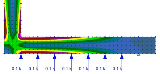
• Check presence of sealing between transformer and bushing flange. In case of a flat gasket, its design should be in accordance with sealing manufacturer recommendations: if the sealing surface is oversized, it may result in a significant mechanical overload in the flange plate and damage it: use of a thinner gasket with the same surface pressure reduces up to 88% the mechanical constraint in the flange plate;
• High-current connection between transformer winding ang bushing (soldering, crimping or screwing) must be done properly to avoid hot-spots due to high contact resistance
• Bushing flange must be screwed in cross to ensure the best sealing compression;
• The bushing head must be finalized as per manufacturer installation manual and tightness must be ensured – otherwise oil will leak and insulator will be damaged;
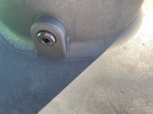
• Bushing’s flanges are usually delivered with an earthing hole / screw: this earthing point must be solidly connected to ground by an external cable. The assembling screws are not considered as proper earthing;
• All purging screws (in flange for evacuation of air trapped in transformer turret and in head for evacuation of air trapped in inner tube in draw lead applications) must be open during oil filling process and tightened at the end;
• In order to avoid flashover in oil, a waiting time must be observed after filling the transformer before applying any voltage, to ensure all trapped gas could escape;
• Offshore installation: special care must be taken to avoid corrosion of parts and/or of connection points. Bushing manufacturer recommendations must be followed to ensure long-term reliability;

Testing on Transformer: Fingerprint
As mentioned above, the parameters of the bushing differ according to environment. This is especially true once the bushing is installed on the transformer, as several additional factors will influence them, mainly the capacitance:
• Type and design of corona shields
• Diameter of transformer turret, especially where the CT-pocket is long
• Presence or not of a current transformer over the bushing bottom part
• Distance between phases
Because of these factors, it will be difficult to make a reliable diagnostic by measuring the bushing in the future. That’s why we recommend performing at least a capacitance and loss factor measurement on the bushing after their installation on the transformer: this measurement is then much more precise than the nameplate values and should be considered as reference for future measurements (fingerprint).
The recommended test procedure should be taken from the above.
After testing, the test tap cap must absolutely be reassembled to ensure proper grounding of the earth layer:
• O-Ring must be clean and properly installed in the cap
• Tighten the cap with recommended torque (see manufacturer assembling manual)
Maintenance
Under normal operating conditions, dry-type bushings are free of maintenance.
Anyway, under high polluted environments, the insulators should be cleaned to ensure the best hydrophobic properties. Time interval between interventions depends of course on pollution severity level and must then be defined by the operator for each site.
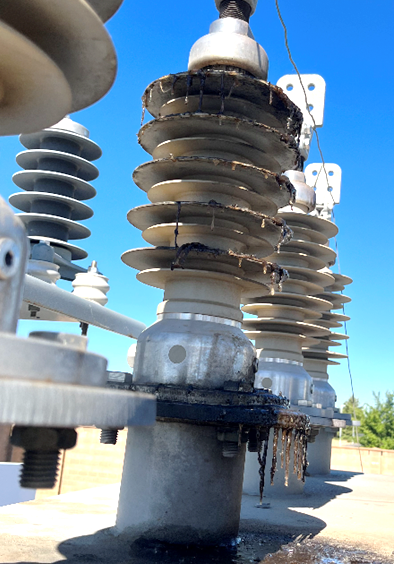
An on-line visual inspection can be performed at regular time intervals to detect major issues (oil leakage, insulator damage…).
A thermographic analysis (thermal camera) can be performed, during operation as well, to compare temperature between bushings of all phases, especially contact temperature to detect any degradation of the contact.
An off-line measurement of capacitance and loss factor is recommended every 5 to 8 years.
In addition to ambient parameters (temperature, pressure, relative humidity), the oil temperature must be recorded too during each measurement, as the bushing active part is usually warmer than ambient temperature. Depending on bushing’s length inside and outside of transformer, an average temperature should be considered to determine the appropriate tan d correction factor.
After application of correction factor, the loss factor should not have significantly increased compared to previous measurements in similar conditions.
Conclusions
A bushing looks like an easy component in comparison to a transformer, but its function is very important and its reliability vital for electrical power systems. In addition, delivery times for new bushings are very important (from 20 weeks to more than one year), that is why it is necessary to take the highest care during manufacturing, handling, installation, and testing of bushings to avoid emergency situations.
Simple tips are provided to avoid physical damage, bad measurement results, misinterpretation of results as well as to significantly reduce risk of failure during operation. Following the above-mentioned steps will permit to spare a lot of precious time to everybody by avoiding non-grounded claims to OEM or even avoid cost intensive emergency site repairs. Safe work by trained people ensures the best reliability for the system and the best image for all involved in the project.
References
[1] IEC 60137 Ed. 7, Insulated bushings for alternating voltages above 1000 V, 2017.
[2] IEEE C57.19.01, Performance characteristics and dimensions for power transformer and reactor bushings, 2017.
[3] ABB, Bushing diagnostics and conditioning, 2750 515-142, Rev. 5, 2021.
[4] HSP, Installation, operating and maintenance instructions, Range SETFt, 2021.
[5] Moser-Glaser, TD2019-11-Rev.C, Installation instructions for transformer bushings oil-air, 2021.