In many countries across the globe, lightning is a leading cause of transmission and distribution line outages. In Mexico, for example, the Comisíon Federal de Electricidad has estimated that more than 50% of line failures have traditionally been linked to lightning. To reduce these outages, starting about 2000 CFE began a program of widespread application of line arresters and selected the externally gapped (EGLA) type due to perceived advantages such as failures not adding to the system, pollution level not being a problem and no risk of disconnector device failure. Another important consideration was that EGLAs available in the local market were regarded as offering an excellent cost-benefit ratio along with lower installation requirements. Over the period from 2007 to 2017, CFE’s 230 kV & 400 kV network grew from about 47,000 km to over 60,000 km while outage rate during this period decreased from 1.17 to 0.57 at 400 kV and from 1.27 to 0.59 at the lower transmission voltage.
In the case of the 13 kV, 23 kV and 138 kV systems, which together grew during this period from about 369,000 km to more than 831,000 km, both gapless and EGLA type arresters are being utilized. However, the proportion of EGLA types has increased steadily due to difficulties in identifying gapless arrester failure from varistor block degradation or moisture ingress. Either could mean possible permanent failure on systems. By the end of 2017, more than 400,000 EGLAs had already been installed on CFE’s T&D system from 13 kV to 400 kV, of which more than 85,000 were in service at 115 kV and almost 10,000 at 230 kV and 400 kV.
As explained in this edited past article, contributed by experts in the T&D Dept. at INEEL, experience has shown this to be a good economic as well as technical solution.

Unlike for gapless arresters, establishing proper selection criteria is comparatively less critical in the case of EGLAs. Energy capability and rated voltage data are indicated by the manufacturer and it is also not necessary for the user to specify pollution level, creepage distance, MCOV, TOV, etc. Another advantage is that the varistor blocks in EGLAs are not exposed to possible degradation caused by thermal instability while failure due to pollution and improper operation of the disconnector device are also not factors. In this regard, an additional point of possible system failure is eliminated.
In the case of Mexico, for example, there have been no reported instances of EGLA failures due to varistor degradation, moisture ingress or pollution. At the same time, outages due to arrester failures have decreased significantly. Permanent outages due to arrester failure have also been decreasing as another potential point of system failure is eliminated. EGLAs applied on distribution systems in Mexico have helped avoid outages as well as damage to equipment due to induced lightning overvoltage.

CFE Experience
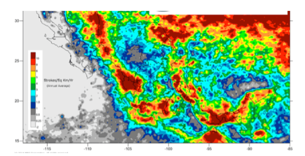
CFE has installed more than 80,000 EGLAs on 115 kV lines across the country with excellent results. However, over the years up to 2017, the arrester class used has been updated from Class 1 to Class 2 (i.e. with greater energy capability) because lightning currents have increased to more than 100 kA in some areas (see Fig. 1). For example, overhead distribution and transmission lines in central, southeast and northwest of Mexico are exposed to high levels of atmospheric lightning. Because of this, distribution and transmission systems in these areas have had an average failure rate of up to 20 outages/100km/year.
Induced overvoltages from lightning currents are the most frequent cause of failure on CFE distribution systems, with relatively less frequency in the case of 69 kV and 85 kV sub-transmission lines. These are generated by lightning strokes near the line. Indirect lightning induces rapid electrostatic and electromagnetic transient voltages to the system. Depending on stroke distance and lightning current, voltage magnitude from induced lightning currents can be considerable and the affected induced area could be up to 250 m around the line. According to statistical data, each direct lightning stroke results in 5 registered induced overvoltages. Since 80% of lightning outages are due to induced voltage and 20% to direct lightning, it has been important to consider this factor for distribution systems.
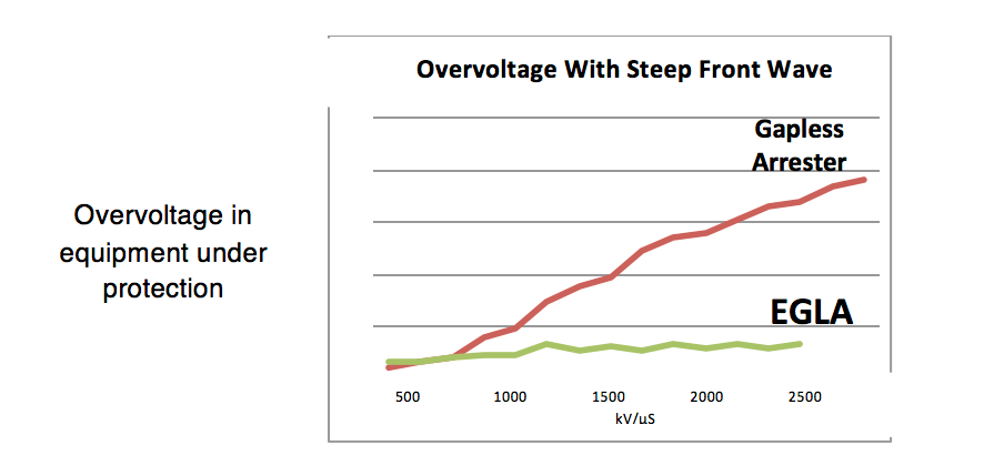
It has also been important to take into account the numbers of surge arresters to be installed along the line or in areas with high incidence of lightning. The span rate between arresters must also be considered in order to reduce failures by induced overvoltages, as outlined in IEEE Guide 1410. In the test laboratory, it has been found that induced voltage has a waveform with a steep front on the order of nano-seconds. A gapless arrester cannot deal with this whereas EGLAs can because, in their case, operating voltage depends on the gap and not on waveform (see Fig. 2). To confirm this, applied steep front wave overvoltages were applied in the laboratory to a gapless arrester as well as to an EGLA (from 500 to 3200 kV/µs). Satisfactory results were obtained for the EGLA whereas the gapless arrester allowed the overvoltage to reach the equipment being protected.
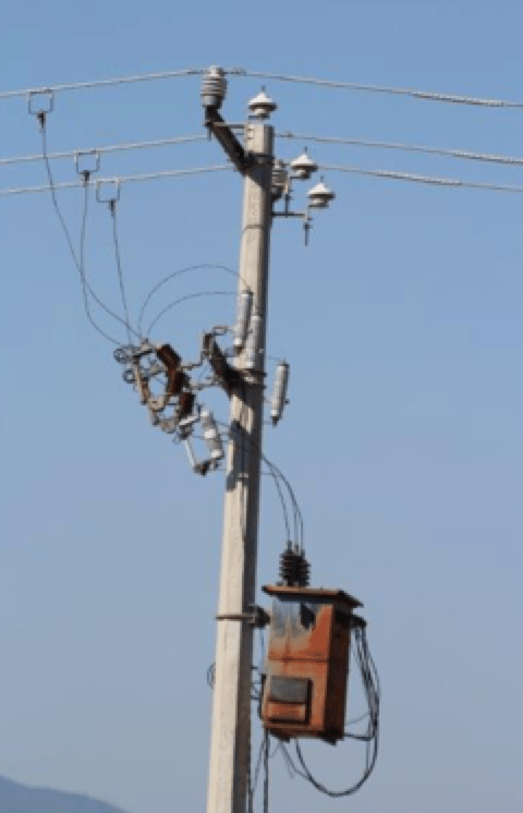
Based on the above, CFE has been using EGLAs against lightning induced overvoltage on its 13 kV, 23 kV and 34.5 kV lines with good results as system outages decreased by more than 80 % (see Figs. 3 & 4). Percentage of transformer failures caused by lightning has decreased as well with the CFE installing distribution EGLAs according to the guidelines shown below:

If an insulator fails by lightning, it will use the same path and earth reference that detected the lightning and the EGLA will be installed without adding an earth system or electrode;
• Install EGLA set (i.e. 3 phases) each 250 m for regions with ≤ 5 strokes/km2/year and each 150 m for more or with lightning current ≥ 50 kA;
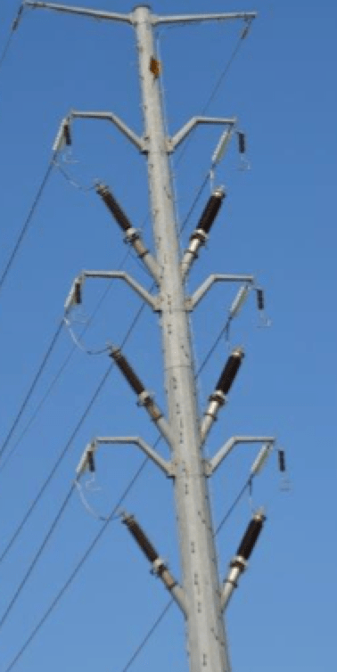
• Install EGLA set (i.e. 3 phases) before and after the pole where a transformer is installed, while keeping the existing gapless arrester. In some cases, the EGLA set is installed on the same pole with the transformer (Fig. 3).
• Install EGLA set (3 phases) each 350 m in feeders that have been over-insulated, i.e. using a higher BIL insulator.
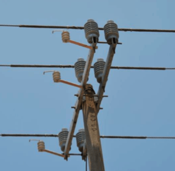
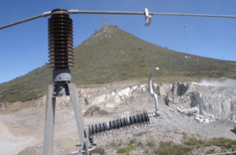
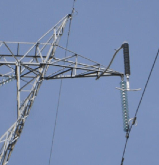
On transmission lines, adding another potential point of failure due to any new equipment is critical and therefore CFE decided to select EGLAs to avoid this risk. Application of EGLAs is done based on the following criteria: Class 2 and 3 (according IEC) are installed for regions with a high incidence of lightning, i.e. ≥ 5 strokes/km2/year and/or with lightning current >100 kA, even for 69 kV and 115 kV sub-transmission lines. In order to determine the frequency and magnitude of lightning, CFE has been using a lightning current counter on 115 kV lines in southern Mexico (see Fig. 5) with EGLAs (Class 3) being installed. For example, in one year this current counter registered 185 events, with 86 of these being more than 100 kA. In fact, on this particular transmission line, an EGLA Class 1 had failed and, because of this experience, a Class 3 EGLA was installed on the upper phase and Class 2 EGLAs on the lower phases of the TAS tower type (see Fig. 8).
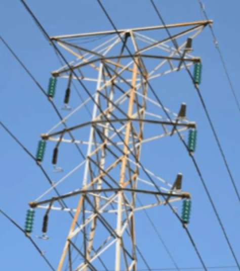
In the case of transmission lines, the EGLAs have been installed under the following general guidelines (see Figs. 6 to 12):
• If the insulator string failed by lightning, CFE will use the same path and earth reference that detected the lightning and install the EGLA without adding an earth system or electrode;


• Install EGLA set (3 phases) on tower of any type with a history of past failures due to lightning. Install EGLA set on the towers both before and after this tower;
• Install EGLA set (3 phases) on any type of tower at high altitude where correction of the insulation string level was needed and the cost is higher than that for installation of the EGLA;
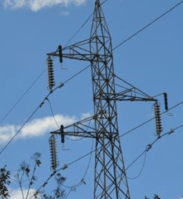
• Install EGLA set (3 phases) on TAS tower types (with one conductor for guard line at the center of the tower) and with span of more than 300 m for 69 to 138 kV lines (see Fig. 8);
• Install Class 2 or 3 EGLAs (according IEC) in regions with lightning current >100 kA;
• Install Class 2 or 3 EGLAs at cable transition points since this helps avoid terminal or cable failure caused by induced overvoltage (see Fig. 9).

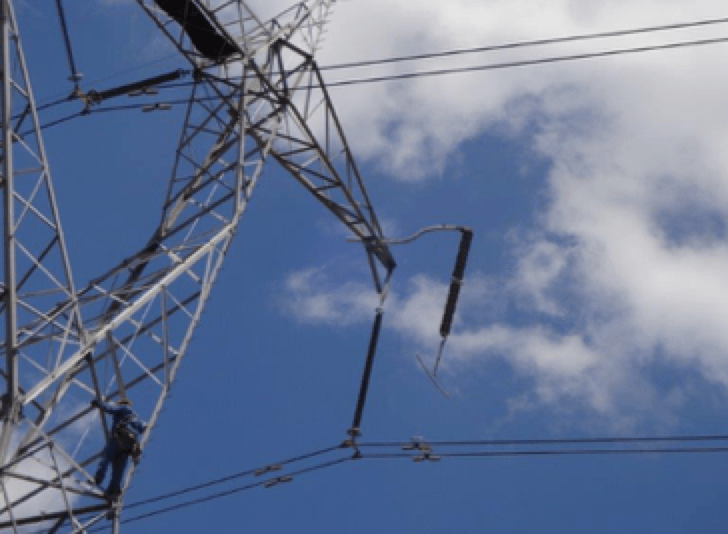
CFE installs EGLAs with the line energized in the case of 13 kV to 230 kV. So far, there have been no reports of failure during the installation procedure and continuity of service to customers has not been adversely affected.
Conclusions
Use of gap type arresters (EGLAs) in Mexico has improved performance of transmission and distribution lines exposed to atmospheric lightning and the CFE has been replacing gapless arresters with EGLAs in many areas. As a result, the population of EGLAs installed has increased exponentially over past 10 years. Up to now, there have been no reports of failures of these gapped arresters due to varistor block degradation, ingress of moisture or external pollution. Moreover, there have also been no reports of permanent outages caused by gapless arrester failure.