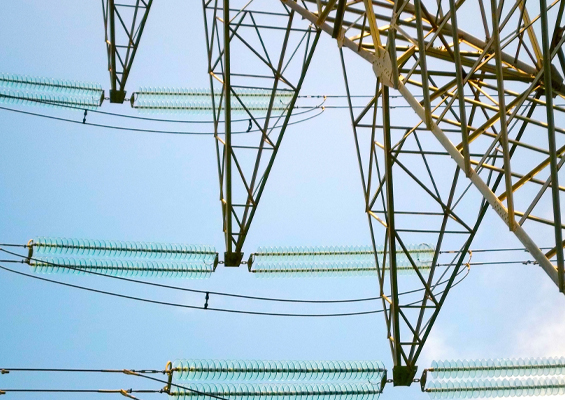
A decade ago, a utility, located in Ontario, Canada sponsored research aimed at exploring criteria for safe live line replacement of defective polymeric insulators. The specific incident that triggered the investigation arose during the upgrade of a circuit whose insulation was being changed from ceramic to polymeric. As soon as the line was re-energized, problems arose with the new insulators and caused almost immediate line trips. Faced with the need to change out the failed insulators and also to maintain reliability targets, the utility became concerned about the broader issue of worker safety whenever circumstances required composite insulators to be replaced live line. A research project was therefore launched to investigate why the failures took place and to determine if there could be a low-cost methodology to ensure worker safety whenever changing out composite insulators using live line techniques.

The problems that arose at the time the upgraded circuit was energized were traced to a batch of silicone rubber insulators judged to be defective. Fortunately, quality control procedures by the utility allowed identifying exactly where these insulators had been stored and installed on the line. This offered the possibility of selectively replacing the damaged units without having to take the upgraded line out of service again for another large-scale change of insulation. However, to plan such a replacement program it was first necessary to establish criteria for safe live line work procedures under these circumstances.

It was not immediately clear whether the failed insulators were already defective when they were delivered by the manufacturer or whether the defects arose as a result of mishandling. Inquiries quickly determined that these insulators had been continuously exposed to large amounts of water during storage and that the cardboard boxes in which they had been stored had completely degraded. Similarly, the plastic bags in which each insulator was packaged were visibly wet inside and water was beading on the surfaces of affected insulators. Most utility personnel would acknowledge that these were not the proper conditions to store or use any live-line tool. In fact, these adverse storage conditions first led researchers to contemplate using excess humidity as one of the stress factors to induce similar types of failures in a laboratory.
A sample of 40 equivalent silicone insulators with a dry arc distance of over 1 m were selected for the investigation. Creepage distance was not judged relevant here since contamination performance was not the issue. Rather, the goal was to fail the insulators only partially instead of fully to determine how bad they could become while still being able to be successfully changed out using live line techniques. In this regard, the insulators were overstressed using a combination of humidity and overvoltage to the point of initiating partial tracking along the microscopic interface between the rubber weathersheds and the internal core rod. This phenomenon is known as ‘flashunder’ to distinguish it from flashover which takes place externally and also from internal arcing which generally occurs within the material itself.
The time required for moisture to diffuse into the silicone housing and to reach equilibrium with the humid environment was on the order of about one week. This was relatively quick and much faster than would probalby have been the case for equivalent insulators made of polymer materials such as EPDM. This is explained by the comparatively high rate at which water can migrate through silicone rubber material.
The typical physical manifestation on many of the insulators that had failed by flashunder were tiny pin holes in the silicone sheath. These were so small that they could not easily be seen by the naked eye, even from a distance of only about a meter. This meant that simple visual inspection of such insulators would probably not be sufficient to detect insulators that had failed or were in the process of failing due to flashunder. Existence of these tiny holes might not in itself pose a problem for an insulator in all cases but would probably depend on environmental factors such as weather.

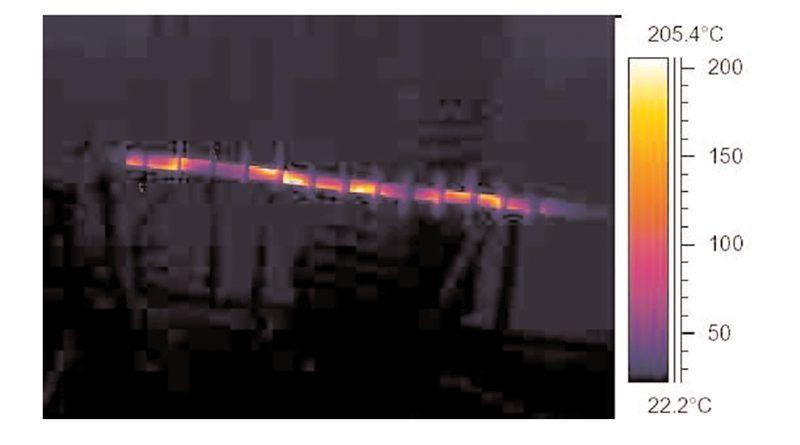
Given the relative difficulty in visually identifying insulators with such damage, an important element of the research consisted of assessing, in a laboratory, different inspection methodologies in terms of their ability to monitor the flashunder failure process. Because these types of failed insulators are difficult to detect by normal inspection procedures, it was seen as necessary to find more effective detection criteria. Ultraviolet inspection was ruled out as providing any practical help in this regard, either during day or night, simply because the trouble is taking place in an area below the surface and the silicone housing blocks the UV. Similarly, electromagnetic and stereo ultrasonic surveys would also not provide sufficiently detailed input. Rather, thermal inspection was judged the most suitable methodology in this situation.
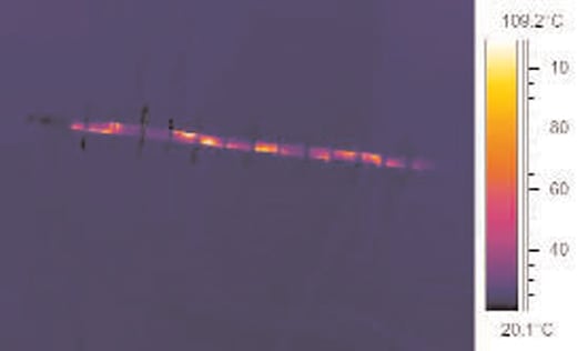
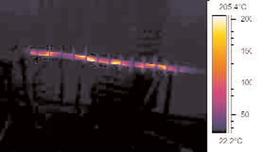
To illustrate the value of such an inspection, two thermographic images were generated on insulators that had been deliberately overstressed in the laboratory so as to induce flashunders. The first image showed the impact on heating as tracking developed during the overstress procedure. In the second image, the path was completed and temperature doubled in the affected region. This was precisely what an impending failure would look like, even if an extreme example. Basically, monitoring revealed what was happening as the insulator was failing. Of the 40 insulators involved in the overstress test, over half were somehow degraded yet still appeared normal and ran ‘cold’ during themographic testing. While all of these would fail eventually, the key question was: would it be safe to replace them live? Another thermographic image depicted how one of the 11 most damaged insulators in the test sample appeared under line voltage. In this case, the clear safety message was that if thermography reveals this type of result, an outage should be taken to replace the affected insulator.

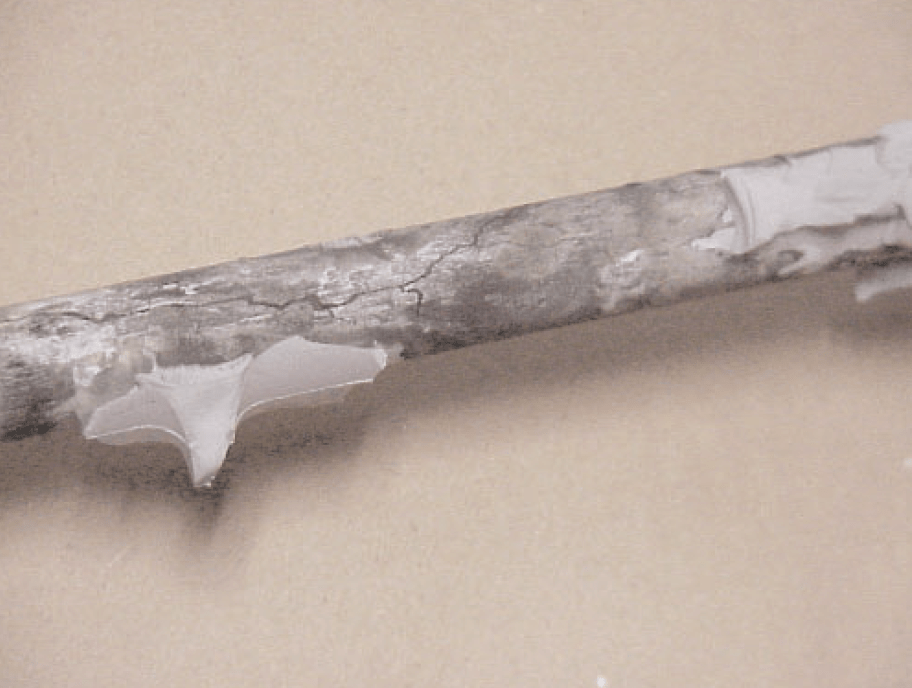
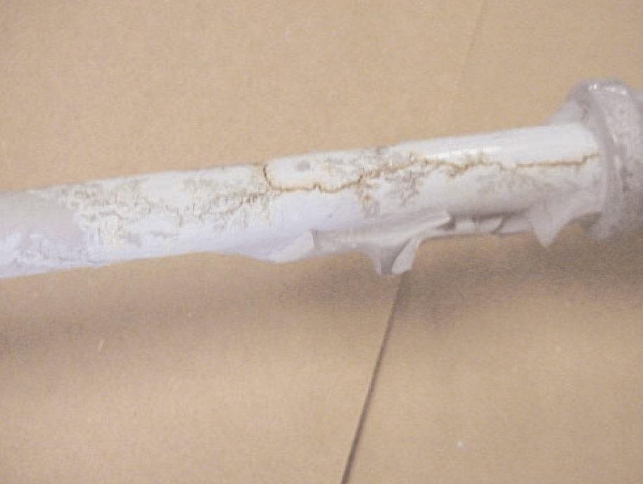
As part of the laboratory investigation, the silicone rubber housings of several of the deliberately-failed insulators were peeled away in order to examine the nature of damage in the interfacial area below. In some instances, long tracking notches were clearly visible although they did not run the entire length of the rod. These appeared to closely match the temperature rise pattern observed in the thermal images.
Another element of the research involved conducting switching surge tests on damaged test insulators under a typical set-up associated with live line practices. Flashover resulting from the surge started initially along the exterior surface of the insulator but then quickly entered into the pin hole and track area below, leading to flashunder. This then represented unsafe working conditions and a stop work order would need to be issued if replacing these insulators live since workers would be exposed to a risk they should not have to face.
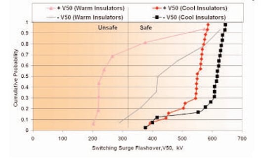

A chart was created that illustrated test results of a live line work method involving a particular configuration of the insulator, hot stick and worker. Such results would of course change from one working configuration to another and therefore utilities should aim to standardize their work methods so as to benefit most from such testing. Given the maximum switching surge possible on the system, this chart helped identify when safe working conditions deteriorate into unsafe conditions, based on cumulative probability of a flashover. Positive surges clearly have a more profound influence on failure probability than negative surges and this is in fact a well-established physical phenomenon. It was not completely clear why the extent of separation of safe and unsafe conditions for warm insulators (anything above ambient temperature) was greater than for cold insulators (ambient temperature). Possibly, diffusion of light weight silicone oil back into damaged areas might play a role in recovery.
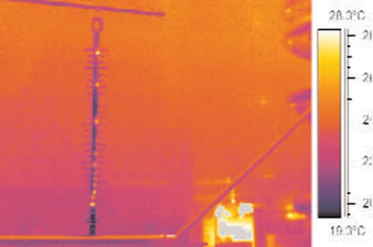
Thermographic inspection of overhead lines is usually a routine maintenance procedure at most utilities. If during such an inspection, personnel identify a composite insulator with a ‘lit up’ image, it clearly should be replaced. This however woud need to be distinguished from what is a normal small amount of activity at the line end of an insulator in service. It is the linear stripe of heat that is most characteristic of the flashunder phenomenon.
The value of this type of research lies principally in assisting utilities to make the decision on whether to replace damaged composite insulators using live line methods or whether it is preferable to take the affected line out of service. When a line crew shows up several days after the initial inspection reveals a problem, they should bring the thermographic equipment back in order to take current readings to help in making this decision.
One of the problems with relying on this inspection methodology to make the decision lies in the cost of thermographic instruments. Another issue is that an experienced operator is often needed to make a correct diagnosis of what is being seen. In this respect, an empirical Guide for relating temperature profile to extent of damage would be highly beneficial – much along the lines of the STRI classification system for hydrophobicity. Requiring insulator manufacturers to conduct electrical testing of their insulators as they leave production is not really a solution. Rather, testing must be done in the field to catch those insulators that have either been stored improperly or become damaged during handling.