The global energy transition is increasing the need for HVDC links. This means new substations with modern voltage sourced HVDC converters, that use IGBT/IGCT semi-conductor switching elements, converter reactors, etc. However, ionization of airborne particles from the electric field between poles exacerbates pollution challenges in this application since particles, drawn by the electric and magnetic fields, deposit a rapidly growing pollution layer on insulators.
At the same time, increasing HVDC voltages, power ratings and loss evaluation result in bigger and heavier equipment, increasing the mechanical strength required from support insulators. These need to handle higher compression forces, combined with increased flexural stresses coming from seismic requirements and high wind-load or short circuit forces from magnetic coupling between reactors. At the same time, they must ensure minimal flexion.
Industry is solving these challenges by combining high strength porcelain insulators coated with RTV silicone to improve pollution resistance under DC applications. In fact, RTV materials have now moved away from traditional on-site application to coating by insulator manufacturers under controlled industrial conditions. The new IEC TS 63432: “RTV silicone rubber coated insulators for AC and DC high-voltage applications – definitions, test methods and acceptance criteria” will only accelerate the trend.
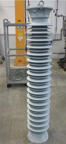
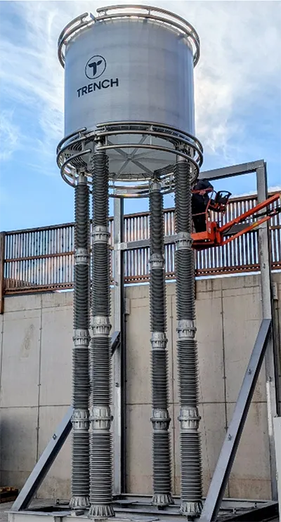
This edited contribution to INMR by Markku Ruokanen and Radoslav Strenk at the Insulator Technology Group, in co-operation with Klaus Pointner at Trench Austria, reviews design, manufacture, and homologation steps for RTV coated C8-2550 porcelain post insulators. These are being applied for a 500 kV HVDC air-core dry-type reactor support as a part of an HVDC-link using subsea cable connections between converter stations.

The ongoing energy transition has increased demand for HVDC links across the globe. At the same time, the need for energy efficiency has made HVDC transmission lines the preferred solution when it comes to overhead lines longer than about 600-800 km or about 50 to 70 km cable connections. Integration of bulk offshore wind energy without modern VSC converter technology is often not feasible.
DC links are also an excellent way to interconnect local or national grids because HVDC allows power exchange between asynchronous grids. This gives better control of power flow and helps stabilize grids and avoid cascading failures. DC links are essential as well to integrate renewable energy sources such as offshore wind parks or solar power generation from remote areas to load centers. In addition, HVDC backbone systems are planned and integrated for the same purpose.
These developments require more converter substations with adapted equipment for AC/DC conversion, converter transformers, IGBT/IGCT valves, air-core dry-type converter reactors and sometimes smoothing reactors, just as some examples. Such heavy equipment requires insulation solutions both for mechanical strength and increased creepage distance, especially when there is a challenging pollution environment. RTV-coated ceramic insulators combine high strength and low flexion with enhanced pollution performance with HTM silicone-coating.
Isostatic Ceramic Post Insulator Design & Manufacture
The isostatic manufacturing process was developed during the 1970s for the needs of powder metallurgy and allowed production of metal alloys or ceramics that could not be manufactured by any other technology. In this process, a rubber-mold is filled by dry powder, pressed with a very high-pressure (up to 1100 bar) to yield the desired shape to the product. In the case of hot isostatic pressing, temperature is raised to several hundreds of degrees of Celsius to complete the sintering in the same operation. For cold isostatic pressing, this is done by a hydraulic process at room temperature.
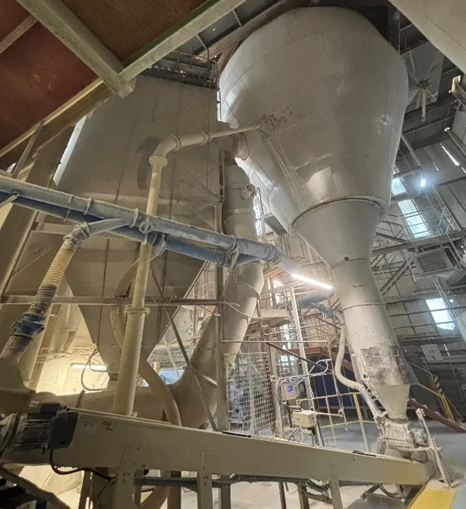
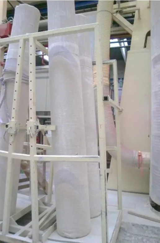
The raw material base for isostatic manufacturing is the same as for the traditional plastic process, i.e., kaolin, clays, alumina, and feldspar. However, particle size distribution and formulation are optimized for the spray drying process where the mixed slurry is dried to a fine, homogenous powder. Fig. 1 presents an example of a spray drying process scheme.
From the silos the powder is moved to the filling area where a rubber cannister inside a steel cylinder is filled. The filled cylinder is then transported by a carousel crane to the press (see Fig. 3).
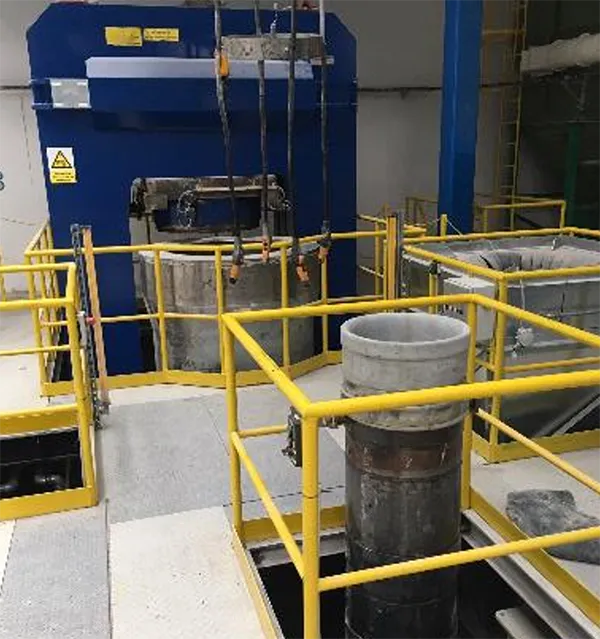
The pressure cycle takes several minutes and sees pressure increased up to 1050 bars. Afterwards, the body is a solid machinable ceramic cylinder, ready for turning.
After pressing, cylinders are moved directly to turning, glazing, and sanding operations before being loaded onto the kiln car for the firing cycle. From then on, manufacturing steps are identical with the conventional plastic process, i.e. visual inspection, cutting and grinding, assembly and final testing.
The isostatic manufacturing process results in a higher strength for the C-130 grade of porcelain body compared to conventional manufacturing and makes ceramic posts that are especially suitable for support insulators for demanding equipment applications.

Application of Room Temperature Vulcanized (RTV-1) Silicone
Spray coating is done in an industrial painting chamber with a strong suction system to eliminate free silicone particles from the air.
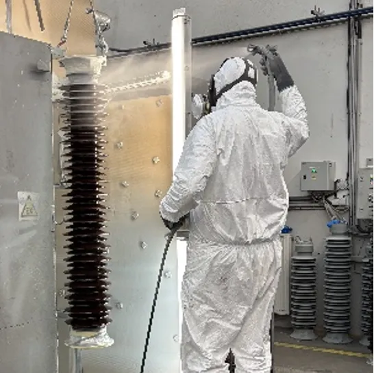
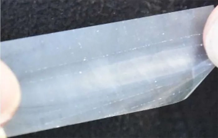
RTV coating is performed in 3 layers, with a curing period in between. The layers are approx. 125 µm to 150 µm in thickness (DFT – dry film thickness). Such a 3 step process results in good primary adhesion and homogenous thickness of the RTV coating. If necessary, a 4th layer can also be applied for specific design applications.

Qualification Process for Coated Post Insulators
Both mechanical and electrical type tests for each insulator are conducted according to IEC 60168 and as these are state-of-art. The focus here is therefore only on the qualification requirements for the RTV coating.
Homologation of RTV coated post insulators consists of type tests for RTV silicone characterization and tests on the applied RTV on the insulator.
1. Type Tests for Silicone Characterization
Type tests for silicone characterization are done on molded/cast silicone slabs while the tracking and erosion test is performed on ceramic tiles coated with RTV-1 material.
1. RTV Silicone Coating Thermogravimetric Analysis (TGA) – EN ISO 11358-1:2022
2. RTV Silicone coating differential scanning calorimetry (DSC) – EN ISO 11357-2:2022
3. RTV Silicone coating Fourier Transform Infrared Spectroscopy (FTIR) – EN 1767:1999
4. RTV Silicone coating density Measurements – ISO 2781:2018 Method A
5. RTV Silicone Tracking and erosion test – IEC 60587:2022
Tests 1 to 4 in this case were executed at an accredited external laboratory. The test report does not state if the results are a pass or a failure since these criteria are not defined. Rather, the report provides only the FTIR spectrum and a TGA-graph showing 3 material degradations between +300°C and +600°C with residual mass of about 40%. The DSC diagram shows that the RTV was thermally stable throughout the temperature range from -60°C to +200°C and that measured mass density is 1.383 g/cm3. The report does not give any interpretation of results.
Since it was difficult to find an accredited laboratory with proper equipment for the tracking and erosion test according to IEC 60587:2022, this was carried out at Trench Austria’s material laboratory using calibrated equipment. The factory at PPC Cab manufactured five C-130 ceramic plates measuring 120 mm x 50 mm x 6 mm, and these were coated with RTV-1 silicone material using the factory’s coating equipment.
Test parameters were as follows:
• Test voltage AC 4,5 kV
• Test frequency 50 Hz
• Series Resistance 33 kOhm
• Flow rate 0.6 ml/min
• Contaminant 2.53 S/m
• Test duration 6 hours
All samples passed, with maximum measured erosion depth of 0.65 mm and with no samples punctured or ignited.
Greater material wear of the RTV coating towards the lower electrode is typical behavior during this test.

2. Type Tests for Coated Insulators
The following tests were conducted as Factory Acceptance Test (FAT) for the finished coated insulators.
1. Visual examination after RTV coating – Customer Specification;
2. Silicone coating thickness measurement – Customer Specification;
3. Silicone coating adhesion test – EN ISO 2409;
4. Silicone coating hydrophobicity test – IEC TS 62073;
5. RTV silicone coating homogeneity test – Customer Specification.
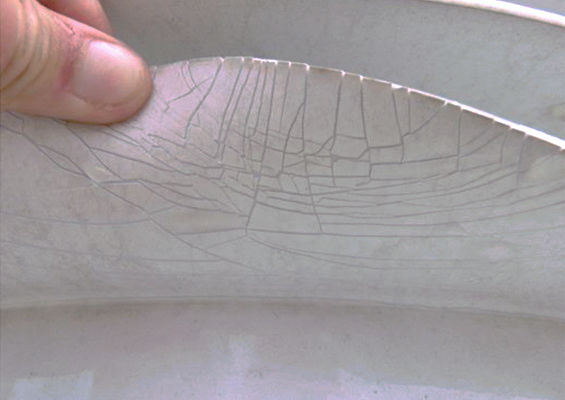
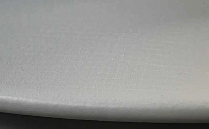
3. Visual Examination
The project specification called for: “The coating material must have a uniform surface both in appearance and color. There must be no diffuse drops, excessive roughness, or accumulation of material.” Three samples were examined, and all insulators selected passed.
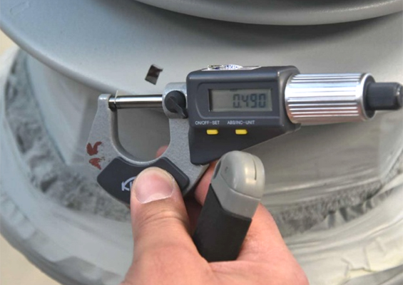
4. Silicone Coating Thickness Measurement (DFT)
Small rectangular samples of coating were taken as follows: top shed, middle shed, and bottom shed. At each location, a sample was taken from both sides of the shed, i.e. top and from below. Samples were then measured using a handheld micrometer caliper.
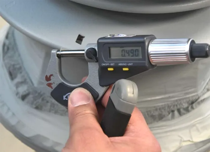
RTV dry-film coating thickness was specified as 400 µm on the upper side of the shed and 320 µm underneath. Measured values were:
Upper Shed – ave. 547 µm, min. 447 µm
Underneath – ave. 421 µm, min. 360 µm

5. Silicone Coating Adhesion Test
An RTV-coating adhesion test was performed according to clause 5.2.3.2 of ISO 2409, using a multiblade tool. With this tool, a cross-cut is created, and the area covered with self-adhesive tape. After removing the tape, the cross-cut surface is inspected to check for any coating particles that may have been removed.
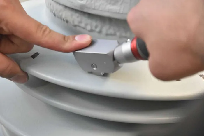
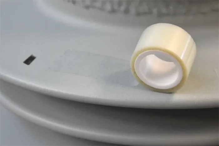
The result on all such adhesions tests was class 0, as specified in ISO 2049:

6. Coating Hydrophobicity Test
Hydrophobicity evaluation was conducted according to IEC TS 62073.
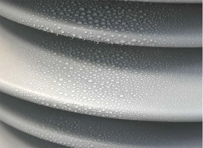
A hydrophobicity class of HC1 (as per IEC TS 62073) was observed on all samples tested.
7. Coating Homogeneity Test
The customer specification required that homogeneity of coating thickness be measured from 6 samples around one shed, 60° apart from each other and from 3 samples in line, starting one cm from shed tip to core, equally spaced. Variation in coating thickness is not permitted to be higher than ±20 % from the mean value. Homogeneity measurements were:
Around shed (6 x 60° apart) – mean 455 µm ±11%
Line (shed tip to core) – mean 466 µm ±1%.
The RTV coating homogeneity test was passed.
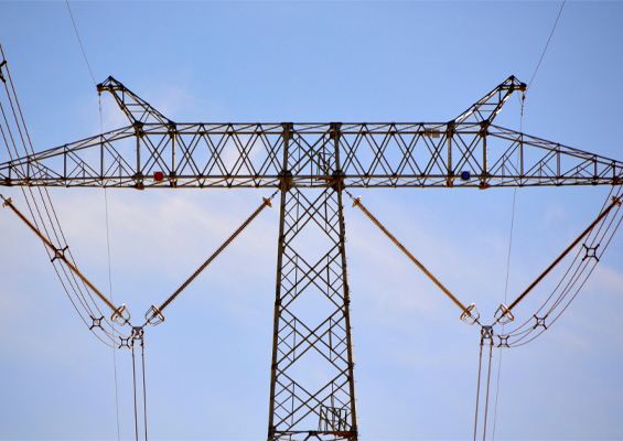
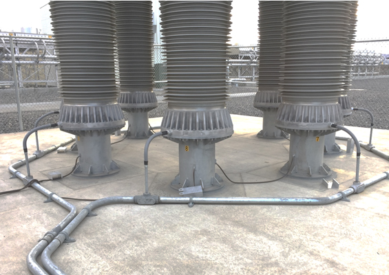
Post Insulator Application as HVDC Air-Core Dry-Type Reactor Support
In modern VSC (voltage sourced) HVDC schemes, air-core dry-type reactors are placed in the converter arms of the rectifiers and are needed for:
• di/dt limitation for the converter modules during switching;
• Short circuit protection for the converter modules;
• Limiting the rate-of-rise of short circuit currents;
• Improving the controllability of the converter to balance the current between the converter arms;
• Providing sufficient reactance between the VSC converter and the AC network to allow a good controllability of the power and reactive power exchanges between the AC network and the converter.
The reactors must be mechanically supported and electrically insulated from ground and other structures. This is the function of the ceramic post insulators.
Insulation to ground of these reactors is typically provided by ceramic post insulators. Depending on configuration of the HVDC scheme, these insulators are stressed by AC voltage, DC voltage or both, which imposes special requirements with regards to creepage distance and shed profile. In certain cases, additional insulation enhancement using RTV silicone coatings is specified.
These reactors are heavy, often tens of tons, and need to be designed for significant mechanical forces such as:
• static dead load;
• dynamic electromagnetic forces between the reactors during faults or high current surges;
• dynamic seismic loads;
• dynamic wind load (if outdoor);
• terminal loads; and
• combinations of the above.
Typically, HVDC applications demand extra-long creepage distance and insulator length due to limited creepage factors for DC application. In such applications, an additional HTM RTV-1 coating can be used to optimize design parameters of the ceramic post insulators.
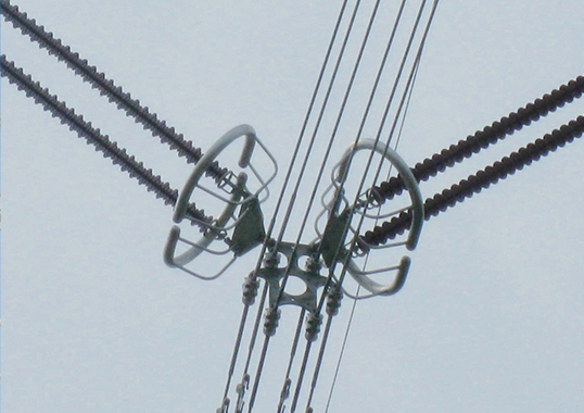
In practice, each single phase HVDC air-core reactor is mounted on tall post insulators arranged symmetrically around its base. The reactor (and if needed the insulators) are fitted with corona/grading rings to control electric field stresses. Use of ceramic post insulators for HVDC air-core dry-type reactor applications is well proven and application of RTV coatings in their design supports this application under severe environmental conditions.
Discussion & Conclusions
Initial silicone characterization tests, i.e. TGA, DSC, FTIR and silicone coating density (also known as ‘fingerprint testing’), were part of customer specification. The test report would basically state: ‘Yes’, the coating behaves like RTV according to these tests. An external laboratory stating that the FTIR spectra supports identification of the sample as a cured RTV silicone material does not really bring added value to a project. In fact, such requirements originated in a past era when RTV coatings were still a relatively new technology and any coating without clear traceability could have been proposed.
Today, by contrast, given that RTV coatings are state-of-the-art technology with known qualified and ISO-certified suppliers offering traceability and long-term experience, such fingerprint tests may no longer be necessary. At the same time, it should be noted that reproducibility of TGA, DSC and FTIR test results is not always evident, and their interpretation requires expertise which can sometimes create confusion. Following this logic, Working Group IEC TC/36 PT 63432 is proposing that these tests be moved to “for information only”.
In the case of this Project, homologation of the RTV coated post insulators was based on customer specifications and joint agreements. There was also some discussion of interpretation with regards to the correct test parameters. This type of situation can only improve now that IEC TS 63432 is clarifying the homologation process as well as the type tests required for all factory-coated glass or ceramic insulators.
The ceramic post insulators for this Project were factory-coated before delivery to the customer. This was done under controlled conditions that allowed excellent adhesion and homogenous coating thickness to guarantee long service life. This is a significant advantage compared to on-site coating whereby insulators need to be cleaned and protected against dust and rain during the coating process. Such critical conditions can risk variation in coating thickness. Moreover, de-energization of a line or substation for field coating makes this process far more costly.
Factory-coated insulators require adapted packaging to avoid damage during transport as well as special care during installation. Sill, any minor damage can be touched up afterwards. Repair is simple and can also be used whenever an RTV coating needs to be restored after dry-film thickness measurements, control of thickness homogeneity and adhesion tests.
Technical Specification, IEC TS 63432, will only accelerate the trend of using RTV-coated ceramic insulators for HVDC applications which require rigidity, compression strength and good pollution performance.

Bibliography
1. IEC CD 63432: “RTV silicone rubber coated insulators for AC and DC high-voltage applications – definitions, test methods and acceptance criteria”, Date of circulation 2025-07-11
2. IEC 60168:1994 Ed. 4.0 “Tests on indoor and outdoor post insulators of ceramic material or
3. glass for systems with nominal voltages greater than 1000 V”
4. EN ISO 11358-1:2022 Ed. 2.0 “ Plastics – Thermogravimetry (TG) of polymers – Part 1: General principles”
5. EN ISO 11357-2:2022 Ed. 3.0 “Plastics – Differential scanning calorimetry (DSC) – Part 2: Determination of glass transition temperature and step height”
6. EN 1767:1999 “Products and systems for the protection and repair of concrete structures – Test methods – Infrared analysis”
7. ISO 2781:2018 Ed. 5.0 “Rubber, vulcanized or thermoplastic – Determination of density”
8. IEC 60587:2022, ed. 4.0 ”Electrical insulating materials used under severe ambient conditions – Test methods for evaluating resistance to tracking and erosion”
9. EN ISO 2409:2020 Ed. 5.0 “Paints and varnishes – Cross-cut test”
10. IEC TS 62073:2016 Ed. 2.0 “Guidance on the measurement of hydrophobicity of insulator surfaces”